0 Contents - Hilti Svenska AB
0 Contents - Hilti Svenska AB
0 Contents - Hilti Svenska AB

Create successful ePaper yourself
Turn your PDF publications into a flip-book with our unique Google optimized e-Paper software.
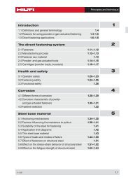
<strong>Contents</strong><br />
Product index DX / GX fasteners 4.1–4.238<br />
Alphabetical list of fastener 4.2–4.3<br />
Fastener program 4.5–4.221<br />
Tools and equipment 4.223–4.238<br />
11 / 2007 4.1
Product Index DX/GX Fastener<br />
Product Index for DX / GX Fastener<br />
Designation Description Page<br />
X-AL-H General Purpose Nails 4.95<br />
X-BT Stainless Steel Threaded Studs 4.47<br />
X-CR Stainless Steel Nails for Concrete, Sand lime<br />
Masonry and Steel 4.115<br />
X-CR Special Stainless Steel Nails for Fastening to Steel 4.217<br />
X-CRM Stainless Steel Threaded Studs for Concrete<br />
and Steel 4.157<br />
X-DNI General Purpose Nails for Concrete,<br />
Sandlime-Masonry and Steel 4.101<br />
DS Heavy Duty General Purpose Nails<br />
for Concrete and Steel 4.135<br />
X-DW, X-ZF, X-DAK, ESD DX Drywall Fasteners 4.123<br />
X-ECT MX Electrical Cable Tie, X-EKS MX and X-EMTSC<br />
Conduit Clip Fastener 4.205<br />
X-EDNI, EDS General Purpose Nails for Steel 4.41<br />
X-EDNK22 THQ12,<br />
X-EDN19 THQ12 Diaphragm Decking Nails 4.35<br />
X-EGN, X-GPH, X-GN GX Drywall Fasteners 4.129<br />
X-EKB, X-ECH Electrical Cable Fasteners 4.189<br />
X-EM6H, X-EW6H, X-EF7H,<br />
X-EM8H, X-EM10H, X-EW10H Threaded Studs for Steel 4.53<br />
X-ENP Siding and Decking Nail 4.5<br />
X-ENP2K Siding and Decking Nail 4.13<br />
X-ET For Fastening Plastic Electrical Cable Trays<br />
and Junction Boxes 4.211<br />
X-FB (X-BX / X-EMTC) Electrical Conduit Fasteners 4.197<br />
X-FCM Grating Fastening System 4.59<br />
X-FCP Checker Plate Fastening System 4.79<br />
X-FS Form Stop 4.173<br />
X-GR Grating Fastening System 4.67<br />
X-GRRU Grating Fastening System 4.71<br />
X-HS Threaded Hanger and X-CC Loop Hanger Systems 4.177<br />
X-HSMX and X-CCMX Electrical Hanger Systems 4.183<br />
X-HVB Shear Connectors 4.27<br />
4.2 11 / 2007
Product Index DX/GX Fastener<br />
Designation Description Page<br />
X-IE Wall Insulation Fastener 4.165<br />
DX-Kwik X-M6H, X-M8H Threaded Studs and DNH, X-DKH Nails 4.151<br />
X-MGR Grating Fastening System 4.75<br />
X-M6, X-W6, X-F7,<br />
X-M8, X-M10, X-W10 Threaded Studs for Concrete 4.145<br />
NPH Siding and Decking Nails to Concrete 4.21<br />
SDK2 Sealing Caps for Cladding Fastening 4.19<br />
SL Nails for Forming or other Temporary uses 4.141<br />
X-SW30, X-SW60 Soft Washer Fastener 4.169<br />
X-U General Purpose Nails for Concrete and Steel 4.85<br />
X-ZF General Purpose Nails for Concrete,<br />
Sand lime-Masonry and Steel 4.109<br />
11 / 2007 4.3
4.4 11 / 2007
X-ENP Siding and Decking Nail<br />
Product data<br />
Dimensions<br />
o 4.5<br />
yellow<br />
Applications<br />
Examples<br />
o 7.4<br />
o 15<br />
23.8<br />
General information<br />
Material specification<br />
Carbon steel shank: HRC 58<br />
Zinc coating: 8–16 µm<br />
Fastening tools<br />
Single nail:<br />
DX 76 F15 X-ENP-19 L15<br />
Collated nails:<br />
DX 76 PTR, DX 76 MX X-ENP-19 L15 MX,<br />
white magazine strip<br />
DX 860-ENP X-ENP-19 L15 MXR,<br />
grey magazine strip<br />
See fastener selection for more details.<br />
Approvals<br />
ETA-04/0101 (Europe),<br />
UL R13203, FM 3021719 (USA), MLIT (Japan)<br />
Roof decking Floor decking Wall liners<br />
X-ENP<br />
The intended use only comprises fastenings which are not directly exposed to external<br />
weather conditions or moist atmospheres. For out-door applications that can be ensured by<br />
using SDK 2 sealing caps, see corresponding chapter of this manual. Fastening of Aluminum<br />
sheeting is generally recommended only for indoor conditions.<br />
11 / 2007 4.5
X-ENP<br />
Load data<br />
Characteristic loads – Steel sheeting<br />
Sheeting Trapezoidal profile Liner trays 1)<br />
Design data<br />
thickness (symmetric loading) (asymmetric loading)<br />
tI [mm] Char. resistance Char. resistance<br />
according to ETA-04/0101 keeping to ETA-04/0101<br />
Shear Tension Shear Tension<br />
nominal VRk [kN] NRk [kN] VRk [kN] NRk [kN]<br />
0.63 4.00 4.10 2.80 2.90<br />
0.75 4.70 6.30 3.30 4.40<br />
0.88 5.40 7.20 3.80 5.00<br />
1.00 6.00 8.00 4.20 5.60<br />
1.13 7.00 8.40 4.90 5.90<br />
1.25 8.00 8.80 5.60 6.20<br />
1.50 8.60 8.80 6.00 6.20<br />
1.75 8.60 8.80 6.00 6.20<br />
2.00 8.60 8.80 6.00 6.20<br />
2.50 8.60 8.80 6.00 6.20<br />
• NRk and VRk are valid for steel sheet with minimum tensile strength ≥ 360 N/mm 2 (≥ S280 EN 10326).<br />
• For intermediate sheet thicknesses, use recommended load for next smaller thickness or linear interpolation.<br />
1) Required load reduction is taken into account in accordance with Eurocode 3-1-3, section 8.4 (9) and fig. 8.2.<br />
See also construction rules under spacings and edge distances.<br />
Recommended loads – Steel sheeting<br />
Sheeting Trapezoidal profile Liner trays 1)<br />
thickness (symmetric loading) (asymmetric loading)<br />
tI [mm] Recommended loads Recommended loads<br />
Shear Tension Shear Tension<br />
nominal Vrec [kN] Nrec [kN] Vrec [kN] Nrec [kN]<br />
0.63 2.10 2.20 1.50 1.55<br />
0.75 2.50 3.35 1.75 2.35<br />
0.88 2.90 3.85 2.00 2,70<br />
1.00 3.20 4.25 2.25 3.00<br />
1.13 3.75 4.50 2.65 3.15<br />
1.25 4.25 4.70 3.00 3.30<br />
1.50 4.60 4.70 3.20 3.30<br />
1.75 4.60 4.70 3.20 3.30<br />
2.00 4.60 4.70 3.20 3.30<br />
2.50 4.60 4.70 3.20 3.30<br />
• Nrec and Vrec are valid for steel sheet with minimum tensile strength ≥ 360 N/mm 2 (≥ S280 EN 10326).<br />
• For intermediate sheet thicknesses, use recommended load for next smaller thickness or linear interpolation.<br />
• Recommended loads Nrec and Vrec are appropriate for Eurocode 1 wind loading design with a partial safety<br />
factor γF =1.5 for wind load and a partial resistance factor γM = 1.25 for the fastening.<br />
1) Required load reduction is taken into account in accordance with Eurocode 3-1-3, section 8.4 (9) and fig. 8.2.<br />
See also construction rules under spacings and edge distances.<br />
4.6 11 / 2007
Recommended loads – Aluminum sheeting 1) with fu ≥ 210 N/mm 2<br />
Trapezoidal profile (symmetric loading)<br />
Thickness Shear Tension<br />
tI [mm] Vrec [kN] Nrec [kN]<br />
0.60 0.75 0.35<br />
0.70 0.90 0.50<br />
0.80 1.00 0.65<br />
0.90 1.20 0.80<br />
1.00 1.30 0.95<br />
1.20 1.55 1.30<br />
1.50 1.85 1.45<br />
X-ENP<br />
2.00 2.55 1.90<br />
1) Constraint forces and corrosion aspects have to be considered.<br />
• For intermediate sheet thicknesses, use recommended load for next smaller thickness.<br />
• Recommended loads Nrec and Vrec are appropriate for Eurocode 1 wind loading design with a partial safety<br />
factor of γF =1.5 for wind load and a partial resistance factor γM = 1.25 for the fastening.<br />
Recommended loads – Other applications<br />
Vrec [kN] Nrec [kN]<br />
4.0 2.4<br />
• Fastened Parts: Clips, brackets, etc.; thick steel parts.<br />
• Redundancy (multiple fastening) must be provided.<br />
• The possibility of prying effects has to be considered<br />
• Failure of the fastened part is not considered in these values of Nrec, Vrec.<br />
• Valid for predominantly static loading<br />
• Global factor of safety is ≥ 3 based on 5% fractile value<br />
≥ 5 based on mean value<br />
Design<br />
Depending on the verification concept, the corresponding design criteria are given as following.<br />
Working load concept Partial safety concept<br />
Tensile loads N Sk ≤ N rec N Sd ≤ N Rd<br />
Shear loads V Sk ≤ V rec V Sd ≤ V Rd<br />
N-V Interaction<br />
For combined tensile and shear forces on the fastener, a linear function has to be used.<br />
( ) +( ) ≤ 1 ( ) +(<br />
VSk NSk VSd NSd) V rec<br />
N rec<br />
with: with:<br />
VSk, NSk unfactored characteristic load acting VSd, NSd Design load with γF = 1.5<br />
on the fastening (= working load) VRd, NRd Design resistance of the fastening<br />
Vrec, Nrec recommended (allowable) load with with γM = 1.25<br />
γGLOB = 1.875 VRd = VRk / 1.25<br />
NRd = αcycl NRk / 1.25<br />
αcycl = 1.0 according to ETA-04/0101<br />
11 / 2007 4.7<br />
V Rd<br />
N Rd<br />
≤ 1
X-ENP<br />
Test Data<br />
Testing and evaluation of design data have been done in accordance to European Technical<br />
Approval ETA-04/0101 which refers to Eurocode 3, part 1–3 (ENV 1993-1-3). The test procedure<br />
is described in detail in section Direct Fastening Technology of this manual.<br />
Application Requirements<br />
Thickness of base material<br />
Steel thickness tII<br />
tII<br />
Thickness of fastened material<br />
Sheet thicknesses and overlap types<br />
(a)<br />
single<br />
tII ≥ 6 mm<br />
(b)<br />
side lap<br />
(c)<br />
end overlap<br />
Nominal sheeting thickness tI [mm] Allowable overlap types<br />
0.63–1.00 a, b, c, d<br />
> 1.00–1.25 a, c<br />
(d)<br />
side lap and end overlap<br />
> 1.25–2.50 a<br />
With the above recommended sheet thickness and overlap types, it is not necessary to take<br />
into account the effect of constraints due to temperature for steel grades up to S320 (EN<br />
10326). For steel grade S350 (EN 10326) it shall be considered for design. Sheets of grade<br />
S350 on base material tII ≥ 8 mm have been verified by <strong>Hilti</strong>, forces of constraint can be neglected.<br />
4.8 11 / 2007
Spacing and edge distances (mm)<br />
Steel base material<br />
15<br />
Trapezoidal profiles<br />
Center fastenings in<br />
ribs<br />
Liner trays<br />
90°<br />
c<br />
Clearance to side of<br />
sheet<br />
7<br />
20<br />
Clearance to end of<br />
sheet<br />
c<br />
75<br />
c<br />
(1)<br />
Clearance to side of<br />
sheet<br />
c ≤ 75 mm if possible<br />
1) If not possible, then as close as possible with fastening<br />
90° to surface plus a second fastener at the other<br />
side of the tray (as shown in graphs above).<br />
X-ENP<br />
Corrosion information<br />
The intended use only comprises fastenings which are not directly exposed to external<br />
weather conditions or moist atmospheres. For out-door applications that can be ensured by<br />
using SDK 2 sealing caps, see corresponding chapter of this manual. Fastening of Aluminum<br />
sheeting is generally recommended only for indoor conditions. For further detailed information<br />
on corrosion see corresponding chapter in section Direct Fastening Technology.<br />
11 / 2007 4.9<br />
20<br />
10<br />
7<br />
45<br />
Double fastenings (asymmetric)<br />
Note:<br />
Reduced recommended load per fastening.<br />
Reduction depends on actual spacing and conditions.<br />
For further information contact <strong>Hilti</strong>.<br />
20<br />
Clearance to end of<br />
sheet<br />
80<br />
Fastener spacing along<br />
sheet
X-ENP<br />
Recommended setting range<br />
X-ENP-19 with DX 76 and DX 860-ENP X-ENP-19 with DX 76 PTR<br />
Steel thickness tII [mm]<br />
22<br />
21<br />
20<br />
10<br />
18<br />
17<br />
16<br />
15<br />
14<br />
13<br />
12<br />
11<br />
10<br />
9<br />
8<br />
7<br />
Applicable<br />
range of base<br />
materials<br />
S 235 Jxx<br />
S 275 Jxx<br />
S 355 Jxx<br />
6 350 400 450 500 550 600 650 700 750<br />
Steel strength Rm [N/mm2 ]<br />
6 350 400 450 500 550 600 650 700 750<br />
4.10 11 / 2007<br />
Steel thickness tII [mm]<br />
22<br />
21<br />
20<br />
10<br />
18<br />
17<br />
16<br />
15<br />
14<br />
13<br />
12<br />
11<br />
10<br />
9<br />
8<br />
7<br />
Applicable<br />
range of base<br />
materials<br />
S 235 Jxx<br />
S 275 Jxx<br />
S 355 Jxx<br />
Steel strength Rm [N/mm 2]<br />
Working beyond the recommended application range will lead to an increase of the failure<br />
rate.<br />
Fastener selection and system recommendation<br />
Fasteners Tools<br />
Designation Item-Number<br />
Single nail: X-ENP-19 L15 283506 DX 76 F15, DX 76 PTR<br />
Collated nails: X-ENP-19 L15 MX, 283507 DX 76 MX, DX 76 PTR<br />
white cartridge strip<br />
X-ENP-19 L15 MXR, 283508 DX 860-ENP<br />
grey cartridge strip
Cartridge selection and tool energy setting<br />
DX 76 and DX 860-ENP<br />
>20<br />
10<br />
Red 4<br />
DX 76 PTR<br />
18<br />
17<br />
16<br />
15<br />
14<br />
or<br />
Black 2<br />
Black 4<br />
13<br />
Red 3<br />
or<br />
Black 3<br />
12<br />
11<br />
10<br />
Black 1<br />
9<br />
Blue 4 or<br />
Red 4 or<br />
8<br />
Red 2<br />
Black 2<br />
7<br />
Blue 3 Red 3<br />
6<br />
S 235 S 355<br />
Steel thickness t II [mm]<br />
X-ENP<br />
Fine adjustment by installation tests on site.<br />
Note for S275:<br />
Start with recommendation for S355. In case of too much energy: Reduction of tool energy<br />
setting or change of cartridge color till correct nail head stand-offs hNVS are achieved<br />
11 / 2007 4.11
X-ENP<br />
Fastening quality assurance<br />
Fastening inspection<br />
h NVS<br />
t II<br />
Σt I,tot ≤ 4 mm<br />
hNVS = 8.2–9.8 mm for tI,tot ≤ 4 mm<br />
Max<br />
Min<br />
X-ENP-19 L15<br />
Max<br />
Min<br />
X-ENP-19 L15<br />
hNVS = 8.2–9.8 mm hNVS > 8.2–9.8 mm<br />
(washers are not compressed)<br />
X-ENP-19 L15<br />
4.12 11 / 2007<br />
Max<br />
Min<br />
hNVS < 8.2–9.8 mm<br />
(washers are strongly damages by<br />
the tool piston)
X-ENP 2K Siding and Decking Nail<br />
Product data<br />
Dimensions<br />
o 3.7<br />
o 7.4<br />
o 15<br />
Applications<br />
Examples<br />
25.5<br />
General information<br />
Material specification<br />
Carbon steel shank: HRC 55.5<br />
Zinc coating: 8–16 µm<br />
Fastening tools<br />
Single nail:<br />
DX 76 F15, DX 76 PTR: X-ENP 2K-20 L15<br />
Collated nails:<br />
DX 76 MX, DX 76 MX PTR: X-ENP 2K-20 L15 MX<br />
(green magazine strip)<br />
See fastener selection for more details.<br />
X-ENP 2K<br />
Approvals<br />
CSTB (France),<br />
BUtgb (Belgium)<br />
Note: Technical data presented in these approvals and<br />
design guidelines reflect specific local conditions and may<br />
differ from those published in this handbook.<br />
Roof and floor decking Roof and floor decking Wall liners<br />
11 / 2007 4.13
X-ENP 2K<br />
Load data<br />
Design data<br />
Recommended loads<br />
Sheeting thickness Trapezoidal profile Liner trays<br />
tI [mm] (symmetric (asymmetric)<br />
nominal minimum Nrec [kN] Vrec [kN] Nrec [kN] Vrrec [kN]<br />
0.63 –– 1.20 1.40 –– ––<br />
0.75 0.65 1.80 1.70 1.25 1.20<br />
0.88 0.77 2.10 2.00 1.50 1.40<br />
1.00 0.89 2.70 2.20 1.90 1.55<br />
1.13 1.02 3.00 2.60 2.10 1.80<br />
1.25 1.13 3.00 3.00 2.10 2.10<br />
1.50 1.36 3.00 3.00 2.10 2.10<br />
1.75 1.60 3.00 3.00 2.10 2.10<br />
2.00 1.84 3.00 3.00 2.10 2.10<br />
• Recommended working loads valid for steel sheet minimum tensile strength ≥ 360 N/mm 2 .<br />
• For intermediate sheet thicknesses, use recommended load for next smaller thickness.<br />
• Recommended loads include safety factor e 3.0 applied to characteristic loads NRk and VRk and are appropriate<br />
for EC 1 (or similar) wind loading designs.<br />
• For steel thickness, tII = 3–4 mm, reduce all recommended loads to 0.9 kN.<br />
Test data (examples)<br />
Important note: Test data are for information only and can't be used for design. These data<br />
are examples and not representing the whole range of applications and load cases. Recommended<br />
loads are in conjunction with allowable sheet thicknesses and overlap types. For<br />
more detailed information please contact <strong>Hilti</strong>.<br />
Characteristic tensile load Characteristic shear load<br />
Pull-out (base material) Pull-over (sheeting) Base steel Sheeting<br />
tII [mm] Ntest, k 1) [kN] tI [mm] Ntest, k [kN] tII [mm] tI [mm] Vtest, k [kN]<br />
2.7 6.52 0.75 6.70 5.0 0.75 5.91<br />
3.0 6.84 1.00 7.84 5.0 1.00 7.79<br />
6.0 6.88 1.25 10.24 5.0 1.25 10.09<br />
1) with 1 x 0.75 mm sheeting<br />
Application requirements<br />
Thickness of base material<br />
tII = 4 -8mm<br />
tII = 4.0–8.0 mm for general shapes tII = 2.7–3.3 mm for concrete inlays<br />
4.14 11 / 2007<br />
tII = 2.7 -3.3mm
Thickness of fastened material<br />
Sheet thicknesses and overlap types<br />
(a)<br />
single<br />
(b)<br />
side lap<br />
(c)<br />
end overlap<br />
Nominal sheeting thickness Overlap types<br />
tI [mm] tII = 3–4 mm tII ≥ 4 mm<br />
0.63–0.75 a, b, c, d a, b, c, d<br />
X-ENP 2K<br />
(d)<br />
side lap and end overlap<br />
> 0.75–1.00 a, c a, b, c, d<br />
• The recommendations apply if the supporting structure is flexible enough so that forces of constraint from<br />
temperature differentials can be neglected.<br />
• These recommendations are valid for sheets up to S350GD.<br />
Spacing and edge distances (mm)<br />
Rolled I or wide flange shapes Angels<br />
tII = 4-8<br />
10<br />
11 / 2007 4.15<br />
bx**<br />
tII = 4 - 8*<br />
* For tII = 3 to 4 mm, restrictions on application. See approval or contact <strong>Hilti</strong>.<br />
** Maximum recommended bx ≤ 8 x tII however, jobsite verification advisable.<br />
Trapezoidal profiles<br />
Center fastenings in<br />
ribs<br />
20<br />
Clearance to end of<br />
sheet<br />
20<br />
10<br />
45<br />
Double fastenings<br />
Note:<br />
Reduced recommended load per fastening.<br />
Reduction depends on actual spacing and conditions.<br />
For further information contact <strong>Hilti</strong>.
X-ENP 2K<br />
Liner trays<br />
90°<br />
c<br />
Clearance to side of<br />
sheet<br />
c<br />
75<br />
c<br />
Clearance to side of<br />
sheet<br />
c ″ 75 mm if possible<br />
1) If not possible, then as close as possible with fastening<br />
90° to surface plus a second fastener at the other<br />
side of the tray (as shown in graphs above).<br />
Corrosion information<br />
The intended use only comprises fastenings which are not directly exposed to external<br />
weather conditions or moist atmospheres. For out-door applications that can be ensured by<br />
using SDK 2 sealing caps. For further detailed information on corrosion see corresponding<br />
chapter in section Direct Fastening Technology.<br />
Recommended setting range<br />
Steel thickness, tII [mm]<br />
9<br />
8<br />
7<br />
6<br />
5<br />
4<br />
S 235<br />
S 275<br />
2.7<br />
S 355<br />
350 400 450 500 550 600 650<br />
Steel strength Rm [N/mm2 ]<br />
Fastener selection and system recommendation<br />
4.16 11 / 2007<br />
20<br />
Clearance to end of<br />
sheet<br />
80<br />
Fastener spacing along<br />
sheet<br />
Working beyond the recommended application<br />
range will lead to an increase of the failure<br />
rate.<br />
Fasteners Tools<br />
Designation Item-Number<br />
Single nail: X-ENP 2K-20 L15 385133 DX 76 F15, DX 76 PTR<br />
Collated nails: X-ENP 2K-20 L15 MX 385134 DX 76 MX, DX 76 PTR
Cartridge selection and tool energy setting<br />
DX 76 DX 76 PTR<br />
Steel thickness, tII [mm]<br />
8<br />
6<br />
5<br />
4<br />
2.7-3.3<br />
Blue 3<br />
Blue 2<br />
Yellow 4<br />
Green 4<br />
Green 1<br />
Cartridge selection<br />
Fine adjustment by installation tests on site.<br />
Fastening quality assurance<br />
Fastening inspection<br />
Max<br />
Min<br />
hNVS<br />
X-ENP2K-20 L15<br />
Max<br />
Min<br />
X-ENP 2K<br />
11 / 2007 4.17<br />
Steel thickness, tII [mm]<br />
6<br />
5<br />
4<br />
2.7-3.3<br />
X-ENP2K-20 L15<br />
hNVS = 7–11 mm hNVS > 7–11 mm<br />
(washers are not compressed)<br />
Max<br />
Min<br />
Blue 4<br />
Green 4<br />
Cartridge selection<br />
hNVS = 7–11 mm<br />
hNVS = 8.2–9.8 mm when used in combination with SDK2 sealing cap<br />
(see page fastener inspection for X-ENP)<br />
X-ENP2K-20 L15<br />
hNVS < 7–11 mm<br />
(washers are strongly damages by<br />
the tool piston)
X-ENP 2K<br />
4.18 11 / 2007
SDK2 Sealing Caps for Cladding Fastening<br />
Product data<br />
Dimensions<br />
SDK 2 sealing cap<br />
stainless steel<br />
(DIN 1.4301)<br />
ASTM 304)<br />
neoprene<br />
Applications<br />
Examples<br />
A<br />
A<br />
22.5<br />
A A<br />
Roof and wall cladding on single<br />
skin buildings<br />
14.7<br />
SDK 2<br />
General information<br />
Compatible DX fasteners<br />
X-ENP-19 L15 Base material thickness tII ≥ 6 mm<br />
X-ENP 2K-20 L15 Base material thickness tII = 3–6 mm<br />
Fastening tool<br />
SW/SDK2 setting tool<br />
Stainless steel cap not affected by<br />
atmospheric corrosion<br />
Space under the cap isolated from<br />
the atmosphere<br />
Neoprene washer insulates against<br />
contact corrosion and seals the space<br />
under the cap-off from the atmosphere<br />
Pressure the washer seals the gap<br />
between the sheet and the base steel<br />
Corrosion protection<br />
11 / 2007 4.19
SDK 2<br />
Fastening quality assurance<br />
Fastening inspection<br />
For detailed information on X-ENP-19 L15 and ENP2K-20 L15 please see the according<br />
product pages.<br />
X-ENP-19 L15<br />
hNVS = 8.2–9.8 mm<br />
Installation<br />
90°<br />
≤10°<br />
hNVS<br />
X-ENP 2K-20 L15<br />
≤10°<br />
Position the DX tool so that nail inclination is limited to<br />
max. 10° from perpendicular to surface<br />
90° ≥ 38 mm<br />
4.20 11 / 2007<br />
hNVS<br />
Centre fastening in valley.<br />
38 mm min. valley width<br />
≥ 6°<br />
Minimum roof slope 6°
NPH Siding and Decking Nails to Concrete<br />
Product data<br />
Dimensions<br />
o 4.5<br />
o 7.4<br />
o 15<br />
Applications<br />
Examples<br />
46.8<br />
General information<br />
Material specification<br />
Carbon steel shank: HRC 58<br />
Zinc coating: 8–16 µm<br />
Fastening tools<br />
Cartridges:<br />
DX 76 F15, DX 750: 6.8/18M blue<br />
See fastener selection for more details.<br />
Approvals<br />
SOCOTEC (France)<br />
BUtgb (Belgium)<br />
Roof decking Wall liners<br />
City of Vienna<br />
Note: Technical data presented in these approvals and<br />
design guidelines reflect specific local conditions and may<br />
differ from those published in this handbook.<br />
11 / 2007 4.21<br />
NPH
NPH<br />
Load data<br />
Design data<br />
Recommended loads<br />
Sheeting thickness Trapezoidal profile Liner trays<br />
tI [mm] (symmetric (asymmetric)<br />
nominal minimum Nrec [kN] Vrec [kN] Nrec [kN] Vrec [kN]<br />
0.75 0.65 1.80 1.20 1.30 1.20<br />
0.88 0.77 2.10 1.50 1.50 1.50<br />
1.00 0.89 2.40 1.80 1.70 1.80<br />
1.13 1.02 2.70 2.20 1.90 2.20<br />
1.25 1.13 3.00 2.50 2.10 2.50<br />
1.50 1.36 3.00 3.00 2.50 3.00<br />
1.75 1.60 3.00 3.00 2.50 3.00<br />
2.00 1.84 3.00 3.00 2.50 3.00<br />
• Recommended working loads valid for steel sheets with a minimum tensile strength of ≥ 360 N/mm 2 .<br />
• For intermediate sheet thicknesses, use recommended load for next smaller thickness.<br />
• Recommended loads are appropriate for EC1 (or similar) wind loading designs.<br />
• The safety factor included is at least 2.0 applied to the static 5 % fractile value and 1.3 to the cyclic (5000<br />
cycles) 5 % fractile value<br />
Test data<br />
Important note: Test data are for information only and can't be used for design. These data<br />
are examples and not representing the whole range of applications and load cases. Recommended<br />
loads are in conjunction with allowable sheet thicknesses and overlap types. For<br />
more detailed information please contact <strong>Hilti</strong>.<br />
Characteristic tensile load Characteristic shear load<br />
Pull-out (concrete) Pull-over (sheeting) Concrete Sheeting<br />
fcc [MPa] Ntest,k [kN] tI [mm] Ntest,k [kN] fcc [MPa] tI [mm] Vu, m [kN]<br />
28.1 10.46 0.75 7.80 39.0 2 x 1.25 12.8<br />
63.2 9.50 1.00 8.99 56.0 2 x 1.25 13.4<br />
Application Requirements<br />
1.25 10.29<br />
Thickness of base material<br />
Minimum thickness of concrete member hmin = 160 mm<br />
4.22 11 / 2007
Thickness of fastened material<br />
Sheet thicknesses and overlap types<br />
(a)<br />
single<br />
(b)<br />
side lap<br />
(c)<br />
end overlap<br />
Nominal sheeting thickness tI [mm] Allowable overlap types<br />
0.63–1.13 a, b, c, d<br />
11 / 2007 4.23<br />
NPH<br />
(d)<br />
side lap and end overlap<br />
> 1.13–2.50 a<br />
• With the above recommended sheet thickness and overlap types, the effects of temperature induced forces of<br />
constraint during construction can be neglected.<br />
• These recommendations are valid for sheets up to S350GD.<br />
• With other sheets or overlaps or when unusually large forces of constraint are expected, analyze the structural<br />
system to insure that the shear force acting on the nail does not exceed Vrec.<br />
Spacing and edge distances (mm)<br />
Trapezoidal profiles to girders or purlins<br />
Liner trays to columns<br />
300<br />
300<br />
90<br />
180<br />
300<br />
100<br />
100<br />
90<br />
Corrosion information<br />
The intended use only comprises fastenings which are not directly exposed to external<br />
weather conditions or moist atmospheres. For further detailed information on corrosion see<br />
corresponding chapter in section Direct Fastening Technology.<br />
75<br />
200<br />
75<br />
20<br />
100<br />
200<br />
100<br />
20<br />
12<br />
150<br />
90∞
NPH<br />
Recommended setting range<br />
Types of concrete • Precast and cast-in-place pre-stressed concrete<br />
• Precast and cast-in-place reinforced concrete<br />
Concrete design strength • Minimum C20/25 (fcc = 20 N/mm 2 , fc = 25 N/mm 2 )<br />
• Maximum C45/55 (fcc = 45 N/mm 2 , fc = 55 N/mm 2<br />
• The NPH/DX-Kwik system has been successfully used in<br />
concrete having an in-place cube strength of 70 N/mm 2<br />
Minimum strength/age at • C20/25 concrete must be 28 days old<br />
time of fastening • C45/55 concrete must be 15 days old<br />
Minimum dimensions • Minimum width = 180 mm<br />
of concrete member • Minimum thickness = 160 mm<br />
Fastener selection<br />
Fasteners Tool<br />
Designation Item no.<br />
NPH2-42 L15 40711 DX 76 F15<br />
Cartridge selection and tool energy setting<br />
Cartridges 6.8/18 M blue<br />
Tool energy adjustment by setting tests on site<br />
Fastening quality assurance<br />
Fastening inspection<br />
23<br />
NPH2-42 L15<br />
7.5 -11 mm<br />
1. Insure that pre-drilling is<br />
done with the recommended<br />
bit TX-C-5/23 (Item-<br />
Number: 291934)<br />
2. Check for conformance to<br />
recommendations (detailing<br />
spacing and edge distances<br />
for fastening)<br />
3. Check the nail head standoff<br />
of completed fastenings<br />
4.24 11 / 2007
Installation<br />
Pre-drill with TX-C-5/23 drill bit<br />
(Item-Number: 291934)<br />
Place fastener with DX 76 / DX 750 Fastening completed<br />
11 / 2007 4.25<br />
NPH
NPH<br />
4.26 11 / 2007
X-HVB Shear Connectors<br />
Product data<br />
Dimensions<br />
X-HVB 140 X-HVB 125<br />
2.5<br />
51<br />
63<br />
142.5<br />
20.6<br />
31<br />
2.5<br />
X-HVB 110 X-HVB 95<br />
2<br />
51<br />
63<br />
112.5<br />
X-HVB 80<br />
2<br />
50<br />
60<br />
80<br />
20.6<br />
31<br />
24.3<br />
X-ENP-21 HVB<br />
(Former designation<br />
of the Nail was<br />
ENPH2-21L15)<br />
o 4.5<br />
yellow<br />
o 7.4<br />
o 15<br />
51<br />
63<br />
2<br />
50<br />
60<br />
127.5<br />
95<br />
X-HVB 50<br />
2<br />
50<br />
88<br />
25.8<br />
52<br />
20.6<br />
31<br />
24.3<br />
24.3<br />
General information<br />
Material specification<br />
X-HVB<br />
X-HVB<br />
Carbon steel: Rm = 295–350 N/mm 2<br />
Zinc coating: ≥ 3 µm<br />
X-ENP-21 HVB<br />
Carbon steel shank: HRC58<br />
Zinc coating: 8–16 µm<br />
Fastening tools and equipment<br />
Tool DX 76<br />
Fastener Guide X-76-F-HVB<br />
Piston X-76-P-HVB<br />
Cartridges 6.8/18M black, red<br />
(details see application<br />
limit X-ENP-21 HVB)<br />
See fastener selection for more details.<br />
Approvals and design guidelines<br />
SOCOTEC (France)<br />
City of Vienna (Austria)<br />
ÖNORM (Austria)<br />
DIBt (Germany)<br />
SCI (UK), TZÚS (Czech)<br />
Note: Technical data presented in these approvals<br />
and design guidelines reflect specific local conditions<br />
and may differ from those published in this handbook.<br />
If the fastening is subject to an approval process or<br />
where a design guideline must be used, technical data<br />
in the approval or design guideline has precedence<br />
over data presented here. Approval copies are available<br />
from your <strong>Hilti</strong> technical advisory service.<br />
11 / 2007 4.27
X-HVB<br />
Applications<br />
Examples<br />
Load data<br />
Design data<br />
Solid slabs<br />
Characteristic shear Design shear Allowable horizontal Allowable resistance<br />
resistance resistance shear (working load)<br />
Nominal PRk [kN] 1) PRd [kN] 2) q [kN] 3) RD [kN] 4)<br />
X-HVB 50 23 18 N.A 13<br />
X-HVB 80 28 23 14 16<br />
X-HVB 95 35 28 17.5 22<br />
X-HVB 110 35 28 17.5 22<br />
X-HVB 125 35 28 17.5 22<br />
X-HVB 140 35 28 17.5 22<br />
1) As defined in ENV 1994-1-1 (Nominal strength in AISC-LRFD; unfactored shear resistance in CISC, Qk in BS<br />
5950:3:3.1:1990)<br />
2) As defined in ENV 1994-1-1 (Qp in BS 5950:3:3.1:1990)<br />
3) Allowable shear in AISC-ASD<br />
4) Allowable shear for working load design (unfactored loads) per ENV 1994-1-1, SIA 161, and most other Euro-<br />
pean codes<br />
Shear connecters for:<br />
• composite beam action<br />
• end anchorage of composite decking<br />
• floor diaphragm<br />
• resist lateral buckling<br />
4.28 11 / 2007
Reduction factors for profile metal decks<br />
Ribs transverse to beams<br />
kt =<br />
K<br />
����Nr<br />
·<br />
b0<br />
hap<br />
·<br />
Note: kt ≤ 1.0<br />
Engineering advice<br />
hsc–hap<br />
ENV 1994-1-1 designs:<br />
K = 0.70<br />
X-HVB<br />
Nf = HVB's / rib (≤ 2 in the calculation even if 3 are placed in<br />
a rib)<br />
AISC, CISC, BS 5950, other design codes:<br />
K = 0.85<br />
Nf = HVB's / rib (1, 2 or 3)<br />
Connector placement along the beam<br />
The HVB is a flexible connector and may be uniformly distributed between points where large<br />
changes in shear flow occur. These points are e.g. supporting points, points of application of<br />
point loads, areas with extreme values of bending moments.<br />
Partial shear connection<br />
Strength:<br />
The minimum connection depends on the design code used:<br />
a) In ENV 1994-1-1 and BS 5950 designs, N/Nf , must be at least 0.4. This is increased<br />
depending on span length and decking geometry.<br />
b) In AISC, N/Nf must be at least 0.25.<br />
c) In CISC, N/Nf must be at least 0.50.<br />
Deflection control only:<br />
If the shear connection is needed for deflection control only, no minimum degree of connection,<br />
however, minimum allowable connector spacing applies and steel beam must have enough<br />
strength to carry the self-weight and all imposed loads.<br />
11 / 2007 4.29<br />
hap<br />
Ribs transverse to beams b0<br />
for ≥ 1.8 ⇒ kp = 1.0<br />
Note: kp ≤ 1.0<br />
hap<br />
b0<br />
b0<br />
for < 1.8 ⇒ kp = 0.6 x × hsc–hap<br />
hap<br />
hap<br />
hap
X-HVB<br />
Test data<br />
Important note: Test data are for information only and can't be used for design. These data are<br />
examples and not representing the whole range of applications and load cases. For more<br />
detailed information please contact <strong>Hilti</strong>.<br />
Typical load displacement curve form Push-out test with 8 X-HVB 110<br />
P [kN]<br />
500<br />
450<br />
400<br />
350<br />
300<br />
250<br />
200<br />
150<br />
100<br />
Transducer 2<br />
50<br />
0<br />
Transducer 7<br />
Average 1<br />
-1 0 1 2 3 4 5 6 7 8 9 10 11 12 13 14 15<br />
Slip δ [mm]<br />
Application requirements<br />
Thickness of base material<br />
8<br />
Thickness of fastened material<br />
1 x 1.25<br />
Minimum thickness of steel base material tII = 8 mm<br />
Maximum thickness of decking tI = 1.25 mm<br />
4.30 11 / 2007
Connector positioning, spacing and edge distances<br />
General positioning<br />
= =<br />
40 mm<br />
X-HVB<br />
Position the HVB's so that the shear force is transferred symmetrically to the beam. The HVB<br />
orientation parallel to the axis of the beam is preferred.<br />
Positioning on metal decks - ribs transverse to beam<br />
1) One, two or three HVB's per rib; ⊥ or II to beam<br />
2a) Position in the rib : 1 HVB per rib – leg centered in the rib or 40 mm clearance<br />
2b) With 2 or 3 HVB's per rib – Legs centered in the rib or alternated about the center<br />
3) Spacing along the ribs<br />
• basic minimum spacing, a ≥ 50 mm<br />
• a ≥ 100 mm for:<br />
bo/m < 0.7 and bo/hap < 1.8<br />
SDI 3” composite decking (USA)<br />
m = rib spacing<br />
or or<br />
= =<br />
50 mm a<br />
11 / 2007 4.31
X-HVB<br />
Positioning on metal decks – ribs parallel to beam and solid slabs<br />
£ 4 hc<br />
£ 600 mm<br />
100 mm<br />
hc<br />
£ 4 hc<br />
£ 600 mm<br />
100 mm<br />
• With 1 connector per row, alternate direction of connectors from row to row.<br />
• With 2 or 3 connecters per row, alternate direction of connectors inside of each row and<br />
from row to raw.<br />
Clearance to metal decking<br />
bo 60 mm<br />
Split decking if necessary for spacing / clearance<br />
Corrosion information<br />
20 mm<br />
4.32 11 / 2007<br />
hc<br />
50 mm<br />
The intended use only comprises fastenings which are not directly exposed to external<br />
weather conditions or moist atmospheres. For further detailed information on corrosion see<br />
corresponding chapter in section Direct Fastening Technology.
Recommended setting range<br />
Application limits are valid only if correct cartridge and power setting are used!<br />
Application limits X-ENP-21 HVB Cartridge pre selection and power setting<br />
Steel thickness, tII [mm]<br />
>20<br />
10<br />
18<br />
17<br />
16<br />
15<br />
14<br />
13<br />
12<br />
11<br />
10<br />
Applicable<br />
range of base<br />
materials<br />
9<br />
S 235 Jxx<br />
8<br />
S 275 Jxx<br />
7<br />
S 355 Jxx<br />
6<br />
350 400 450 500 550 600 650 700 750<br />
Steel strength, Rm [N/mm 2]<br />
In thermo-mechanically rolled construction<br />
steel, e.g. S 355M per EN 10025-4 the application<br />
limit is reduced by 50 N/mm 2<br />
X-HVB<br />
11 / 2007 4.33<br />
Base material thickness tII [mm]<br />
>20<br />
10<br />
18<br />
17<br />
16<br />
15<br />
14<br />
13<br />
12<br />
11<br />
10<br />
9<br />
8<br />
7<br />
6<br />
Red 4<br />
or<br />
Black 2<br />
Red 3<br />
or<br />
Black 1<br />
Blue 4 or<br />
Red 2<br />
Black 4<br />
Black 3<br />
Red 4 or<br />
Black 2<br />
Blue 3 Red 3<br />
S 235 S 355<br />
Fine adjustment by setting tests on site
X-HVB<br />
Fastener selection<br />
Connector<br />
Maximum decking height hap [mm]<br />
Designation Item-Number b0 / hap ≥ 1.8 b0 / hap < 1.8<br />
X-HVB 50 56467 Not for use with profiled decking<br />
X-HVB 80 239357 45 45<br />
X-HVB 95 239358 60 57<br />
X-HVB 110 239359 75 66<br />
X-HVB 125 239360 80 75<br />
X-HVB 140 239361 80 80<br />
all connectors with two nails<br />
X-ENP-21 HVB 283512<br />
hNVS<br />
b 0<br />
8 mm<br />
h c<br />
h sc<br />
h ap<br />
Fastening quality assurance<br />
Fastening inspection<br />
X-HVB<br />
Metal decking<br />
Structural steel<br />
X-ENP-21 HVB hNVS = 8.2–9.8 mm<br />
4.34 11 / 2007<br />
£ 1 x 1,25<br />
b 0
X-EDNK 22 THQ 12, X-EDN 19 THQ 12<br />
Diaphragm Decking Nails<br />
Product data<br />
Dimensions<br />
X-EDNK22 THQ12 M<br />
o 3.7<br />
o 8.2<br />
o 12<br />
24.4<br />
X-EDN19 THQ12 M<br />
o 3.7<br />
o 8.2<br />
o 12<br />
Applications<br />
Examples<br />
21<br />
General information<br />
Material specification<br />
Carbon steel shank: HRC 55.5<br />
Zinc coating: 5–13 µm<br />
Fastening tools<br />
X-EDNK22 THQ12,<br />
X-EDN19 THQ12<br />
DX 860-HSN Collated nails:<br />
DX 460 MX SM X-EDNK22 THQ12 M,<br />
R4-X12 grey magazine strip<br />
X-EDN19 THQ12 M,<br />
white magazine strip<br />
See fastener selection for more details.<br />
Approvals<br />
FM, UL, ICC,<br />
SDI (USA)<br />
Roof decking (diaphragm design) Floor decking (diaphragm design)<br />
11 / 2007 4.35
X-EDNK22 THQ12,<br />
X-EDN19 THQ12<br />
Load data<br />
Design data<br />
Recommended loads<br />
Sheeting thickness Trapezoidal profile<br />
tI [mm] Nrec [kN] Vrec [kN]<br />
0.63 1.10 1.50<br />
0.75 1.20 1.70<br />
0.88 1.50 2.00<br />
1.00 2.00 2.20<br />
1.25 2.50 2.50<br />
1.50 2.50 2.50<br />
• Recommended loads valid for steel sheet with minimum tensile strength ≥ 360 N/mm 2 .<br />
• For intermediate sheet thicknesses, use recommended load for next smaller thickness.<br />
• Recommended loads include safety factor 3.0 applied to characteristic (NRk and VRk) and are appropriate for<br />
Eurocode 1 (or similar) wind loading designs.<br />
• For base steel thickness, tll = 3–4 mm, reduce all recommended loads to 0.9 kN.<br />
Test data<br />
Important note: Test data are for information only and can't be used for design. These data<br />
are examples and not representing the whole range of applications and load cases. Recommended<br />
loads are in conjunction with allowable sheet thicknesses and overlap types. For<br />
more detailed information please contact <strong>Hilti</strong>.<br />
X-EDNK22<br />
Characteristic tension loads Mean ultimate shear loads<br />
Pull-out (base material) Pull-over (sheeting) Base steel Sheeting<br />
tIl [mm] fu [MPa] Ntest,k [kN] tI [mm] Ntest,k [kN] tIl [mm] tI [mm] Qf [kN (lb)]<br />
3.0 390 5.49 0.75 4.56 3.0 0.75 5.78 (1298)<br />
6.0 440 15.52 1.0 8.18 4.5 1.5 13.35 (3000)<br />
X-EDN19<br />
Characteristic tension loads Mean ultimate shear loads<br />
Pull-out (base material) Pull-over (sheeting) Base steel Sheeting<br />
tIl [mm] fu [MPa] Ntest,k [kN] tI [mm] Ntest,k [kN] tIl [mm] tI [mm] Qf [kN (lb)]<br />
4.0 460 8.26 0.75 4.18 4.5 0.75 6.61 (1486)<br />
10.0 450 12.76 1.0 8.76 8.0 1.5 12.74 (3862)<br />
4.36 11 / 2007
Application requirements<br />
Thickness of base material<br />
Recommended flange thickness<br />
Thickness of fastened material<br />
Sheet thicknesses and overlap types<br />
(a)<br />
single<br />
(b)<br />
side lap<br />
S235 S355<br />
X-EDNK22 3– 6 mm 3–6 mm<br />
X-EDN19 5–10 mm 5–8 mm<br />
(c)<br />
end overlap<br />
X-EDNK22 THQ12,<br />
X-EDN19 THQ12<br />
(d)<br />
side lap and end overlap<br />
Fastener Nominal sheeting thickness Overlap types<br />
tlI [mm] tIl = 3–4 mm tIl ≥ 4 mm<br />
X-EDNK22 0.63–0.75 a, b, c, d a, b, c, d<br />
0.75–1.00 a, c a, b, c, d<br />
X-EDN19 0.63–0.75 – a, b, c, d<br />
0.75–1.00 – a, c<br />
• The recommendations apply if the supporting structure is flexible enough so that forces of constraint from<br />
temperature differentials can be neglected.<br />
• These recommendations are valid for sheets up to S350GD.<br />
11 / 2007 4.37
X-EDNK22 THQ12,<br />
X-EDN19 THQ12<br />
Spacing and edge distances (mm)<br />
Steel base material<br />
Rolled I or wide flange shape Angles<br />
10<br />
* For tII = 3–4 mm, restrictions on application. See approval or contact <strong>Hilti</strong>.<br />
** Maximum recommended bx ≤ 8 x tII however, jobsite verification advisable<br />
Trapezoidal profiles<br />
Center fastenings in<br />
ribs<br />
20<br />
Corrosion information<br />
The intended use only comprises fastenings which are not directly exposed to external<br />
weather conditions or moist atmospheres. For further detailed information on corrosion see<br />
corresponding chapter in section Direct Fastening Technology.<br />
Recommended setting range<br />
Clearance to end of<br />
sheet<br />
S235 S355<br />
X-EDNK22 3– 6 mm 3–6 mm<br />
X-EDN19 5–10 mm 5–8 mm<br />
For tII = 3–4 mm, restrictions on application.<br />
See approval or inquire at <strong>Hilti</strong>.<br />
4.38 11 / 2007<br />
20<br />
bx**<br />
10<br />
45<br />
Double fastenings<br />
Note:<br />
Reduced recommended load per fastening.<br />
Reduction depends on actual spacing and conditions.<br />
Inquire at <strong>Hilti</strong>.
Fastener selection and system recommendation<br />
Fasteners Tools<br />
Designation Item-Number<br />
Collated nails: X-EDNK22 THQ12 M, 34133 DX 860-HSN<br />
grey magazine strip DX 460 MX<br />
X-EDN19 THQ 12 M , 34134 R4-X12<br />
white magazine strip<br />
Cartridge selection and tool energy setting<br />
35 ksi<br />
70 ksi<br />
27 Cal short<br />
Yellow<br />
1/8" 3/16" 1/4" 3/8"<br />
3.2mm 4.8mm 6.4mm 9.5mm<br />
X-EDNK 22 X-EDN 19<br />
Fine adjustment by installation tests on site.<br />
Fastening quality assurance<br />
Fastening inspection<br />
X-EDNK22 THQ12 X-EDN19 THQ12<br />
5-9 mm<br />
27 Cal short<br />
Purple<br />
X-EDNK22 THQ12,<br />
X-EDN19 THQ12<br />
11 / 2007 4.39
X-EDNK22 THQ12,<br />
X-EDN19 THQ12<br />
4.40 11 / 2007
X-EDNI, EDS<br />
X-EDNI, EDS General Purpose Nails for Steel<br />
Product data<br />
Dimensions<br />
X-EDNI__P8<br />
2.4<br />
X-EDNI__S12<br />
o8<br />
2.4<br />
EDS__P10<br />
o10<br />
2<br />
o3.7<br />
Examples<br />
o3.7<br />
L S<br />
1<br />
LS<br />
o4.5<br />
Applications<br />
LS<br />
o12<br />
o8<br />
General information<br />
Material specification<br />
Carbon steel shank:<br />
X-EDNI 12–22 HRC 55.5<br />
EDS 19/22 HRC 55.0<br />
EDS 27 HRC 53.5<br />
X-EDNIH 16 HRC 58.0<br />
Zinc coating: 5–13 µm<br />
Fastening tools<br />
DX 460, DX 460 MX, DX 462, DX 76<br />
See fastener selection for more details.<br />
Approvals<br />
ICC (USA): X-EDNI and EDS<br />
<strong>AB</strong>S & LR: all types<br />
Metal brackets, clips, etc. Drywall track Fixture for mechanical trades<br />
11 / 2007 4.41
X-EDNI, EDS<br />
Load data<br />
Design data<br />
Recommended loads ( predominantly static)<br />
Steel sheet fastening<br />
X-EDNI _ P8/MX X-EDNI _ S12 EDS _ P10<br />
tI [mm] Nrec [kN] Vrec [kN] Nrec [kN] Vrec [kN] Nrec [kN] Vrec [kN]<br />
0.75 1.0 1.2 1.4 1.2 1.1 1.5<br />
1.00 1.2 1.8 1.8 1.8 1.3 2.3<br />
1.25 1.5 2.6 2.2 2.6 1.7 3.2<br />
2.00 2.0 2.6 2.2 2.6 2.4 4.0<br />
• Recommended loads valid for steel sheet with minimum tensile strength ≥ 360 N/mm 2 .<br />
• For intermediate sheet thicknesses, use recommended load for next smaller thickness.<br />
• Nrec and Vrec include an overall safety factor of 3.0 applied to the characteristic test data.<br />
Static test: Nrec = Ntest,k / 3.0, Vrec = Vtest,k / 3.0<br />
• For X-EDNI H16 S12: tll min = 8 mm for tl ≥ 1.5 mm and tll min = 6 mm for tl ″ 1.25 mm<br />
Forces of constraint<br />
When fastening large pieces of steel, the possibility of shear loadings from forces of constraint<br />
should be considered. Avoid exceeding Vrec for the fastener shank!<br />
Deflection due to primary loading Temperature effect<br />
P<br />
P<br />
4.42 11 / 2007
Application Requirements<br />
Thickness of base material<br />
tII = 4 -6mm<br />
Thickness of fastened material<br />
tI ≤ 3 mm<br />
Steel fastened material<br />
″ 3 mm thick, usually deforms<br />
with the displaced base material<br />
to allow a tight fit between<br />
fastened steel and base material<br />
without pre-drilling.<br />
Because conditions may vary,<br />
trial fastenings are recommended<br />
tI > 3 mm<br />
Without pre-drilling:<br />
Steel fastened material > 3 M<br />
mm thick is too stiff too fully<br />
deform with the displaced<br />
M<br />
base material. The gap, which<br />
increases with increasing tI,<br />
can result in bending<br />
moments being applied to the<br />
nail shank.<br />
With pre-drilling:<br />
If a gap between the fastened<br />
part and the base material is<br />
unacceptable, the fastened<br />
part can be prepared with<br />
drilled holes.<br />
tll (mm)<br />
X-EDNI ≥ 4<br />
EDS, X-EDNI H16 S12 ≥ 6<br />
ds<br />
o12<br />
120°<br />
X-EDNI, EDS<br />
11 / 2007 4.43<br />
3<br />
3<br />
To prevent imposition of a<br />
moment on the shank of fastener,<br />
use three fasteners in a<br />
group.
X-EDNI, EDS<br />
Spacing and edge distances (mm)<br />
Rolled shapes Cold formed shapes Fastened material<br />
15<br />
10<br />
≤ 7<br />
tII<br />
7<br />
tII<br />
10<br />
10<br />
Corrosion information<br />
The intended use only comprises fastenings which are not directly exposed to external<br />
weather conditions or moist atmospheres. For further detailed information on corrosion see<br />
corresponding chapter in section Direct Fastening Technology.<br />
Recommended setting range<br />
Working beyond the recommended application range will lead to an increase of the failure<br />
rate.<br />
Sheet thickness, tII [mm]<br />
20<br />
15<br />
2 X-EDNIH 3<br />
EDS<br />
25<br />
10<br />
4.44 11 / 2007<br />
≤ 7<br />
tII<br />
7<br />
tII<br />
➀ X-EDNI and DX 460<br />
➁ X-EDNIH and DX 462<br />
10 1 X-EDNI<br />
5<br />
0<br />
400 500 600 700<br />
Steel strength, Rm [N/mm2] ➂ EDS and DX 76<br />
S 235 Jxx<br />
S 275 Jxx<br />
S 355 Jxx<br />
• Limit lines valid for steel, tI ≤ 3 mm<br />
• For steel tI > 3 mm and without pre-drilling, either make<br />
trial fastenings or adjust tIl to tIl + tI before using the<br />
chart.<br />
20<br />
12<br />
20
Fastener selection<br />
Cartridge recommendation<br />
Tool energy adjustment by setting tests on site<br />
Fastener Cartridge selection and tool energy setting<br />
X-EDNI Cartridge recommendation: 6.8/11M red<br />
EDS Cartridge recommendation: 6.8/18M red or black<br />
X-EDNI, EDS<br />
Base material Fixed material thickness tI [mm] Fastener Item no. Ls hET DX tools<br />
thickness ≤1 2 3 5 6 7 8 9 13 [mm] [mm]<br />
tII,min ≥ 4 mm ■ X-EDNI 12 P8 34345 12 10-14 DX 460<br />
■ ■ X-EDNI 16 P8 34536 16 10-14<br />
■ ■ ■ X-EDNI 19 P8 34537 19 10-14<br />
■ ■ ■ ■ X-EDNI 22 P8 34538 22 10-14<br />
■ ■ X-EDNI 16 MX 34541 16 10-14 DX460MX<br />
■ ■ ■ X-EDNI 19 MX 34542 19 10-14<br />
■ ■ ■ ■ X-EDNI 22 MX 34543 22 10-14<br />
■ ■ X-EDNI 16 S12 244654 16 10-14 DX 460<br />
■ ■ ■ X-EDNI 19 S12 244655 19 10-14<br />
■ ■ ■ ■ X-EDNI 22 S12 244656 22 10-14<br />
tII,min ≥ 6 mm ■ ■ X-EDNI H16 S12 313009 16 10-14 DX 462<br />
tII,min ≥ 6 mm ■ ■ ■ ■ EDS 19 P10 46554 19 12-17 DX 76<br />
■ ■ ■ ■ EDS 22 P10 46556 22 12-17<br />
■ ■ ■ EDS 27 P10 46557 27 12-17<br />
■ recommended thickness MX: collated nails for magazine<br />
Fastening quality assurance<br />
Fastening inspection<br />
Ls = hET + tl or Ls = hET + tl + 1 for X-EDNI__S12<br />
X-EDNI __ P8/MX EDS __ P10 X-EDNI __ S12<br />
hNVS hNVS hNVS<br />
hNVS = 3.5–4.5 mm hNVS = 3.0–4.0 mm hNVS = 4.0–5.5 mm<br />
11 / 2007 4.45
X-EDNI, EDS<br />
4.46 11 / 2007
X-BT Stainless Steel Threaded Studs<br />
Product data<br />
Dimensions<br />
X-BT W10-24-6 SN12-R<br />
X-BT M10-24-6 SN12-R<br />
1 2 3<br />
M10/<br />
W10<br />
24 [0.945"] 4<br />
31.3 [1.232"]<br />
X-BT W10-24-6-R<br />
X-BT M10-24-6-R<br />
1 2<br />
M10/<br />
W10<br />
Applications<br />
Examples<br />
Threaded stud applications especially for:<br />
• High strength steel<br />
• Coated steel structures<br />
• Through penetration<br />
of base steel is not<br />
allowed<br />
4.7 - 5.5 mm<br />
o 4.5<br />
[0.177"]<br />
26 [1.024"]<br />
31.3 [1.232"]<br />
o 4.5<br />
[0.177"]<br />
o 12<br />
[0.472"]<br />
≥ 8 mm<br />
X-BT M8-15-6 SN12-R<br />
1 2 3<br />
M8<br />
14 4<br />
[0.551"]<br />
21.3<br />
[0.839"]<br />
o 4.5<br />
[0.177"]<br />
X-BT M8-15-6-R<br />
1<br />
M8<br />
2<br />
16<br />
[0.630"]<br />
21.3<br />
[0.839"]<br />
o 4.5<br />
[0.177"]<br />
o 12<br />
[0.472"]<br />
General information<br />
Material specification<br />
Grating with X-FCM-R<br />
Base plates Installation rails Junction box, etc. Grounding / Bonding<br />
X-BT<br />
➀ Shank: CR-500 (CrNiMo alloy),<br />
MCR 49<br />
fu ≥ 1850 N/mm 2<br />
➁ Threaded sleeve: X2CrNiMo 17132<br />
➂ SN12-R washers: X5CrNiMo 17-12-2+2H<br />
➃ Sealing washers: Elastomer, black<br />
Resistant to UV, salt wa<br />
water, water, ozone, oils,<br />
etc.<br />
Fastening tool<br />
DX 351-BT / BTG<br />
See fastener selection for more details.<br />
Approvals<br />
ICC ES (USA)<br />
11 / 2007 4.47<br />
R
X-BT<br />
Load data<br />
Design data<br />
Steel grade: S235, S355, Grade 50<br />
Europe, USA A36 and stronger steel<br />
Tension, Nrec [kN/lb] 1.8 / 405 2.3 / 517<br />
Shear, Vrec [kN/lb] 2.6 / 584 3.4 / 764<br />
Moment, Mrec [Nm/lb] 8.2 / 6 8.2 / 6<br />
Torque, Trec [Nm/lb] 8 / 5.9 8 / 5.9<br />
Conditions for recommended loads:<br />
• Global factor of safety for static pullout > 3 (based on 5% fractile value)<br />
• Minimum edge distance = 6 mm [ 1 /4”].<br />
• Effect of base metal vibration and stress considered.<br />
• Redundancy (multiple fastening) must be provided.<br />
• The recommended loads in the table refer to the resistance of the shank cross-section. The loads acting on the<br />
cross-section (N' and V') are influenced by the characteristics and arrangement of the part or material fastened<br />
and may not be the same as the loads acting on the fastened part or material (N and V). The existence and/or<br />
magnitude of moment acting on the fastener shank (M') is influenced by the characteristics and arrangement<br />
of the fastened part or material.<br />
Cyclic loading:<br />
• Anchorage of X-BT-R threaded stud in steel base material is not affected by cyclic loading.<br />
• Fatigue strength is governed by fracture of the shank. Inquire at <strong>Hilti</strong> for test data if high cycle loading has to be<br />
considered in the design.<br />
Test data<br />
Important note: Test data are for information only and can't be used for design. These data<br />
are examples and not representing the whole range of applications and load cases. The use<br />
of the X-BT in base steel with a thickness below 8 mm will damage the backside of the steel.<br />
For more detailed information please contact <strong>Hilti</strong>.<br />
Characteristic Pllout Load [kN]<br />
Base steel thickness, tII [inch]<br />
10 2250<br />
9<br />
2000<br />
8<br />
7<br />
1750<br />
1500<br />
6<br />
1250<br />
5<br />
4<br />
1000<br />
3<br />
750<br />
2<br />
500<br />
1<br />
250<br />
0<br />
0<br />
Base steel thickness, tII [mm]<br />
0 0.1 0.2 0.3 0.4 0.5 0.6 0.7 0.8<br />
Range of 5% fractile values, N5%<br />
in various tests<br />
0 1 2 3 4 5 6 7 8 9 10 11 12 13 14 15 16 17 18 19 20<br />
4.48 11 / 2007<br />
Ultimate pullaout load [lbs.]<br />
N'<br />
M'<br />
V'
Application requirements<br />
Thickness of base material<br />
> 8mm [5/16"]<br />
Thickness of fastened material<br />
X-BT M8: tI ≤ Lg - twasher - tnut ≤ 7.0 mm<br />
X-BT M10 / X-BT W10: tI ≤ Lg - twasher - tnut ≤ 15.0 mm<br />
tNUT<br />
tWASHER<br />
> 8mm [5/16"]<br />
tI<br />
Lg<br />
Spacing and edge distances<br />
Edge distance: ≥ 6 mm Spacing: ≥ 15 mm<br />
> 6<br />
[0.236"]<br />
> 8mm [5/16"]<br />
> 6<br />
[0.236"]<br />
> 15 > 6 > 15<br />
[0.591"] [0.236"] [0.591"]<br />
> 8mm [5/16"]<br />
> 6 > 15<br />
[0.236"] [0.591"]<br />
> 15<br />
[0.591"]<br />
Corrosion information<br />
The corrosion resistance of <strong>Hilti</strong> CR500 stainless steel material is equivalent to AISI 316 (A4)<br />
steel grade<br />
Recommended setting range<br />
X-BT<br />
• tII ≥ 8 mm [ 5 /16”] → No through penetration<br />
• No limits with regards to steel strength<br />
11 / 2007 4.49
X-BT<br />
Fastener selection<br />
Fasteners Tool<br />
Designation Item no. Designation<br />
X-BT M8-15-6 SN12-R 377074 DX 351-BT/ BTG<br />
X-BT M10-24-6 SN12-R 377078 DX 351-BT/ BTG<br />
X-BT W10-24-6 SN12-R 377076 DX 351-BT/ BTG<br />
X-BT M8 without washer 377073 DX 351-BT/ BTG<br />
X-BT M10 without washer 377077 DX 351-BT/ BTG<br />
X-BT W10 without washer 377075 DX 351-BT/ BTG<br />
Cartridge selection and tool energy setting<br />
6.8/11 M high precession brown cartridge<br />
Fine adjustment by installation tests on site<br />
Fastening quality assurance<br />
Fastening inspection<br />
hNVS<br />
X-BT M8<br />
hNVS = 15.7–16.8 mm<br />
X-BT M10 / X-BT W10<br />
hNVS = 25.7–26.8 mm<br />
Installation<br />
X-BT with washer X-BT without washer<br />
Fastened material hole ∅<br />
≥ 13 mm<br />
Fastened material hole ∅<br />
≥ 11 mm for X-BT M/W10<br />
≥ 9 mm for X-BT M8<br />
4.50 11 / 2007
1.<br />
Mark location for<br />
each fastening<br />
2.<br />
Pre-drill with<br />
TX-BT 4/7 step<br />
shank drill bit<br />
A<br />
Pre-drill until the<br />
shoulder grinds a<br />
shiny ring (to assure<br />
proper drilling depth)<br />
Before fastener<br />
installation:<br />
The drilled hole must<br />
be clear of liquids<br />
and debris. The area<br />
around the drilled<br />
hole must be free<br />
from liquids and<br />
debris.<br />
3.<br />
Drive X-BT-R<br />
studs into drilled<br />
hole<br />
51<br />
Adjust power on<br />
DX 351 BT so that<br />
the fastener standoff<br />
hNVS, is not greater<br />
than:<br />
hNVS ≤ 26.8 mm<br />
(X-BT M/W10....-R)<br />
hNVS ≤ 16.8 mm<br />
(X-BT M8…-R)<br />
hNVS<br />
3 2 1<br />
4.<br />
Hang unit on studs.<br />
Put on washers and<br />
hand tighten nuts<br />
Sealing washer must<br />
be properly compressed!<br />
5.<br />
Tighten using a<br />
screwdriver with<br />
torque clutch<br />
X-BT<br />
Tightening torque:<br />
Trec ≤ 8 Nm<br />
(5.9 ft-lb)!<br />
11 / 2007 4.51<br />
Trec<br />
<strong>Hilti</strong> Torque<br />
screwdriver: setting:<br />
SF 121-A 11<br />
SF 150-A 9<br />
SF 180-A 8
X-BT<br />
4.52 11 / 2007
M6/W6 o 3.7<br />
o 3.8 o 8<br />
1.7<br />
Lg<br />
L<br />
Ls<br />
X-EM / X-EW<br />
X-EM 6H, X-EW 6H, X-EF 7H, X-EM 8H,<br />
X-EM 10H, X-EW 10H Threaded Studs for Steel<br />
Product data<br />
Dimensions<br />
X-EM6H/EW6H-__-9 FP8<br />
X-EM8H-__-12 P8<br />
o 5.5<br />
3.5<br />
M8<br />
Lg<br />
L<br />
o 4.5<br />
12<br />
X-EM10H-24-12 P10<br />
o 5.5<br />
3.5<br />
M10/W10<br />
24<br />
39.5<br />
o 4.5<br />
12<br />
o 8<br />
o 10<br />
X-EF7H-7-9 FP8<br />
F7<br />
o 3.8<br />
1.7<br />
o 3.7<br />
10 10<br />
20<br />
X-EM8H-15-12 FP10<br />
o 5.5<br />
3.5<br />
M8<br />
o 4.5<br />
15 12<br />
30.5<br />
X-EW10H-30-14 P10<br />
W10<br />
o 5.2<br />
30 14<br />
44<br />
For dimension details see chapter fastener selection<br />
Applications<br />
Examples<br />
Base plates for pipe<br />
rings<br />
Hanging with threaded<br />
couplers<br />
o 8<br />
o 10<br />
o 10<br />
General information<br />
Material specification<br />
Carbon steel shank: HRC 56.5<br />
Zinc coating: 1 ) 5–13 µm<br />
1 ) Zinc coating (electroplating for corrosion protection<br />
during construction and service in protected environment)<br />
Fastening tools<br />
DX 460, DX 76, DX 600 N<br />
See fastener selection for more details.<br />
Approvals<br />
ICC-ES ESR-2347 X-EW6H, X-EW10H,<br />
(USA): X-EM8H<br />
FM 3026695: X-EW6H, X-EW10H<br />
UL: EX2258: X-EW6H, X-EW10H<br />
<strong>AB</strong>S, LR: all types<br />
Electrical boxes Miscellaneous attachments<br />
11 / 2007 4.53
X-EM / X-EW<br />
Load data<br />
Design data<br />
Recommended loads<br />
Fastener Shank<br />
designation ds x Ls [mm] Nrec [kN] Vrec [kN] Mrec [kN]<br />
X-EM6H, X-EW6H, X-EF7H 3.7 x 8.5 1.6 1.6 5.0<br />
X-EM8H, X-EM10H 4.5 x 12.0 2.4 2.4 9.0<br />
X-EW10H-30-14 5.2 x 15.0 3.0 3.0 14.0<br />
Conditions<br />
• Predominantly static loading.<br />
• Strength of fastened material must be considered.<br />
• Observance of all application limitations and recommendations.<br />
• The recommended loads in the table refer to the resistance of the shank cross-section.<br />
The loads acting on the cross-section (N' and V') are influenced by the characteristics<br />
and arrangement of the part or material fastened and may not be the same<br />
as the loads acting on the fastened part or material (N and V).<br />
• The existence and/or magnitude of moment acting on the fastener shank (M') is<br />
influenced by the characteristics and arrangement of the fastened part or material.<br />
Test data<br />
Important note: Test data are for information only and can't be used for design. These data<br />
are examples and not representing the whole range of applications and load cases. For more<br />
detailed information please contact <strong>Hilti</strong>.<br />
4.54 11 / 2007<br />
N'<br />
Characteristic Embedment Steel Steel<br />
pull-out load depth thickness strength<br />
NRk [kN] hET [mm] tIl [mm] fu [N/mm 2 ]<br />
X-EM6H (DX 460) 8.9 9.3 4 376<br />
14.9 8.2 20 576<br />
X-EM8H (DX 460) 18.4 13.4 6 391<br />
19.3 10.8 20 570<br />
X-EW10H-30-14 P10 (DX 600N) 24.4 13.5 6 698<br />
12.0 10.9 20 695<br />
V'<br />
M'
Application requirements<br />
Thickness of base material<br />
Minimum steel thickness:<br />
X-EM6H/EW6H, X-EF7H ≥ 4 mm<br />
X-EM8H/EW8H, X-EM10H/EW10H ≥ 6 mm<br />
Thickness of fastened material<br />
X-EM / X-EW<br />
tI ≤ Lg – twasher – tnut ≅ 1.5–33.0 mm Trec<br />
Spacing and edge distances<br />
Edge distance and spacing: c = s ≥ 15 mm<br />
11 / 2007 4.55<br />
tll<br />
c c s s<br />
Corrosion information<br />
The intended use only comprises fastenings which are not directly exposed to external<br />
weather conditions or moist atmospheres. For further detailed information on corrosion see<br />
corresponding chapter in section Direct Fastening Technology.<br />
tII<br />
tII<br />
tI
X-EM / X-EW<br />
Recommended setting range<br />
Working beyond the recommended application range will lead to an increase of the failure<br />
rate.<br />
X-EM6, X-EW6, X-EF7<br />
Steel thickness tII, [mm]<br />
20<br />
18<br />
16<br />
14<br />
12<br />
350 400<br />
500 600 700<br />
Steel strength, Rm [N/mm2] 10<br />
8<br />
6<br />
4<br />
S235Jxx<br />
S275Jxx<br />
450<br />
S355Jxx<br />
550 650<br />
X-EM8<br />
Steel thickness tII, [mm]<br />
20<br />
18<br />
16<br />
14<br />
12<br />
1<br />
X-EM10/EW10<br />
Steel thickness tII, [mm]<br />
2<br />
350 400<br />
500 600 700<br />
Steel strength, Rm [N/mm2] 10<br />
8<br />
6<br />
4<br />
S235Jxx<br />
S275Jxx<br />
450<br />
S355Jxx<br />
550 650<br />
20<br />
18<br />
16<br />
14<br />
350 400<br />
500 600 700<br />
Steel strength, Rm [N/mm2] 12<br />
10<br />
8<br />
6<br />
S235Jxx<br />
S275Jxx<br />
S355Jxx<br />
450 550 650<br />
1<br />
2<br />
1<br />
2<br />
DX 460 tool:<br />
➀ X-EF7H-__-9<br />
➁ X-EM6H-__9,<br />
X-EW6H-__-9<br />
DX 460 tool:<br />
➀ X-EM8H-__-12<br />
DX 76 tool:<br />
➁ X-EM8H-15-12<br />
DX 76 tool:<br />
➀ X-EM10H-24-12<br />
DX 600 N tool:<br />
➁ X-EW10H-30-14<br />
4.56 11 / 2007
Fastener selection and system recommendation<br />
Base material Fastened Fastener Threading Shank DX tools<br />
thickness thickness Designation 1 ) Item no. length lengths<br />
tll,min [mm] tl,max [mm] Lg [mm] Ls [mm]<br />
4.0 1.5 X-EM6H-8-9 FP8 380963 8 8.5 DX 460<br />
4.5 X-EM6H-11-9 FP8 380962 11 8.5 DX 460<br />
13.5 X-EM6H-20-9 FP8 380961 20 8.5 DX 460<br />
4.5 X-EW6H-11-9 FP8 380969 11 8.5 DX 460<br />
13.5 X-EW6H-20-9 FP8 380968 20 8.5 DX 460<br />
21.5 X-EW6H-28-9 FP8 380967 28 8.5 DX 460<br />
31.5 X-EW6H-38-9 FP8 380966 38 8.5 DX 460<br />
0.5 X-EF7H-7-9 FS8 380972 7 10 DX 460<br />
6.0 2.0 X-EM8H-11-12 P8 380979 11 12 DX 460<br />
6.0 X-EM8H-15-12 P8 380978 15 12 DX 460<br />
Cartridge recommendation<br />
Tool energy adjustment by installation tests on site<br />
Fastener Cartridge selection DX tool<br />
X-EM6H, X-EW6H, X-EF7H 6.8/11M green or yellow cartridges DX 460<br />
X-EM8H 6.8/18M blue or red cartridges DX 76<br />
6.8/11M yellow or red cartridges DX 460<br />
X-EM / X-EW<br />
6.0 X-EM8H-15-12 FP10 380977 15 12 DX 76, DX 460<br />
14.0 X-EM10H-24-12 P10 380981 24 12 DX 76, DX 460<br />
20.0 X-EW10H-30-14 P10 380983 30 14 DX 600 N<br />
1 ) Type of threading: M = metric; W6, W10 = Whitworth 1 /4“; 3 /8“; F7 = French 7 mm<br />
X-EM10H/EW10H 6.8/18M blue or red cartridges DX 76<br />
6.8/11M red cartridges DX 460<br />
6.8/18 red or black cartridges DX 600N<br />
11 / 2007 4.57
X-EM / X-EW<br />
Fastening quality assurance<br />
Fastening inspection<br />
X-EM6H, X-EW6H, X-EF7H X-EM8H, X-EM10H, X-EW10H<br />
Penetration depth<br />
hNVS<br />
Tightening torque<br />
Trec<br />
hNVS Trec<br />
Fastener [mm] [Nm]<br />
X-EM6H-8-9 8.0–11.0 ≤ 4<br />
X-EM6H- / X-EW6H-11-9 9.5–12.5 ≤ 4<br />
X-EM6H- / X-EW6H-20-9 18.5–21.5 ≤ 4<br />
X-EW6H-28-9 26.5–29.5 ≤ 4<br />
X-EW6H-38-9 36.5–39.5 ≤ 4<br />
X-EF7H-7-9 9.0–12.0 ≤ 4<br />
Installation<br />
Arrangements to prevent moment on shank:<br />
Coupler tight against steel<br />
tI<br />
Penetration depth<br />
4.58 11 / 2007<br />
hNVS<br />
Tightening torque<br />
Trec<br />
hNVS<br />
Trec<br />
Fastener [mm] [Nm]<br />
X-EM8H-11-12 11.5–15.5 ≤10.5<br />
X-EM8H-15-12 15.5–19.5 ≤10.5<br />
X-EM10H-24-12 26.5–30.5 ≤10.5<br />
X-EW10H-30-14 28.0–31.0 ≤15.0<br />
Non-symmetric arrangement<br />
• Moment on fastened part<br />
• Prying effect must be considered in determining<br />
loads acting on fastener<br />
Z1<br />
V<br />
Z2<br />
N<br />
Z3<br />
tI
X-FCM Grating Fastening System<br />
Product data<br />
Dimensions<br />
8.6 [0.339"]<br />
1<br />
2<br />
o 18<br />
[0.709"]<br />
Applications<br />
Examples<br />
o 50 [1.969"]<br />
o 10.3<br />
[0.406"]<br />
5 [0.197"]<br />
HILTI<br />
X-CRM8-15-12 FP10<br />
5 4<br />
M8 o 4<br />
Lg 12.5<br />
30<br />
EM8H-15-12 FP10<br />
32<br />
1.25<br />
[0.049"]<br />
M8 o 4.5 6<br />
15 13.5<br />
o 10<br />
o10<br />
X-BT M8-15-6 SN12-R<br />
1 2 3<br />
M8<br />
14 4<br />
[0.551"]<br />
21.3<br />
[0.839"]<br />
Grating (steel and fiber glass reinforced)<br />
3<br />
16<br />
[0.630"]<br />
19.5<br />
[0.768"]<br />
L<br />
L + 4 [0.157"]<br />
o 4.5<br />
[0.177"]<br />
o 12<br />
[0.472"]<br />
X-CRM8-15-12 P8<br />
Lg<br />
M8 o 4<br />
30<br />
12.5<br />
X-EM8H-15-12 P8<br />
M8 o 4.5<br />
15 13.5<br />
32<br />
o 8<br />
o8<br />
General information<br />
Material specification<br />
See fastener selection for more details.<br />
Fastening tool<br />
See fastener selection for more details.<br />
See fastener selection for more details.<br />
Approvals<br />
<strong>AB</strong>S: X-FCM-R<br />
GL: X-FCM-M, X-FCM-R<br />
LR: all types<br />
X-FCM<br />
11 / 2007 4.59
X-FCM<br />
Load data<br />
Design data<br />
Recommended tensile koads Nrec [kN]<br />
Grating opening type<br />
Rectangular Square<br />
Bar spacing [mm] Bar spacing [mm]<br />
18 30 18 30<br />
X-FCM 0.8** 0.8** 2.4* 0.8**<br />
X-FCM-M 0.8** 0.8** 1.8* 0.8**<br />
X-FCM-R 1.4** 1.0** 1.8* 1.0**<br />
* Loading is limited by recommended load for<br />
threaded stud.<br />
** Loading is limited by plastic deformation of the<br />
X-FCM disk.<br />
HILTI<br />
HILTI<br />
Test data<br />
Important note: Test data are for information only and can't be used for design. These data<br />
are examples and not representing the whole range of applications and load cases. For more<br />
detailed information please contact <strong>Hilti</strong>.<br />
X-FCM-R mean ultimate Nu,m and characteristic Ntest tensile loads:<br />
Notes/Conditions:<br />
• Except for loads noted with*, recommended tensile<br />
loads are limited by elastic limit of disk.<br />
• Exceeding recommended loads can result in plastic<br />
deformation of disk.<br />
• X-FCM, X-FCM-M, X-FCM-R resist shear by friction<br />
and are not suitable for explicit shear load designs,<br />
e.g. diaphragms. Depending on surface characteristics,<br />
shear loads of up to about 0.3 kN will not result<br />
in permanent deformation. Therefore, small unexpected<br />
shear loads can generally be accommodated<br />
without damage.<br />
Grating Height Nu,m n s v Ntest,k*<br />
Type opening width [mm] [kN] – [kN] [%] [kN]<br />
HILTI<br />
HILTI<br />
Rectangle 30 mm 35 7.16 5 0.28 4.0 6.5<br />
Rectangle 18 mm 35 13.93** 5 3.03 21.8 6.5<br />
Rectangle 36 mm 30 5.21 5 0.31 6.0 4.5<br />
Square 30 mm 35 17.02** 5 0.76 4.5 11.0<br />
Square 18 mm 35 16.77** 5 2.30 13.7 11.0<br />
*) 5%-Fractile with 75% confidence level / Factor k according to ISO 12491 (1997-05-01), k = 2.46<br />
**) Mixed failure mode of disc and stud pullout failure, all others are disc failures<br />
4.60 11 / 2007
X-FCM-R mean ultimate Vu,m and characteristic Vtest shear loads:<br />
Application requirements<br />
Thickness of base material<br />
X-BT<br />
4.7 - 5.5 mm<br />
tII<br />
X-CRM and X-EM8<br />
X-FCM<br />
Grating Height Vu,m n s v Vtest.k*<br />
Type opening width [mm] [kN] – [kN] [%] [kN]<br />
HILTI<br />
HILTI<br />
Rectangle 30 mm 25 1.45 5 0.10 7.0 –<br />
Rectangle 30 mm 45 1.36 5 0.25 18.5 –<br />
Rectangle 18 mm 25 1.81 5 0.74 41.1 –<br />
Rectangle 18 mm 45 1.48 5 0.13 9.0 –<br />
Square 30 mm 25 2.38 5 0.23 9.5 1.0<br />
Square 30 mm 45 2.45 1 ) 5 0.29 12.0 1.0<br />
Square 18 mm 25 3.29 5 0.14 4.2 1.0<br />
Square 18 mm 45 2.72 5 0.26 9.7 1.0<br />
*) 5%-Fractile with 75% confidence level / Factor k according to ISO 12491 (1997-05-01), k = 2.46<br />
1 ) See graph - load displacement example<br />
Load displacement behavior – Examples:<br />
Tensile load Shear load<br />
N [kN]<br />
10<br />
9<br />
8<br />
7<br />
6<br />
5<br />
4<br />
3<br />
2<br />
1<br />
X-FCM-R rectangular 30 mm<br />
0<br />
0 2 4 6 8 10 12 14 16<br />
Displacement [mm]<br />
tII ≥ 8 mm tII ≥ 6 mm<br />
0.0<br />
0 2 4 6 8 10 12 14 16 18 20<br />
Displacement [mm]<br />
11 / 2007 4.61<br />
V [kN]<br />
5.0<br />
4.5<br />
4.0<br />
3.5<br />
3.0<br />
2.5<br />
2.0<br />
1.5<br />
1.0<br />
0.5<br />
X-FCM-R 45/50 square 30 mm<br />
tII<br />
2.430<br />
2.190<br />
2.585<br />
2.170<br />
2.875
X-FCM<br />
Thickness of fastened material<br />
Grating height: 25–50 mm with standard X-FCM. For other dimensions special X-FCM are<br />
available on demand.<br />
Spacing and edge distances<br />
X-CRM, EM8<br />
Edge distances: c ≥ 15 mm<br />
Spacing: s ≥ 15 mm<br />
Steel thickness, tII [mm]<br />
20<br />
18<br />
16<br />
14<br />
12<br />
10<br />
8<br />
400<br />
1<br />
2<br />
3<br />
500 600 700<br />
Steel strength, Rm [N/mm2] 450 550 650<br />
X-BT<br />
Edge distance: c ≥ 6 mm<br />
Spacing: s ≥ 15 mm<br />
c c s s c c s s<br />
Corrosion information<br />
The intended use of standard carbon steel fasteners only comprises fastenings which are not<br />
directly exposed to external weather conditions or moist atmospheres. For out-door applications<br />
stainless steel fasteners have to be used, see fastener selection. Further detailed information<br />
on corrosion see corresponding chapter in section Direct Fastening Technology and<br />
Fastener Selection.<br />
Recommended setting range<br />
Working beyond the recommended application range will lead to an increase of the failure rate.<br />
DX 76 DX 460<br />
➀ X-CRM8-15-12 FP10 / DX 76 (impact)<br />
➁ X-CRM8-15-12 FP10 / DX 76 (co-acting)<br />
400 450 500 550 600 650 700<br />
Steel strength, Rm [N/mm2] X-BT: No application limits → using in high strength steel<br />
No through penetration → tII ≥ 8 mm [ 5 ➂ EM8-15-14 FP10 / DX 76 (impact) ➂ X-EM8-15-14 P8 / DX 460 (impact)<br />
/16”]<br />
4.62 11 / 2007<br />
Steel thickness, tII [mm]<br />
20<br />
18<br />
16<br />
14<br />
12<br />
10<br />
8<br />
1<br />
2<br />
3<br />
➀ X-CRM8-15-12 P8 / DX 460 (impact)<br />
➁ X-CRM8-15-12 P8 / DX 460 (co-acting)
X-FCM<br />
Fastener selection and system recommendation<br />
Application areas<br />
Indoors, dry and non Indoors, mildly corrosive Marine, offshore,<br />
corrosive environment environment, or for limited<br />
lifetime use<br />
petrochemical, caloric<br />
(coal, oil) power plants, etc.<br />
X-FCM system Dimensions Tools<br />
Grating<br />
X-FCM X-FCM-M X-FCM-R L height<br />
Zinc plated Item no. Duplex coated Item no. Stainless steel Item no. [mm] [mm]<br />
X-FCM 25/30 26582 X-FCM-M 25/30 378683 X-FCM-R 25/30 247181 23 25–30 1 )<br />
X-FCM 1 1 /4-1 1 /2 247175 X-FCM-M 1 1 /4-1 1 /2 378686 X-FCM-R 1 1 /4-1 1 /2 247184 30 32 –38 1 )<br />
X-FCM 35/40 26583 X-FCM-M 35/40 378684 X-FCM-R 35/40 247182 33 35–40 1 )<br />
X-FCM 45/50 26584 X-FCM-M 45/50 378685 X-FCM-R 45/50 247183 43 45 –50 1 )<br />
Note: Note:<br />
Not for use in marine Not for use in automobile<br />
atmosphere or in heavily tunnels, swimming pools or<br />
polluted environment. similar environments<br />
1 ) SF 100-A, SF 11-A, SF 150-A<br />
Threaded studs Tools<br />
Item no.<br />
X-EM8-15-12 P8 271981 2 )<br />
X-EM8-15-12 FP10 271982 2 )<br />
2 ) DX 76, DX 460<br />
3 ) DX 351-BTG<br />
Fitting tolerances / height of grating<br />
X-BT<br />
21.5<br />
18<br />
X-BT M8-15-6 SN12-R 377074 3 )<br />
X-CR M8-15-12 P8 372033 2 )<br />
X-CR M8-15-12 FP10 372034 2 )<br />
20<br />
L<br />
2<br />
X-CRM and X-EM8<br />
Min. grating height = L+2 Max. grating height = L+7<br />
Governing requirement:<br />
• Minimum 2 mm clearance between X-FCM and top<br />
of steel to allow for deflections and over tightening<br />
Example:<br />
X-FCM 25/30<br />
Min. grating ht.= 23+2= 25 mm<br />
Max. grating ht.= 23+7= 30 mm<br />
Grating height of 32 can be accommodated if hNVS ≥ 18<br />
11 / 2007 4.63<br />
26.5<br />
23<br />
Governing requirement:<br />
• Minimum 5 mm thread engagement at the minimum<br />
allowable standoff, hNVS.<br />
Note:<br />
• The maximum grating height for an X-FCM type<br />
can be extended if hNVS is tightly controlled, e.g.<br />
at 18 mm instead of 16 mm.<br />
16<br />
L<br />
7
X-FCM<br />
Cartridge selection and tool energy setting<br />
X-BT<br />
6.8/11M high precision cartridges<br />
Tool energy adjustment by setting tests on site.<br />
Material specification and coatings<br />
X-CRM and X-EM8<br />
6.8/11M red cartridges with DX 460<br />
6.8/18M red cartridges with DX 76<br />
X-FCM system<br />
X-FCM-R X-FCM-M X-FCM All systems<br />
➀ ➁ ➀ ➁ ➀ ➁ ➂<br />
Disk Threaded stem Disk Threaded stem Disk Threaded stem Absorber 1 )<br />
Material X2CrNiMo18143 X2CrNiMo18143 ST1403 11SMNPB30+C ST1403 11SMNPB30+C Polyurethane<br />
designation X6CrNiMoTi17122 Black<br />
X5CrNiMo17122K700<br />
Coating none none ≥ 65µm Zn Duplex * ≥ 20µm Zn 10–20 µm Zn –<br />
1 ) resistant to: UV, saltwater ozone, oil, grease<br />
*) 480 h Salt spray test per DIN 50021 and 10 cycles Kesternich test per DIN 50018/2.0 (comparable to 45 µm<br />
HDG steel)<br />
Threaded studs<br />
X-BT and CRM8 EM8 X-CRM X-BT<br />
➀ ➁ ➂ ➃ ➂ ➃<br />
Part X-BT/X-CR shank Threaded sleeve EM8 Sealing washer 1 ) SN12-R washer Sealing washer 1 )<br />
Material Stainless steel X2CrNiMo17132 Carbon steel wire, Polyethylene, X2CrNiMo17132 Elastomer, black<br />
designation wire, CR 500 X5CrNiMo17122+2H Ck 67 MOD LD, black X5CrNiMo17122+2H<br />
(A4 / AlSl316) (A4 / AlSl316) (A4 / AlSl316)<br />
Coating none none 5–13 µm Zn 2 ) none<br />
1 ) resistant to: UV, saltwater ozone, oil, grease<br />
2 ) Zinc applied by electroplating. Intended for corrosion protection during shipment, storage, construction and<br />
service in protected environment. It is not adequate for protection against corrosion in outside or otherwise<br />
corrosive applications<br />
4.64 11 / 2007
Fastening Quality Assurance<br />
Fastening Inspection<br />
X-BT M815-6 SN12-R X-CRM8-15-12 X-E118 H-15-12<br />
hNVS<br />
hNVS<br />
hNVS ≤ 16.8 mm hNVS = 18 ±2 mm hNVS = 16–19 mm<br />
Installation<br />
Installation procedure for bar grating<br />
1.<br />
Place the grating<br />
sections<br />
2.<br />
Widen opening at<br />
fastening location if<br />
necessary<br />
> 18<br />
> 18<br />
X-FCM<br />
11 / 2007 4.65<br />
hNVS<br />
3.<br />
Place the threaded<br />
stud<br />
30<br />
For X-BT pre-drill<br />
with XBT4/7 stop<br />
shank drill bit<br />
DX 750 750<br />
R<br />
4 3 2 1<br />
hNVS<br />
4.<br />
Tighten the disk<br />
Tightening torque<br />
Trec = 5–8 Nm<br />
Tightening tool:<br />
• Screwdriver with<br />
torque release coupling<br />
(TRC)<br />
• 5 mm Allen-type bit<br />
<strong>Hilti</strong> Torque<br />
Screwdriver setting<br />
SF 100-A TRC 6–10<br />
SF 121-A TRC 7–11<br />
SF 150-A TRC 5– 9
X-FCM<br />
4.66 11 / 2007
X-GR Grating Fastening System<br />
Product data<br />
Dimensions<br />
X-GR X-CR 16-4.5R Zn P8 SN12-R<br />
L<br />
20<br />
[0.787"]<br />
Applications<br />
Examples<br />
Grating<br />
R4<br />
[0.158"]<br />
18<br />
[0.709"]<br />
Ø8<br />
[0.315"]<br />
Ø4.5<br />
[0.177"]<br />
16<br />
[0.63"]<br />
18.2<br />
[0.717"]<br />
Ø8<br />
[0.315"]<br />
Ø12<br />
[0.472"]<br />
General information<br />
Material specification<br />
Nail:<br />
Stainless steel: CRNiMo Alloy<br />
Hook:<br />
Carbon steel: DC01<br />
Coating: Duplex*<br />
*) 480 h Salt spray test per DIN 50021 and 10 cycles<br />
Kesternich test per DIN 50018/2.0 (comparable to<br />
45 µm HDG steel)<br />
Fastening tool<br />
DX 460 GR with X-460-F8GR base plate.<br />
See fastener selection for more details.<br />
X-GR<br />
For fastening exposed to weather and mildly<br />
corrosive conditions.<br />
Not for use in marine atmosphere<br />
(Upstream)!<br />
11 / 2007 4.67
X-GR<br />
Load data<br />
Design data<br />
Recommended tensile loads<br />
Nrec = 0.6 kN (135 lb)<br />
Application requirements<br />
Thickness of base material<br />
tII ≥ 6 mm ( 1 /4'')<br />
Thickness of fastened material<br />
Grating height: HG = 25–40 mm (0.98''–1.57'')<br />
Grating opening types<br />
Bearing bar spacing (a)<br />
a<br />
b<br />
Notes/Conditions:<br />
• Tensile loading is limited by plastic deformation<br />
of the hook<br />
• X-GR resist shear by friction and is not<br />
suitable for explicit shear load designs<br />
Test data<br />
Important note: Test data are for information only and can't be used for design. These data<br />
are examples and not representing the whole range of applications and load cases. For more<br />
detailed information please contact <strong>Hilti</strong>.<br />
Characteristic tensile resistance<br />
System Characteristic Nail Characteristic Base steel Steel<br />
tensile loads pull-out loads thickness strength<br />
Ntest,k [kN] Ntest,k [kN] tll [mm] fu [N/mm 2 ]<br />
X-GR 2.93 X-CR 16-4.5-R 7.3 10.0 500<br />
Cross bar spacing (b)<br />
a ≥ 20 mm ( 3 /4”) b ≥ 20 mm ( 3 /4”)<br />
4.68 11 / 2007<br />
a<br />
b
Spacing and edge distances<br />
Edge distances: c ≥ 15 mm (0.59'')<br />
Steel thickness; tII [mm]<br />
15<br />
14<br />
13<br />
12<br />
11<br />
10<br />
9<br />
8<br />
7<br />
6<br />
350<br />
Applicable range<br />
S235<br />
400<br />
c<br />
tII<br />
Corrosion information<br />
For fastening exposed to weather and mildly corrosive conditions. Not for use in marine<br />
atmosphere (Upstream) or in heavily polluted environment.<br />
Recommended setting range<br />
X-CR 16-4.5R Zn P8 SN12-R<br />
S275<br />
S355<br />
500 600 700<br />
Steel strength, Rm [N/mm2] 450 550 650<br />
Fastener selection and system recommendation<br />
X-GR<br />
Working beyond the recommended<br />
application range will lead to an increase of<br />
the failure rate.<br />
Fastener Item no. L Grating height<br />
mm (inch) mm (inch)<br />
X-GR 25 CR16 P8 / 1” 384235 25.8 (1.02'') 25 (1”)<br />
X-GR 30 CR16 P8 384236 30.8 (1.22'') 30<br />
X-GR 1 1 /4” CR16 P8 385930 32.5 (1.28'') 32 (1 1 /4”)<br />
X-GR 35 CR16 P8 384237 35.8 (1.41'') 35<br />
X-GR 1 1 /2” CR16 P8 385931 38.9 (1.53'') 38 (1 1 /2”)<br />
X-GR 40 CR16 P8 384238 40.8 (1.61'') 40<br />
11 / 2007 4.69
X-GR<br />
Cartridge selection and tool energy setting<br />
Steel thickness; tII [mm]<br />
15<br />
14<br />
13<br />
12<br />
11<br />
10<br />
9<br />
8<br />
7 Black 2<br />
6<br />
350 400<br />
Black 4<br />
500 600 700<br />
Steel strength, Rm [N/mm2] 450 550 650<br />
DX 460 with 6.8/11M black cartridges<br />
Fastening quality assurance<br />
Fastening inspection<br />
hNVS<br />
hNVS = 5–7.6 mm (0.20''–0.30'')<br />
Installation<br />
Place the grating sections Place the X-GR fastener<br />
CLICK<br />
Note: position the flat side of the piston to<br />
the fastener<br />
4.70 11 / 2007
X-GR RU Grating Fastening System<br />
Product data<br />
Dimensions<br />
X-GRRU X-CR 20-4.5R Zn P8<br />
L<br />
Applications<br />
Examples<br />
Grating<br />
40<br />
[1.575"]<br />
18<br />
[0.709"]<br />
28<br />
[1.102"]<br />
5<br />
[0.197"]<br />
ø 8<br />
[0.315"]<br />
ø 4.5<br />
[0.177"]<br />
20<br />
[0.787"]<br />
22.2<br />
[0.874"]<br />
ø 8<br />
[0.315"]<br />
General information<br />
Material specification<br />
Screw:<br />
Carbon steel<br />
Zinc coating: Duplex* coated<br />
Nail:<br />
Stainless steel: CRNiMo Alloy<br />
Upper part:<br />
Carbon steel: DD11<br />
Zinc coating: Duplex* coated<br />
Bottom part:<br />
Carbon steel: S315MC<br />
Zinc coating: Duplex* coated<br />
*) 480 h salt spray test per DIN 50021 and 10 cycles<br />
Kesternich test per DIN 50018/2.0 (comparable to<br />
45 µm HDG steel)<br />
Fastening tool<br />
DX 460 GR with X-460-F8GR base plate.<br />
See fastener selection for more details.<br />
X-GR RU<br />
For fastening exposed to weather and mildly<br />
corrosive conditions.<br />
Not for use in marine atmosphere<br />
(Upstream)!<br />
11 / 2007 4.71
X-GRRU<br />
Load data<br />
Design data<br />
Recommended tensile loads Nrec [kN]<br />
Nrec = 0.8 kN (180 lb)<br />
Application requirements<br />
Thickness of base material<br />
tII ≥ 6 mm ( 1 /4'')<br />
Thickness of fastened material<br />
Grating height: HG = 25–40 mm (0.98''–1.57'')<br />
Grating opening types<br />
Bearing bar spacing (a)<br />
a<br />
b<br />
Notes/Conditions:<br />
• Tensile loading is limited by plastic deformation<br />
of the saddle clip<br />
• X-GRRU resist shear by friction and is not<br />
suitable for explicit shear load designs<br />
Test data<br />
Important note: Test data are for information only and can't be used for design. These data<br />
are examples and not representing the whole range of applications and load cases. For more<br />
detailed information please contact <strong>Hilti</strong>.<br />
Characteristic tensile resistance<br />
System Characteristic Nail Characteristic Base steel Steel<br />
tensile loads pull-out loads thickness strength<br />
Ntest,k [kN] Ntest,k [kN] tll [mm] fu [N/mm 2 ]<br />
X-GRRU 3.14 X-CR 20-4.5-R 8.0 10.0 500<br />
Cross bar spacing (b)<br />
25 to 32 mm (1” to 1 1 /4”) b ≥ 30 mm (1.18”)<br />
4.72 11 / 2007<br />
a<br />
b
Spacing and edge distances<br />
Edge distances: ≥ 15 mm (0.59'')<br />
Steel thickness; tII [mm]<br />
15<br />
14<br />
13<br />
12<br />
11<br />
10<br />
9<br />
8<br />
7<br />
6<br />
350<br />
S235<br />
400<br />
c<br />
tII<br />
Applicable range<br />
S275<br />
S355<br />
500 600 700<br />
Steel strength, Rm [N/mm2] 450 550 650<br />
X-GR RU<br />
Corrosion information<br />
For fastening exposed to weather and mildly corrosive conditions. Not for use in marine<br />
atmosphere (Upstream) or in heavily polluted environment.<br />
Recommended setting range<br />
X-CR 20-4.5R Zn P8<br />
Fastener selection and system recommendation<br />
Working beyond the recommended<br />
application range will lead to an increase of<br />
the failure rate.<br />
Fastener Item no. L Grating height<br />
mm (inch) mm (inch)<br />
X-GR RU 25/30 CR20 P8 384239 32 (1.26'') 25–30 (0.98''–1.18'')<br />
X-GR RU 1 1 /4” CR20 P8 385932 34 (1.34'') 27–32 (1.06''–1.26'')<br />
X-GRM 35/40 CR20 P8 384240 42 (1.65'') 35–40 (1.38''–1.57'')<br />
11 / 2007 4.73
X-GRRU<br />
Cartridge selection and tool energy setting<br />
Steel thickness; tII [mm]<br />
15<br />
14<br />
13<br />
12<br />
11<br />
10<br />
9<br />
8<br />
7<br />
6<br />
350<br />
400<br />
Black 4<br />
Black 2 - 3<br />
Black 1 - 2<br />
500 600 700<br />
Steel strength, Rm [N/mm2] 450 550 650<br />
DX 460 with 6.8/11M black cartridges<br />
Fastening quality assurance<br />
Fastening inspection<br />
hNVS<br />
hNVS = 7–10.5 mm (0.28''–0.41'')<br />
Installation<br />
Place the grating sections Place the X-GRRU fastener Tighten the screw<br />
Note: position the flat side of<br />
the piston to the saddle!<br />
The saddle of the fastener should not been<br />
bent, see Installation instruction below.<br />
Trec = 3–5 Nm (2.2–3.7 ft-lb)<br />
Tightening tool:<br />
• Screwdriver with torque<br />
release coupling (TRC)<br />
• 6 mm Allen-type bit<br />
<strong>Hilti</strong> screwdriver Torque setting<br />
SF 121-A TRC 5–7<br />
SF 150-A TRC 3–5<br />
4.74 11 / 2007<br />
CLICK<br />
T = 3 - 5 Nm
X-MGR Grating Fastening System<br />
Product data<br />
Dimensions<br />
Applications<br />
Examples<br />
Grating<br />
30<br />
[1.181"]<br />
83.5<br />
[3.358"]<br />
15<br />
[0.591"]<br />
40<br />
[1.575"]<br />
b1 b2<br />
L<br />
General information<br />
Material specification<br />
Screw:<br />
Carbon steel<br />
Zinc coating: 60 µm HDG<br />
Upper part:<br />
Carbon steel: SPCC-S<br />
Zinc coating: 65 µm HDG<br />
Bottom part:<br />
Carbon steel: SPCC-S<br />
Zinc coating: 65 µm HDG<br />
Nut:<br />
Carbon steel<br />
Zinc coating: 45 µm HDG<br />
Nut-holder:<br />
Stainles steel: SS304<br />
Fastening tool<br />
SF 121-A, SF 150-A<br />
X-MGR<br />
For fastening exposed to weather and mildly<br />
corrosive conditions.<br />
Not for use in marine atmosphere<br />
(Upstream)!<br />
11 / 2007 4.75
X-MGR<br />
Load data<br />
Design data<br />
Recommended tensile loads Nrec [kN]<br />
Nrec = 0.6 kN (135 lb)<br />
Application requirements<br />
Thickness of base material<br />
tII = 3 –25 mm (0.118–0.984'')<br />
Thickness of fastened material<br />
Grating height:<br />
HG = 25–40 mm (0.98''–1.57'')<br />
Notes/Conditions:<br />
• Tensile loading is limited by plastic deformation<br />
of the saddle clip<br />
• X-MGR resist shear by friction and is not<br />
suitable for explicit shear load designs<br />
Test data<br />
Important note: Test data are for information only and can't be used for design. These data<br />
are examples and not representing the whole range of applications and load cases. For more<br />
detailed information please contact <strong>Hilti</strong>.<br />
Tensile load at elastic limit of the system<br />
System Elastic limit<br />
Ns [kN]<br />
X-MGR M/W60 1.8<br />
4.76 11 / 2007<br />
tII<br />
HG
Grating opening types<br />
a b c<br />
Fastener mm (inch) mm (inch) mm (inch)<br />
X-MGR M60 30 (1.18”) ≥ 30 (1.18”) ≤ 3 (0.118”)<br />
X-MGR W60 25 (0.98”) ≥ 30 (1.18”) ≤ 4.8 ( 3 /16”)<br />
Spacing and edge distances<br />
No general restriction exists.<br />
Corrosion information<br />
For fastening exposed to weather and mildly corrosive conditions. Not for use in marine<br />
atmosphere (Upstream) or in heavily polluted environment.<br />
Recommended setting range<br />
No general restriction exists.<br />
Fastener selection and system recommendation<br />
X-MGR<br />
Fastener Item-no. b1 b2 L Steel flange Grating Fastening<br />
thickness height tool<br />
mm (inch) mm (inch) mm (inch) tll mm (inch) mm (inch)<br />
X-MRG-M60 384233 4 20 29 3–25 25–40 SF 121-A,<br />
(0.16'') (0.79'') (1.14'') (0.12''–0.98'') (0.98''–1.57'') SF 150-A<br />
X-MRG-W60 384234 6 24 25 3–25 25–40 SF 121-A,<br />
(0.24'') (0.94'') (0.98'') (0.12''–0.98'') (0.98''–1.57'') SF 150-A<br />
11 / 2007 4.77<br />
b<br />
a<br />
c
X-MGR<br />
Fastening quality assurance<br />
Fastening inspection<br />
The sign on the clip has to be positioned under the steel<br />
flange<br />
Installation<br />
Place the grating sections Place the X-MGR fastener Tighten the screw<br />
Note: position the flat side of<br />
the piston to the saddle!<br />
The saddle of the fastener<br />
should not been bent, see<br />
Installation instruction<br />
below.<br />
T = 5 - 8 Nm<br />
Trec = 5–8 Nm (3.7–5.9 ft-lb)<br />
Tightening tool:<br />
• Screwdriver with torque<br />
release coupling (TRC)<br />
• 6 mm / 1 /4” Allen-type bit<br />
<strong>Hilti</strong> screwdriver Torque setting<br />
SF 121-A TRC 7–11<br />
SF 150-A TRC 5–9<br />
4.78 11 / 2007
X-FCP Checker Plate Fastening System<br />
Product data<br />
Dimensions<br />
X-FCP-R 5/10<br />
1<br />
Examples<br />
HILTI<br />
o 45<br />
Applications<br />
Checker plate<br />
1<br />
2<br />
10<br />
X-FCP-M 5/10<br />
1,25<br />
HILTI<br />
o 45<br />
1<br />
2<br />
10<br />
General Information<br />
Material specification<br />
See fastener selection for more details.<br />
Fastening tool<br />
See fastener selection for more details.<br />
Approvals<br />
<strong>AB</strong>S: X-FCP-R<br />
X-FCP Sealing ring X-CRM8-9-12 FP10 X-CRM8-15-12 FP10<br />
5 4<br />
M8 o 4<br />
Lg 12.5<br />
X-CRM8-9-12 P8 X-CRM8-15-12 P8<br />
M8 o 4<br />
9 12,5<br />
25<br />
o8<br />
X-FCP<br />
11 / 2007 4.79<br />
Lg<br />
30<br />
M8 o 4<br />
30<br />
12.5<br />
o 10<br />
o 8
X-FCP<br />
Load data<br />
Design data<br />
Recommended loads:<br />
Nrec = 1.8 [kN]<br />
Test data<br />
For test data please see corresponding pages for X-CRM threaded studs.<br />
Application requirements<br />
Thickness of base material<br />
X-CRM8<br />
tII<br />
Minimum steel thickness tII ≥ 6 mm<br />
Spacing and edge distances<br />
X-CR M8<br />
Edge distances: c ≥ 15 mm<br />
Spacing: s ≥ 15 mm<br />
c c s s<br />
Conditions:<br />
• Limited by the strength of the X-CRM8 threaded<br />
stud.<br />
• Recommended loads are valid for fastenings of steel<br />
and aluminum with 20 mm pre-drilling.<br />
• X-FCP-F and X-FCP-R are not intended for shear<br />
loading.<br />
Thickness of fastened material<br />
Thickness of checker plates: tI ≅ 5.0–13.0 mm<br />
Corrosion information<br />
The intended use of standard carbon steel fasteners only comprises fastenings which are not<br />
directly exposed to external weather conditions or moist atmospheres. For out-door applications<br />
stainless steel fasteners have to be used, see fastener selection. Further detailed information<br />
on corrosion see corresponding chapter in section Direct Fastening Technology.<br />
4.80 11 / 2007
Recommended setting range<br />
DX 76 DX 460<br />
Steel thickness, tII [mm]<br />
20<br />
18<br />
16<br />
14<br />
12<br />
10<br />
8<br />
400<br />
1<br />
2<br />
500 600 700<br />
Steel strength, Rm [N/mm2] 450 550 650<br />
➀ X-CRM8-__-12 FP12 / DX 76 (impact)<br />
➁ X-CRM8-__-12 FP12 / DX 76 (co-acting)<br />
400 450 500 550 600 650 700<br />
Steel strength, Rm [N/mm2 ]<br />
X-FCP<br />
11 / 2007 4.81<br />
Steel thickness, tII [mm]<br />
20<br />
18<br />
16<br />
14<br />
12<br />
10<br />
8<br />
1<br />
2<br />
➀ X-CRM8-__-12 P8 / DX 460 (impact)<br />
➁ X-CRM8-__-12 P8 / DX 460 (co-acting)<br />
Working beyond the recommended application range will lead to an increase of the failure<br />
rate.<br />
Fastener selection and system recommendation<br />
Application areas<br />
Indoors, mildly corrosive Marine, offshore,<br />
environment, or for limited petrochemical, caloric<br />
lifetime use (coal, oil) power plants, etc.<br />
X-FCM system<br />
X-FCP-R X-FCP-F Sealing ring Tools<br />
Note: Note: SF 100-A, SF 120-A<br />
Not for use in automobile Not for use in marine Drip-through of water/<br />
tunnels, swimming pools or atmosphere or in heavily oil needs to be prevented<br />
similar environments polluted environment.<br />
Threaded studs<br />
Designation Checker plate thickness Tools<br />
X-CRM8-15-12 5–13 mm DX 460, DX 76<br />
X-CRM8-9-12 5– 8 mm DX 460, DX 76<br />
Cartridge selection and tool energy setting<br />
Designation Tools<br />
6.8/11M red cartridges DX 460<br />
6.8/18M red cartridges DX 76<br />
Tool energy adjustment by setting tests on site.<br />
5<br />
11<br />
13<br />
16
X-FCP<br />
Material and coatings<br />
X-FCP system X-FCP-R X-FCP-F All Systems<br />
➀ ➁ ➀ ➁ ➂<br />
Disk Screw Disk Screw Sealing ring<br />
Material designation X5CrNiMo17122 X2CrNiMo17132 ST2K40 BK 9SMnPb28 K Neoprene, black<br />
Coating none none ≥ 65 µm Zn Duplex *<br />
*) 480 h Salt spray test per DIN 50021 and 10 cycles Kesternich test per DIN 50018/2.0 (comparable to 45 µm<br />
HDG steel)<br />
Threaded studs CRM8<br />
➀ ➁ ➂<br />
X-CR shank CRM8 threaded sleeve Sealing washer 1 )<br />
Material designation Stainless steel X2CrNiMo17132 Polyethylene,<br />
wire, CR 500 X5CrNiMo17122+2H LD, black<br />
(A4 / AlSl316) (A4 / AlSl316)<br />
Coating none none<br />
1 ) Resistant to UV, salt water, ozone, oils, grease<br />
Fastening quality assurance<br />
Fastening inspection<br />
X-CRM8-9-12 X-CRM8-15-12<br />
hNVS<br />
hNVS = 13 ±2 mm hNVS = 18 ±2 mm<br />
4.82 11 / 2007<br />
hNVS
Installation<br />
Installation procedure for checker plates<br />
Plates must be<br />
pre-drilled or prepunched<br />
o 18-20 mm<br />
25 mm<br />
25 mm<br />
1.<br />
Place and align the<br />
plate section<br />
2.<br />
Place the X-CRM<br />
threaded stud through<br />
the pre-drilled hole<br />
3.<br />
Start the X-FCP on<br />
the stud by hand<br />
4.<br />
Tighten the disk<br />
X-FCP<br />
11 / 2007 4.83<br />
NVS<br />
SB 12<br />
T = 5 - 8 Nm<br />
Tightening torque<br />
Trec = 5–8 Nm<br />
Tightening tool:<br />
• Screwdriver with<br />
torque release coupling<br />
(TRC)<br />
• S-NSX 2.8 x 15 bit<br />
<strong>Hilti</strong> Torque<br />
Screwdriver setting<br />
SF 100-A TRC 6–10<br />
SF 120-A TRC 5.5–7
X-FCP<br />
4.84 11 / 2007
X-U General Purpose Nails for Concrete and<br />
Steel<br />
Product data<br />
Dimensions<br />
X-U__MX<br />
o 8<br />
X-U __ P8 S36<br />
o 8<br />
2.4<br />
2.4<br />
o 4<br />
Examples<br />
Ls<br />
L<br />
Ls<br />
Applications<br />
L<br />
1.5<br />
o 4<br />
o 36<br />
X-U __ P8<br />
o 8<br />
2.4<br />
o 4<br />
L<br />
Ls<br />
X-U __ P8 S15<br />
o 8<br />
2.4<br />
o 4<br />
Ls<br />
X-U __ S12<br />
System formwork Wall-tie to steel<br />
Conventional formwork<br />
ø8<br />
2.4<br />
ø4<br />
1<br />
Ls<br />
L<br />
L<br />
2<br />
ø12<br />
o 15<br />
Wall-tie to concrete<br />
General information<br />
Material specification<br />
Carbon steel shank: HRC 58<br />
Zinc coating: 5–13 µm<br />
Fastening tools<br />
See fastener selection<br />
Approvals<br />
ICC ESR-2269 (USA)<br />
11 / 2007 4.85<br />
X-U<br />
Note: Technical data presented in these approvals<br />
and design guidelines reflect specific local conditions<br />
and may differ from those published in this handbook.<br />
Mechanical and<br />
electrical fixtures<br />
Drywall track to<br />
concrete and steel<br />
Sill plates / 2x4 wood<br />
to concrete and steel
X-U<br />
Load data<br />
Fastenings to concrete<br />
Design data<br />
Recommended loads Loads depending on embedment depth hET:<br />
Nrec Vrec<br />
Design conditions:<br />
• For safety relevant fastenings sufficient redundancy of the entire system is required:<br />
Minimum 5 fastenings per fastened.<br />
• All visible failures must be replaced.<br />
• Valid for concrete with strength of fcc ≤ 45 N/mm 2 .<br />
• Valid for predominantly static loading.<br />
• Failure of the fastened material is not considered in recommended loads<br />
• To limit penetration of nail and to increase pullover load, use nails with washers.<br />
Test data (Examples)<br />
Important note: Test data are for information only and can’t be used for design. These data<br />
are examples and not representing the whole range of applications and load cases.<br />
Design data for <strong>Hilti</strong> standard nails in concrete are based on a specific statistical evaluation<br />
method taken into consideration high variation coefficients. The evaluation procedure is<br />
described within section Direct Fastening Technology of this manual. For more detailed<br />
information please inquire at <strong>Hilti</strong>.<br />
Pull-out loads<br />
Mean ultimate Variation Embedment Concrete<br />
pull-out loads coefficient depth strength<br />
Nails Nu,m [kN] [%] hET [mm] fcc [N/mm 2 ]<br />
X-U 22 3.18 37.8 20.1 54.7<br />
X-U 27 4.04 35.4 24.5 30.9<br />
Pull-over loads (Characteristic values: 5% fractile value)<br />
Softwood 0,75 mm<br />
(spruce) Steel<br />
sheeting<br />
Nail Ntest,k [kN] Ntest,k [kN]<br />
X-U 1.6 3.8<br />
Nrec = Vrec = 400 N for hET ≥ 27 mm<br />
Nrec = Vrec = 300 N for hET ≥ 22 mm<br />
Nrec = Vrec = 200 N for hET ≥ 18 mm<br />
Nrec = Vrec = 100 N for hET ≥ 14 mm<br />
4.86 11 / 2007
Fastenings to steel<br />
Design data<br />
Fastening of steel sheets and other steel parts<br />
Recommended loads X-U _ P8/MX X-U _ S12<br />
tl [mm] Nrec [kN] Nrec [kN] Vrec [kN]<br />
0.75 1.0 1.4 1.2<br />
1.00 1.2 1.8 1.8<br />
1.25 1.5 2.2 2.6<br />
≥ 2.00 2.0 2.2 2.6<br />
Design conditions:<br />
• Recommended working loads valid for steel sheet with minimum tensile strength<br />
≥ 360 N/mm 2 .<br />
• For intermediate sheet thicknesses, use recommended load for next smaller thickness.<br />
• In case of a design based on the characteristic resistance, recommended values have to<br />
be multiplied by two:<br />
=> NRk = Nrec · 2.0 VRk = Vrec · 2.0<br />
• For X-U 16 S12: base material thickness tII,min = 8 mm for tI ≥ 1.5 mm and tII,min = 6 mm<br />
for tI ≤ 1.25 mm<br />
• Other fastened Parts: Clips, brackets, etc.; thick steel parts.<br />
• Redundancy (multiple fastening) must be provided.<br />
• Failure of the fastened part is not considered in these values of Nrec, Vrec, Mrec<br />
• Valid for predominantly static loading<br />
Forces of constraint<br />
When fastening large pieces of steel, the possibility of shear loadings from forces of constraint<br />
should be considered. Avoid exceeding Vrec for the fastener shank!<br />
Deflection due to primary loading Temperature effect<br />
P<br />
P<br />
11 / 2007 4.87<br />
X-U
X-U<br />
Fastening of wood to steel:<br />
Application requirements<br />
Thickness of base material<br />
Concrete:<br />
hmin = 80 mm<br />
Thickness of fastened material<br />
Wood:<br />
Nrec Vrec<br />
Design conditions:<br />
• For safety relevant fastenings sufficient redundancy of the entire system is required.<br />
• In case soft material is fastened, its strength determines the loads.<br />
• To limit penetration of nail and to increase pullover load, use nails with washers.<br />
Test data<br />
Important note: Test data are for information only and can’t be used for design. These data<br />
are examples and not representing the whole range of applications and load cases.<br />
Recommended loads are in conjunction with allowable sheet thicknesses and overlap types.<br />
For more detailed information please inquire at <strong>Hilti</strong>.<br />
Pull-out loads (5% fractile value)<br />
tl = 15–50 mm<br />
Nrec = Vrec = 600 N<br />
Characteristic pull-out loads Base steel thickness Steel strength<br />
Nail Ntest,k [kN] tll [mm] fu [NImm 2 ]<br />
X-U 16 16.8 12.0 535<br />
Pull-over loads (Characteristic values: 5% fractile value)<br />
Softwood (spruce) 0.75 mm steel sheeting 1.5 mm teel sheeting<br />
Nails Ntest,k [kN] Ntest,k [kN] Ntest,k [kN]<br />
X-U 1.6 3.8 8.6<br />
Steel:<br />
tll ≥ 6.0 mm<br />
Steel:<br />
tl ≤ 3 mm (Fastened material not pre-drilled)<br />
tl ≤ 6 mm (Fastened material pre-drilled)<br />
4.88 11 / 2007
Condition for thick fastened steel parts (t, > 3 mm)<br />
If a gap between the fastened<br />
part and the base material is<br />
unacceptable, the fastened<br />
part can be prepared with<br />
drilled holes.<br />
Spacing and edge distances<br />
Fastenings on concrete Fastenings on steel:<br />
Rolled shapes:<br />
Cold formed shapes:<br />
70<br />
Spacing and edge distance:<br />
s = c ≥ 70 mm<br />
ds<br />
o12<br />
120°<br />
Spacing and edge distance:<br />
s = c ≥ 15 mm<br />
11 / 2007 4.89<br />
15<br />
10<br />
10<br />
Spacing and edge distance:<br />
s = c ≥ 10 mm<br />
Corrosion Information<br />
The intended use for safety relevant and permanent applications only comprises fastenings<br />
which are not directly exposed to external weather conditions or moist atmospheres.<br />
For further detailed information on corrosion see corresponding chapter in section Direct<br />
Fastening Technology.<br />
X-U
X-U<br />
Recommended setting range<br />
Fastening to steel<br />
Fastening of steel sheets and steel parts to steel Fastening of wood and soft material to steel<br />
Steel thickness, tII [mm]<br />
Fastener selection and system recommendation<br />
Fastening to concrete<br />
tI<br />
hET<br />
22<br />
20<br />
18<br />
16<br />
14<br />
12<br />
10<br />
S 235<br />
8<br />
S 275<br />
6<br />
S 355<br />
350 400 450 500 550 600 650<br />
Steel strength, Rm [N/mm2 ]<br />
X-U 16 P8: For steel sheeting with 0.75 mm<br />
≤ tI ≤ 1.25 mm sheets<br />
tI<br />
tII hET<br />
tI<br />
hET<br />
Required nail shank length: LS = hET + tl [mm]<br />
Recommendation: hET = 22 mm<br />
In case flush fastenings are required: LS = hET + tl – 5 [mm]<br />
Fastening to steel<br />
Fastening steel to steel Fastening wood to steel<br />
tII hET<br />
Required nail shank length: LS = hET + tl [mm]<br />
Recommendation: hET = 12 ± 2 mm<br />
4<br />
15 20 25 30 35 40 45 50 55<br />
Wood thickness, tI [mm]<br />
4.90 11 / 2007<br />
Steel thickness, tII [mm]<br />
9<br />
8<br />
7<br />
6<br />
5<br />
S 235 / 510 N/mm 2<br />
S 355 / 630 N/mm 2<br />
tI<br />
hET<br />
tI tI<br />
tII<br />
hET
Fastener program<br />
Standard Tools Special Tools<br />
DX 460 MX<br />
DX 460 F8X<br />
DX 36<br />
DX 462 F8<br />
DX 460 F8S12 /<br />
DX 462 F8S12<br />
Fastener Item no. LS [mm] Key applications<br />
X-U 16 MX 237344 16 ■ ■ Sheet metal on steel<br />
X-U 19 MX 237345 19 ■ ■ Sheet metal on steel<br />
X-U 22 MX 237346 22 ■ ■ Sheet metal on concrete<br />
X-U 27 MX 237347 27 ■ ■ Sheet metal on concrete<br />
X-U 32 MX 237348 32 ■ Wood on concrete/steel<br />
X-U 37 MX 237349 37 ■ Wood on concrete/steel<br />
X-U 42 MX 237350 42 ■ Wood on concrete/steel<br />
X-U 47 MX 237351 47 ■ Wood on concrete/steel<br />
X-U 52 MX 237352 52 ■ Wood on concrete/steel<br />
X-U 57 MX 237353 57 ■ Wood on concrete/steel<br />
X-U 62 MX 237354 62 ■ Wood on concrete/steel<br />
X-U 72 MX 237356 72 ■ Wood on concrete/steel<br />
X-U 16 P8 237330 16 ■ ■ ■ ■ ■ ■ Sheet metal on steel<br />
X-U 19 P8 237331 19 ■ ■ ■ ■ ■ ■ Sheet metal on steel<br />
X-U 22 P8 237332 22 ■ ■ ■ ■ ■ ■ Sheet metal on concrete<br />
X-U 27 P8 237333 27 ■ ■ ■ ■ ■ ■ Sheet metal on concrete<br />
X-U 32 P8 237334 32 ■ ■ ■ ■ ■ ■ Wood on concrete/steel<br />
X-U 37 P8 237335 37 ■ ■ ■ ■ ■ ■ Wood on concrete/steel<br />
X-U 42 P8 237336 42 ■ ■ ■ ■ ■ Wood on concrete/steel<br />
X-U 47 P8 237337 47 ■ ■ ■ ■ ■ Wood on concrete/steel<br />
X-U 52 P8 237338 52 ■ ■ ■ ■ Wood on concrete/steel<br />
X-U 57 P8 237339 57 ■ ■ ■ ■ Wood on concrete/steel<br />
X-U 62 P8 237340 62 ■ ■ ■ Wood on concrete/steel<br />
X-U 72 P8 237342 72 ■ ■ ■ Wood on concrete/steel<br />
X-U 16 P8TH 237329 16 ■ ■ ■ ■ ■ ■ Sheet metal on steel, *)<br />
X-U 19 P8TH 385781 19 ■ ■ ■ ■ ■ ■ Sheet metal on steel, *)<br />
DX E72<br />
X-U 27 P8TH 385782 27 ■ ■ ■ ■ ■ ■ Sheet metal on concrete, *)<br />
*) firm hold down<br />
11 / 2007 4.91<br />
DX 351 MX<br />
DX 351 F8<br />
DX 35<br />
SX 335<br />
X-U
X-U<br />
X-U 27 P8S15 237371 27 ■ ■ ■ ■ ■ ■ High pullover strength<br />
X-U 32 P8S15 237372 32 ■ ■ ■ ■ ■ ■ High pullover strength<br />
X-U 32 P8S36 237374 32 ■ ■ ■ ■ ■ ■ Soft material on concr./steel<br />
X-U 52 P8S36 237376 52 ■ ■ ■ ■ ■ Soft material on concr./steel<br />
X-U 72 P8S36 237379 72 ■ ■ ■ Soft material on concr./steel<br />
X-U 16 S12 237357 16 ■ High pullover strength<br />
X-U 19 S12 237358 19 ■ High pullover strength<br />
X-U 22 S12 237359 22 ■ High pullover strength<br />
X-U 27 S12 237360 27 ■ High pullover strength<br />
X-U 32 S12 237361 32 ■ High pullover strength<br />
X-U 47 S36 237380 47 ■ Ingot molds<br />
X-U 52 S36 237381 52 ■ Ingot molds<br />
X-U 57 S36 237382 57 ■ Ingot molds<br />
X-U 62 S36 237383 62 ■ Ingot molds<br />
X-U 72 S36 385785 72 ■ Ingot molds<br />
■ = Recommended<br />
■ = Feasible<br />
Cartridge recommendation<br />
Tool energy adjustment by setting tests on site<br />
Standard Tools Special Tools<br />
DX 460 MX<br />
DX 460 F8X<br />
Fastener Item no. LS [mm] Key applications<br />
Fastening to concrete: 6.8/11M yellow cartridge on green/ fresh and standard concrete<br />
6.8/11M red cartridge on precast, old and hard concrete<br />
Fastening steel to steel: 6.8/11M black cartridge<br />
DX 462 F8<br />
DX 460 F8S12 /<br />
DX 462 F8S12<br />
Fastening wood to steel: 6.8/11M yellow cartridge on steel thickness tII < 6 mm<br />
6.8/11M red cartridge on steel thickness tII ≥ 6 mm<br />
DX 36<br />
DX E72<br />
4.92 11 / 2007<br />
DX 351 MX<br />
DX 351 F8<br />
DX 35<br />
SX 335
Fastening quality assurance<br />
Fastening inspection<br />
Fastening to steel<br />
X-U __ P8/MX<br />
hNVS<br />
X-U __ S12<br />
hNVS = 3.5–4.5 mm hNVS = 4.0–5.5 mm<br />
hNVS<br />
11 / 2007 4.93<br />
X-U
X-U<br />
4.94 11 / 2007
X-AL-H General Purpose Nails<br />
Product data<br />
Dimensions<br />
X-AL-H ___ TPH<br />
Examples<br />
dnom<br />
Ls<br />
Ls + 3.5<br />
X-AL-H ___ P8<br />
dnom<br />
Applications<br />
Ls<br />
Ls + 3.5<br />
o 8<br />
Lumber / battens to steel /<br />
concrete<br />
o 8<br />
General information<br />
Material specification<br />
Carbon steel shank: HRC 58<br />
Zinc coating: 5–13 µm<br />
Fastening tool<br />
DX 460 + Piston X-460-P8AL<br />
See fastener selection for more details.<br />
Approvals<br />
ICC (USA): X-AL-H with dnom = 4.5 mm<br />
<strong>AB</strong>S, LR: all types<br />
X-AL-H<br />
Note: Technical data presented in these approvals and design guidelines<br />
reflect specific local conditions and may differ from those published in<br />
this handbook.<br />
Membranes to pre cast<br />
concrete<br />
Drywall track to steel or<br />
concrete<br />
11 / 2007 4.95
X-AL-H<br />
Load data<br />
Design data<br />
Recommended loads (predominantly static)<br />
Fastening wood to concrete, sandlimemasonry<br />
or to steel<br />
Nrec Vrec<br />
Concrete, sandlime-masonry:<br />
Nrec = Vrec = 400 N<br />
Steel:<br />
Nrec = Vrec = 600 N<br />
Design conditions:<br />
• For safety relevant fastenings sufficient redundancy of the entire system is required:<br />
Minimum 5 fastenings per fastened unit with normal weight concrete base material.<br />
• Valid for 27 mm embedment depth.<br />
• Increase to 600 N possible if 8 or more fastenings in each fastened unit.<br />
• All visible failures must be replaced.<br />
• Valid for concrete and sand lime-masonry with strength of fcc < 45 N/mm 2 .<br />
• Fastened material: wood, minimum thickness = 24 mm<br />
plywood, minimum thickness = 16 mm<br />
Soft material:<br />
• Recommended loads depend on strength and thickness of material fastened. Do not use<br />
recommended loads in excess of those for wood.<br />
• Use R23 or R36 ( 4.5 hole) washer to control penetration and to increase pullover strength<br />
(separately available from <strong>Hilti</strong>).<br />
4.96 11 / 2007
Application requirements<br />
Thickness of base material<br />
Minimum thickness of base material<br />
hmin<br />
70<br />
Concrete<br />
dnom<br />
hmin = 80 mm (dnom = 3.7 mm)<br />
hmin = 100 mm (dnom ≥ 4.5 mm<br />
Thickness of fastened material<br />
tI ≤ 50.0 mm<br />
Spacing and edge distances<br />
Distance to edge of concrete<br />
/ sand lime masonry:<br />
70<br />
Spacing along track (per U. S. Gypsum<br />
Handbook)<br />
Steel<br />
tll ≥ 6 mm<br />
X-AL-H<br />
Fastener spacings on wood: Distance to edge of steel:<br />
160-800<br />
Corrosion information<br />
The intended use for safety relevant and permanent applications only comprises fastenings<br />
which are not directly exposed to external weather conditions or moist atmospheres. For further<br />
detailed information on corrosion see corresponding chapter in section Direct Fastening<br />
Technology.<br />
11 / 2007 4.97<br />
100<br />
40<br />
80<br />
27<br />
80<br />
80<br />
tII<br />
40<br />
15<br />
At track ends (cut-outs for doors), secure<br />
with two nails<br />
80<br />
40
X-AL-H<br />
Recommended setting range<br />
Concrete<br />
No general restrictions existent. Limitations<br />
are depending on application and user<br />
requirements.<br />
Fastener selection<br />
Fastening drywall tracks<br />
dnom<br />
Ls<br />
Ls + 3.5<br />
o 8<br />
Required depth of penetration hET<br />
tI<br />
hET<br />
tII<br />
tI<br />
hET<br />
Steel<br />
4.98 11 / 2007<br />
Shank length, Ls [mm]<br />
67<br />
62<br />
57<br />
52<br />
47<br />
42<br />
37<br />
32<br />
27<br />
6<br />
X-AL-H<br />
8 10 12 14<br />
Steel thickness, tII [mm]<br />
Working beyond the recommended application<br />
range will lead to an increase of the failure<br />
rate.<br />
Required nail shank length:<br />
LS = hET + tl [mm]<br />
Normal weight concrete NWC<br />
hET according to concrete strength:<br />
fcc [N/mm 2 ] 35 50 70<br />
hET [mm] 27 19–22 16–19<br />
Sandlime masonry SLM<br />
hET according to masonry strength:<br />
fcc [N/mm 2 ] 35 50<br />
hET [mm] 27 22<br />
Steel (fu ≤ 690 N/mm 2 )<br />
Use X-AL-H 12 or 14<br />
hET ≥ 10 mm
Fastening wood or soft material Wood<br />
Required depth of penetration hET<br />
tI<br />
hcs<br />
hET<br />
tI<br />
hET<br />
tI<br />
tII hET<br />
LS = hET + tl [mm]<br />
Soft material<br />
LS = hET + tl – 3.5 – hCS [mm]<br />
hCS ≅ 3 mm if possible<br />
Normal weight concrete NWC<br />
hET according to concrete strength:<br />
X-AL-H<br />
fcc [N/mm 2 ] 25 45 65<br />
hET [mm] 27 25 22<br />
Light weight concrete LWC<br />
hET = 32–37 mm<br />
Sandlime masonry SLM<br />
hET according to masonry strength:<br />
fcc [N/mm 2 ] 25 45<br />
hET [mm] 27 25<br />
Steel<br />
hET = 15–27 mm<br />
11 / 2007 4.99
X-AL-H<br />
System recommendation<br />
Fasteners Tool<br />
Designation Item no LS [mm] dnom [mm] Designation<br />
X-AL-H 12 TPH 20082 12 3.7 DX 460, DX 36<br />
X-AL-H 14 TPH 20083 14 3.7 DX 460, DX 36<br />
X-AL-H 19 TPH 20084 19 4.0 DX 460, DX 36<br />
X-AL-H 22 TPH 20085 22 4.0 DX 460, DX 36<br />
X-AL-H 16 P8 40876 16 3.7 DX 460, DX 36<br />
X-AL-H 19 P8 34116 19 4.0 DX 460, DX 36<br />
X-AL-H 22 P8 40877 22 4.0 DX 460, DX 36<br />
X-AL-H 27 P8 40878 27 4.5 DX 460, DX 36<br />
X-AL-H 32 P8 40863 32 4.5 DX 460, DX 36<br />
X-AL-H 37 P8 40879 37 4.5 DX 460, DX 36<br />
X-AL-H 42 P8 40880 42 4.5 DX 460, DX 36<br />
X-AL-H 47 P8 40881 47 4.5 DX 460, DX 36<br />
X-AL-H 52 P8 40882 52 4.5 DX 460, DX 36<br />
X-AL-H 57 P8 40883 57 4.5 DX 460, DX 36<br />
X-AL-H 62 P8 40884 62 4.5 DX 460, DX 36<br />
X-AL-H 67 P8 40885 67 4.5 DX 460, DX 36<br />
X-AL-H 72 P8 40886 72 4.5 DX 460, DX 36<br />
Cartridge selection and tool energy setting<br />
Cartridge recommendation:<br />
Steel: 6.8/11M red cartridge<br />
Concrete: 6.8/11M yellow or red cartridge<br />
Masonry: 6.8/11M green cartridge<br />
Tool energy adjustment by setting tests on site.<br />
Fastening quality assurance<br />
Fastening inspection<br />
Fastening drywall tracks Fastening wood or soft material<br />
×<br />
tI tI<br />
OK Not OK OK<br />
4.100 11 / 2007
X-DNI General Purpose Nails for Concrete,<br />
Sandlime-Masonry and Steel<br />
Product data<br />
Dimensions<br />
X-DNI __ P8 X-DNI __ S12<br />
8<br />
1.9<br />
X-DNI __ P8S15<br />
8<br />
1.9<br />
3.7<br />
3.7<br />
Examples<br />
Ls<br />
L<br />
Ls<br />
L<br />
Applications<br />
2<br />
15<br />
8<br />
1.9<br />
3.7<br />
Ls<br />
L<br />
X_DNI __ P8S36<br />
8<br />
1.9<br />
Sill plates, battens to concrete<br />
and steel<br />
3.7<br />
Ls<br />
L<br />
2<br />
12<br />
36<br />
General information<br />
Material specification<br />
Carbon steel shank: HRC 55.5<br />
HRC 58.0 *<br />
* (X-DNI 82, 97, 117)<br />
Zinc coating: 5–13 µm<br />
Fastening tools<br />
DX 460, DX 460 MX,DX 36, DX-E72,<br />
See fastener selection for more details.<br />
Approvals<br />
ICC (USA)<br />
X-DNI<br />
Note: Technical data presented in these approvals<br />
and design guidelines reflect specific local conditions<br />
and may differ from those published in this handbook.<br />
Drywall track to concrete, sand lime masonry and steel<br />
11 / 2007 4.101
X-DNI<br />
Load data<br />
Design data<br />
Recommended loads (predominantly static)<br />
Fastening wood to concrete, sandlimemasonry<br />
or to steel<br />
Concrete, sandlime-masonry:<br />
Nrec = Vrec = 400 N<br />
Steel:<br />
Nrec = Vrec = 600 N<br />
Design conditions:<br />
• For safety relevant fastenings sufficient redundancy of the entire system is required:<br />
Minimum 5 fastenings per fastened unit with normal weight concrete base material.<br />
• Valid for 27 mm embedment depth.<br />
• Increase to 600 N possible if 8 or more fastenings in each fastened unit.<br />
• All visible failures must be replaced.<br />
• Valid for concrete and sand lime-masonry with strength of fcc < 40 N/mm2 Nrec<br />
Vrec<br />
.<br />
• Fastened material: wood, minimum thickness = 24 mm<br />
plywood, minimum thickness = 16 mm<br />
Soft material:<br />
• Working loads depend on strength and thickness of material fastened. Do not use working<br />
loads in excess of those for wood.<br />
• Use R23 or R36 (∅ 4.5 mm hole) washer to control penetration and to increase pullover<br />
strength. Separately available from <strong>Hilti</strong>.<br />
4.102 11 / 2007
Application requirements<br />
Thickness of base material<br />
hmin<br />
70<br />
Concrete<br />
hmin = 80 mm<br />
dnom<br />
Thickness of fastened material<br />
tI ≤ 50.0 mm (for collated nails)<br />
tI ≤ 95.0 mm (for single nails)<br />
Spacing and edge distances<br />
Distance to edge of concrete<br />
/ sand lime masonry:<br />
70<br />
Spacing along track (per U. S. Gypsum<br />
Handbook)<br />
160-800<br />
Steel<br />
tll ≥ 4 mm<br />
tII<br />
X-DNI<br />
Fastener spacings on wood: Distance to edge of steel:<br />
Corrosion information<br />
The intended usefor safety relevant and permanent applications only comprises fastenings<br />
which are not directly exposed to external weather conditions or moist atmospheres. For further<br />
detailed information on corrosion see corresponding chapter in section Direct Fastening<br />
Technology.<br />
11 / 2007 4.103<br />
40<br />
100<br />
80<br />
22<br />
80<br />
80<br />
40<br />
15<br />
At track ends (cut-outs for doors), secure<br />
with two nails<br />
80<br />
40
X-DNI<br />
Recommended setting range<br />
Concrete<br />
No general restrictions existent. Limitations<br />
are depending on application and user<br />
requirements.<br />
Steel<br />
4.104 11 / 2007<br />
Shank length, LS [mm]<br />
67<br />
62<br />
57<br />
52<br />
47<br />
42<br />
37<br />
32<br />
27<br />
4<br />
Rm = 600 N/mm 2<br />
Rm = 450 N/mm 2<br />
Rm = 500 N/mm 2<br />
5 6 7 8 9 10 11<br />
Steel thickness, tII [mm]<br />
Working beyond the recommended application<br />
range will lead to an increase of the failure<br />
rate.
Fastener selection and system recommendation<br />
Fastener selection:<br />
Fastening drywall tracks Fastening wood or soft material<br />
Required nail shank length:<br />
LS = hET + tl [mm]<br />
8<br />
1.9<br />
3.7<br />
Ls<br />
L<br />
Required depth of penetration hET<br />
Normal weight concrete NWC<br />
hET according to concrete strength:<br />
fcc [N/mm 2 ] 15 25 35<br />
hET [mm] 32 27 22<br />
Sandlime Masonry SLM<br />
hET according to concrete strength:<br />
fcc [N/mm 2 ] 15 25 35<br />
hET [mm] 32 27 27<br />
Steel<br />
Use X-DNI 19, 22 or 27<br />
Alternate nails:<br />
X-EDNI 12 or 16<br />
X-EDNI 19 or 22 (if placeable)<br />
tI<br />
hET<br />
Normal Weight Concrete NWC<br />
Required nail shank length:<br />
Wood: LS = hET + tl [mm]<br />
X-DNI<br />
Soft material: LS = hET + tl –1.9 – hCS [mm]<br />
hCS ≅ 3 mm if possible<br />
Required depth of penetration hET<br />
Normal weight concrete NWC<br />
hET according to concrete strength:<br />
fcc [N/mm 2 ] 15 25 37<br />
hET [mm] 32 27 22<br />
Light weight concrete LWC<br />
hET = 32–37 mm<br />
Sandlime Masonry SLM<br />
hET according to concrete strength:<br />
fcc [N/mm 2 ] 15 25 37<br />
hET [mm] 32 27 27<br />
Steel<br />
Sandlime Masonry SLM<br />
hET = 15-27 mm<br />
11 / 2007 4.105<br />
hcs<br />
tI<br />
hET<br />
Steel<br />
tII<br />
tI<br />
hET
X-DNI<br />
System recommendation<br />
Fasteners Tool<br />
Designation Item no LS [mm] dnom [mm] Designation<br />
X-DNI 19 P8 34 347 19 3.7 DX 460, DX 36, DX-E 72<br />
X-DNI 22 P8 34 351 22 3.7 DX 460, DX 36, DX-E 72<br />
X-DNI 27 P8 34 352 27 3.7 DX 460, DX 36, DX-E 72<br />
X-DNI 32 P8 34 353 32 3.7 DX 460, DX 36, DX-E 72<br />
X-DNI 37 P8 34 354 37 3.7 DX 460, DX 36, DX-E 72<br />
X-DNI 42 P8 34 355 42 3.7 DX 460, DX 36, DX-E 72<br />
X-DNI 47 P8 34 357 47 3.7 DX 460, DX 36, DX-E 72<br />
X-DNI 52 P8 34 360 52 3.7 DX 460, DX 36, DX-E 72<br />
X-DNI 57 P8 34 361 57 3.7 DX 460, DX 36, DX-E 72<br />
X-DNI 62 P8 34 363 62 3.7 DX 460, DX 36, DX-E 72<br />
X-DNI 72 P8 34 364 72 3.7 DX 460, DX 36, DX-E 72<br />
X-DNI 82 P8 1 ) 34 365 82 3.7 DX 460, DX 36, DX-E 72<br />
X-DNI 97 P8 1 ) 34 368 97 3.7 DX 460, DX 36, DX-E 72<br />
X-DNI 117 P8 1 ) 34 548 117 3.7 DX 460, DX 36, DX-E 72<br />
X-DNI 22 S12 244 639 22 3.7 DX 460<br />
X-DNI 27 S12 244 640 27 3.7 DX 460<br />
X-DNI 32 S12 244 641 32 3.7 DX 460<br />
X-DNI 37 S12 244 642 37 3.7 DX 460<br />
X-DNI 42 S12 244 643 42 3.7 DX 460<br />
X-DNI 47 S12 244 644 47 3.7 DX 460<br />
X-DNI 52 S12 244 645 52 3.7 DX 460<br />
X-DNI 62 S12 244 647 62 3.7 DX 460<br />
X-DNI 72 S12 244 649 72 3.7 DX 460<br />
X-DNI 27 P8S15 34 388 27 3.7 DX 460, DX 36, DX-E 72<br />
X-DNI 32 P8S15 34 398 32 3.7 DX 460, DX 36, DX-E 72<br />
X-DNI 32 P8S36 34 549 32 3.7 DX 460, DX 36, DX-E 72<br />
X-DNI 52 P8S36 34 551 52 3.7 DX 460, DX 36, DX-E 72<br />
X-DNI 72 P8S36 34 552 72 3.7 DX 460, DX 36, DX-E 72<br />
4.106 11 / 2007
Fasteners Tool<br />
Designation Item no LS [mm] dnom [mm] Designation<br />
X-DNI 19 MX 34 370 19 3.7 DX 460-MX<br />
X-DNI 22 MX 34 372 22 3.7 DX 460-MX<br />
X-DNI 27 MX 34 377 27 3.7 DX 460-MX<br />
X-DNI 32 MX 34 378 32 3.7 DX 460-MX<br />
X-DNI 37 MX 34 379 37 3.7 DX 460-MX<br />
X-DNI 42 MX 34 380 42 3.7 DX 460-MX<br />
X-DNI 47 MX 34 382 47 3.7 DX 460-MX<br />
X-DNI 52 MX 34 384 52 3.7 DX 460-MX<br />
X-DNI 57 MX 34 385 57 3.7 DX 460-MX<br />
X-DNI 62 MX 34 386 62 3.7 DX 460-MX<br />
X-DNI 72 MX 34 545 72 3.7 DX 460-MX<br />
MX: Collated Nails for Magazine<br />
1 ) Hand-driving the nail into the wood and bringing the DX tool into position over the nail<br />
head extend the nail length range for the tools.<br />
Cartridge selection and tool energy setting<br />
Cartridge recommendation:<br />
Steel: 6.8/11M red cartridge<br />
Concrete: 6.8/11M yellow or red cartridge<br />
Masonry: 6.8/11M green cartridge<br />
Tool energy adjustment by setting tests on site.<br />
Fastening quality assurance<br />
Fastening inspection<br />
Fastening drywall tracks Fastening wood or soft material<br />
t I t I<br />
X-DNI<br />
11 / 2007 4.107<br />
t I<br />
t I<br />
hcs<br />
t I
X-DNI<br />
4.108 11 / 2007
X-ZF General Purpose Nails for Concrete,<br />
Sand lime-Masonry and Steel<br />
Product data<br />
Dimensions<br />
X-ZF __ P8<br />
o8<br />
X-ZF __ P8S23<br />
o8<br />
o8<br />
Examples<br />
dnom<br />
X-ZF __ P8S36<br />
Applications<br />
dnom<br />
dnom<br />
Ls<br />
Ls<br />
Ls + 1,2<br />
Ls<br />
Ls + 1,2<br />
Ls + 1,2<br />
o23<br />
o36<br />
o8<br />
General information<br />
Material specification<br />
Carbon steel shank: HRC 52.5<br />
Zinc coating: 5–13 µm<br />
Fastening tools<br />
DX 460, DX 460 MX,DX 36, DX-E72<br />
See fastener selection for more details.<br />
Approvals<br />
ICC (USA)<br />
Forming concrete Barriers, temporaries Drywall track Sill plates, battens<br />
X-ZF<br />
11 / 2007 4.109
X-ZF<br />
Load data<br />
Design data<br />
Recommended loads (predominantly static)<br />
Fastening wood to concrete, sandlimemasonry<br />
or to steel<br />
Design conditions:<br />
• For safety relevant fastenings sufficient redundancy of the entire system is required:<br />
Minimum 5 fastenings per fastened unit with normal weight concrete base material.<br />
• Valid for 27 mm embedment depth.<br />
• Increase to 600 N possible if 8 or more fastenings in each fastened unit.<br />
• All visible failures must be replaced.<br />
• Valid for concrete and sand lime-masonry with strength of fcc < 30 N/mm2 Nrec = Vrec = 600 N<br />
Nrec<br />
Vrec<br />
.<br />
• Fastened material: wood, minimum thickness = 24 mm<br />
plywood, minimum thickness = 16 mm<br />
Soft material:<br />
• Working loads depend on strength and thickness of material fastened. Do not use working<br />
loads in excess of those for wood.<br />
• Use R23 or R36 (∅4.5 mm hole) washer to control penetration and to increase pullover<br />
strength. Separately available from <strong>Hilti</strong>.<br />
Test data<br />
Important note: Test data are for information only and can't be used for design. These data<br />
are examples and not representing the whole range of applications and load cases.<br />
Design data for <strong>Hilti</strong> standard nails in concrete are based on a specific statistical evaluation<br />
method taken into consideration high variation coefficients. The evaluation procedure is<br />
described within section Direct Fastening Technology of this manual. For more detailed<br />
information please contact <strong>Hilti</strong>.<br />
Pull-out loads<br />
Fastening wood to concrete, sandlimemasonry:<br />
Nrec = Vrec = 400 N<br />
Fastening wood to steel:<br />
Mean ultimate Variation Embedment Concrete<br />
pull-out loads coefficient depth strength<br />
Nails Nu,m [kN] [%] hET [mm] fcc [N/mm 2 ]<br />
X-ZF 52 4.52 52.8 26.3 39.3<br />
4.110 11 / 2007
Application requirements<br />
Thickness of base material<br />
hmin<br />
70<br />
Concrete<br />
hmin = 80 mm<br />
dnom<br />
Thickness of fastened material<br />
tI ≤ 50.0 mm<br />
Spacing and edge distances<br />
Distance to edge of concrete<br />
/ sand lime masonry:<br />
70<br />
Spacing along track (per U. S. Gypsum<br />
Handbook)<br />
160-800<br />
Steel<br />
tll ≥ 4 mm<br />
X-ZF<br />
11 / 2007 4.111<br />
100<br />
22<br />
80<br />
tII<br />
Fastener spacings on wood: Distance to edge of steel:<br />
Corrosion information<br />
The intended use for safety relevant and permanent applications only comprises fastenings<br />
which are not directly exposed to external weather conditions or moist atmospheres. For further<br />
detailed information on corrosion see corresponding chapter in section Direct Fastening<br />
Technology.<br />
Recommended setting range<br />
40<br />
80<br />
80<br />
40<br />
80<br />
15<br />
At track ends (cut-outs for doors), secure<br />
with two nails<br />
No general restrictions existent. Limitations are depending on application and user requirements.<br />
40
X-ZF<br />
Fastener selection and system recommendation<br />
Fastener selection:<br />
Fastening drywall tracks<br />
Required nail shank length<br />
Wood: LS = hET + tl [mm]<br />
o8<br />
dnom<br />
Ls<br />
Ls + 1,2<br />
o8<br />
Required depth of penetration hET<br />
Normal weight concrete NWC<br />
Select hET according to fc<br />
fc [N/mm 2 ] 15 25 35<br />
hET [mm] 32 27 22<br />
Sandlime masonry SLM<br />
Select hET according to fc<br />
fc [N/mm 2 ] 15 25 35<br />
hET [mm] 32 27 27<br />
Steel<br />
Use X-ZF 14, 16 for steel<br />
tII ≥ 6 mm<br />
hcs<br />
tI<br />
hET<br />
Normal Weight Concrete NWC<br />
Fastening wood or soft material<br />
Required nail shank length<br />
Wood: LS = hET + tl [mm]<br />
Soft material: LS = hET + tl – 1.2 – hCS [mm]<br />
hCS ≅ 3 mm if possible<br />
Required depth of penetration hET<br />
Normal weight concrete NWC<br />
hET according to to fcc<br />
fcc [N/mm 2 ] 15 25 35<br />
hET [mm] 32 27 22<br />
Light weight concrete LWC<br />
hET = 32–37 mm<br />
Sandlime masonry SLM<br />
hET according to to fcc<br />
fcc [N/mm 2 ] 15 25 35<br />
hET [mm] 32 27 27<br />
Steel<br />
Sandlime Masonry SLM<br />
hET = 15–27 mm<br />
Base material limitations: tII = 4–6 mm<br />
4.112 11 / 2007<br />
tI<br />
hET<br />
Steel<br />
tI<br />
hET
System recommendation<br />
Fasteners Tool<br />
Designation Item no LS [mm] dnom [mm] Designation<br />
X-ZF 22 P8 298769 22 3.5 DX 460, DX 36, DX-E 72<br />
Sizes in 5 mm increments<br />
X-ZF 47 P8 298774 47 3.5 DX 460, DX 36, DX-E 72<br />
X-ZF 52 P8 298775 52 3.5 DX 460, DX 36, DX-E 72<br />
X-ZF 62 P8 298776 62 3.5 DX 460, DX 36, DX-E 72<br />
X-ZF 72 P8 34428 72 3.5 DX 460, DX 36, DX-E 72<br />
X-ZF 27 P8 S23 34455 27 3.5 DX 460, DX 36, DX-E 72<br />
X-ZF 32 P8 S23 34456 32 3.5 DX 460, DX 36, DX-E 72<br />
X-ZF 37 P8 S23 34457 37 3.5 DX 460, DX 36, DX-E 72<br />
X-ZF 42 P8 S23 34459 42 3.5 DX 460, DX 36, DX-E 72<br />
X-ZF 47 P8 S23 34463 47 3.5 DX 460, DX 36, DX-E 72<br />
X-ZF 32 P8 S36 34464 32 3.5 DX 460, DX 36, DX-E 72<br />
X-ZF 37 P8 S36 34473 37 3.5 DX 460, DX 36, DX-E 72<br />
X-ZF 52 P8 S36 34475 52 3.5 DX 460, DX 36, DX-E 72<br />
X-ZF 62 P8 S36 34480 62 3.5 DX 460, DX 36, DX-E 72<br />
X-ZF 72 P8 S36 239187 72 3.7 DX 460, DX 36, DX-E 72<br />
X-ZF 20 MX 34436 20 3.5 DX 460-MX<br />
X-ZF 22 MX 298779 22 3.5 DX 460-MX<br />
Sizes in 5 mm increments<br />
X-ZF 52 MX 34444 52 3.5 DX 460-MX<br />
X-ZF 62 MX 298783 62 3.5 DX 460-MX<br />
X-ZF 72 MX 34454 72 3.5 DX 460-MX<br />
MX: Collated nails for magazine<br />
Cartridge selection and tool energy setting<br />
Cartridge recommendation:<br />
Steel: 6.8/11M red cartridge<br />
Concrete: 6.8/11M yellow or red cartridge<br />
Masonry: 6.8/11M green cartridge<br />
Tool energy adjustment by setting tests on site.<br />
X-ZF<br />
11 / 2007 4.113
X-ZF<br />
Fastening quality assurance<br />
Fastening inspection<br />
Fastening wood or soft material<br />
tI<br />
tI<br />
hcs<br />
tI<br />
Fastening drywall tracks<br />
4.114 11 / 2007<br />
tI<br />
tI
X-CR Stainless Steel Nails for Concrete,<br />
Sand lime Masonry and Steel<br />
Product data<br />
Dimensions<br />
X-CR __ P8<br />
2.4<br />
X-CR __ P8<br />
2.4<br />
2.4<br />
o3.7<br />
o4<br />
Ls<br />
L<br />
Examples<br />
o4<br />
Ls<br />
L<br />
o8<br />
Ls<br />
X-CR __ P8 S12<br />
X-CR 48 P8 S15<br />
2.4<br />
o4<br />
Ls<br />
L<br />
L<br />
Applications<br />
HD234<br />
112 6E<br />
o15<br />
o12<br />
Exposure to weather or otherwise corrosive<br />
conditions<br />
o8<br />
General information<br />
Material specification<br />
Nail shank: CrNiMo Alloy<br />
fu ≥ 1850 N/mm 2<br />
(49 HRC)<br />
X-CR<br />
Zinc coating: X-CR-48 P8S15 has<br />
5–13 µm<br />
Zinc coating to improve anchorage in concrete<br />
Fastening tools<br />
DX 460, DX 36, DX-E72<br />
See fastener selection for more details.<br />
Approvals<br />
DIBt (Germany): X-CR 48 P8 S15<br />
ICC (USA): X-CR with dnom =<br />
3.7 mm<br />
<strong>AB</strong>S, LR: all types<br />
Stainless steel<br />
Al<br />
Noble or corrosive fastened material<br />
Treated lumber<br />
11 / 2007 4.115
X-CR<br />
Load data<br />
Design data<br />
DX standard: Recommended loads<br />
Fastening wood to concrete, sandlimemasonry<br />
or to steel<br />
Fastening wood to concrete, sandlimemasonry:<br />
Nrec = Vrec = 400 N<br />
Fastening wood to steel:<br />
Design conditions:<br />
• For safety relevant fastenings sufficient redundancy of the entire system is required:<br />
Minimum 5 fastenings per fastened unit with normal weight concrete base material.<br />
• Increase to 600 N possible if 8 or more fastenings in each fastened unit.<br />
• All visible failures must be replaced.<br />
• Valid for concrete and sand lime-masonry with strength of fcc < 40 N/mm2 Nrec<br />
Nrec = Vrec = 600 N<br />
Vrec<br />
.<br />
• Fastened material: wood, minimum thickness = 24 mm<br />
plywood, minimum thickness = 16 mm<br />
Soft material:<br />
• Working loads depend on strength and thickness of material fastened. Do not use working<br />
loads in excess of those for wood.<br />
• Depth penetration and other conditions same as for fastening wood<br />
• Use R23 or R36 (∅ 4.5 mm hole) washer to control penetration and to increase pullover<br />
strength. Separately available from <strong>Hilti</strong>.<br />
DX–Kwik (with pre-drilling):<br />
Recommended loads Nrec,1 [kN] Nrec,2 [kN] Vrec [kN] Mrec [kN]<br />
X-CR 39/44 2.0 0.6 2.0 5.5<br />
X-CR 48 3.0 0.9 3.0 5.5<br />
Conditions:<br />
• Nrec,1: concrete in compressive zone.<br />
• Nrec,2: concrete in tension zone.<br />
• Static or cyclic (5000 load applications) loading.<br />
• fcc ≥ 25 N/mm 2 . For higher concrete strengths, higher loadings may be possible if supported<br />
by testing.<br />
• Recommended loads are based on failure of the fastener anchorage in the concrete.<br />
Thickness and quality of the fastened material may lower the loadings.<br />
• Observance of all pre-drilling requirements, fastened thickness limits, and recommended<br />
details.<br />
4.116 11 / 2007
Test data<br />
Important note: Test data are for information only and can't be used for design. These data<br />
are examples and not representing the whole range of applications and load cases.<br />
Design data for <strong>Hilti</strong> standard nails in concrete are based on a specific statistical evaluation<br />
method taken into consideration high variation coefficients. The evaluation procedure is<br />
described within section Direct Fastening Technology of this manual. For more detailed<br />
information please contact <strong>Hilti</strong>.<br />
DX standard:<br />
Pull-out loads in uncracked concrete<br />
Mean ultimate Variation Embedment Concrete<br />
pull-out loads coefficient depth strength<br />
Nails Nu,m [kN] [%] hET [mm] fcc [N/mm 2 ]<br />
X-CR 4.16 ~45 30 47.1<br />
Pull-over loads (Characteristic values: 5% fractile value)<br />
Softwood Hardwood 1.0 mm 0,75 mm 2.0 mm<br />
(spruce) (beech, Aluminum Steel Steel<br />
pre-drilled) sheeting sheeting sheeting<br />
Nail Ntest,k [kN] Ntest,k [kN] Ntest,k [kN] Ntest,k [kN] Ntest,k [kN]<br />
X-CR 3.2 5.2 1.4 3.0 8.4<br />
Application requirements<br />
Thickness of base material<br />
hmin<br />
dnom<br />
X-CR<br />
DX–Kwik (with pre-drilling):<br />
Pull-out loads in uncracked concrete<br />
Mean ultimate pull-out loads Mean ultimate pull-out loads Concrete strength<br />
in uncracked concrete in cracked concrete 1 ) at 28 days<br />
Nails Nu,m1 [kN] Nu,m2 [kN] fcc [N/mm 2 ]<br />
X-CR 48 4.16 2.14 29.1<br />
1 ) Crack width = 3 mm<br />
Concrete<br />
hmin = 80 mm (dnom = 3.7 mm)<br />
hmin = 90 mm (dnom ≥ 4.0 mm)<br />
Steel<br />
tll ≥ 6 mm<br />
Thickness of fastened material<br />
tI ≤ 25.0 mm (detailed information see fastener selection)<br />
11 / 2007 4.117<br />
tII<br />
70
X-CR<br />
Spacing and edge distances (mm)<br />
Pairs Row along edge General<br />
(e.g. group of fasteners)<br />
200<br />
c<br />
c 50 200<br />
reinforced* non-reinforced<br />
c 100 150<br />
Fastener spacing on wood:<br />
160-800<br />
50<br />
100<br />
c<br />
c<br />
200 200 200<br />
reinforced* non-reinforced<br />
c 80 150<br />
* Minimum ∅ 6 mm reinforcing steel continuous along all edges and<br />
around all corners. Edge bar must be enclosed by stirrups.<br />
22<br />
80<br />
Corrosion information<br />
For fastening exposed to weather or other corrosive conditions. Not for use in highly corrosive<br />
surrounding like swimming pools or highway tunnels.<br />
For further detailed information on corrosion see corresponding chapter in section Direct<br />
Fastening Technology.<br />
Recommended setting range<br />
Concrete<br />
No general restrictions existent. Limitations<br />
are depending on application and user<br />
requirements.<br />
Steel<br />
4.118 11 / 2007<br />
Shank length, LS [mm]<br />
59<br />
54<br />
49<br />
44<br />
39<br />
34<br />
29<br />
5<br />
a<br />
c<br />
c<br />
reinforced* non-reinforced<br />
c 80 150<br />
a<br />
a 80 100<br />
6 7 8 9 10 11<br />
Steel thickness, tII [mm]<br />
Working beyond the recommended application range will lead to an increase of the failure rate.
Fastener selection<br />
Fastener selection:<br />
DX standard – fastening wood or soft material<br />
Required nail shank length<br />
Wood: LS = hET + tl [mm]<br />
Soft material: LS = hET + tl – 2.4 – hcs [mm]<br />
hCS ≅ 3 mm if possible<br />
Required depth of penetration hET<br />
Normal weight concrete NWC<br />
hET according to concrete strength fcc<br />
fcc [N/mm 2 ] 15 25 35<br />
hET [mm] 32 27 22<br />
Light weight concrete LWC:<br />
hET = 32–37 mm<br />
Normal weight concrete NWC<br />
tI<br />
X-CR<br />
11 / 2007 4.119<br />
2.4<br />
Sandlime masonry SLM<br />
h cs<br />
t I<br />
o3.7<br />
h ET<br />
Ls<br />
L<br />
o8<br />
Sandlime masonry SLM<br />
hET according to concrete strength fcc<br />
fcc [N/mm 2 ] 15 25 35<br />
hET [mm] 32 27 27<br />
Steel<br />
hET ≥ 10 mm<br />
Nail shank buckling<br />
Steel<br />
tI<br />
hET
X-CR<br />
System recommendation<br />
Fasteners Tool<br />
Designation Item no LS [mm] dnom [mm] Designation<br />
X-CR 24 P8 247359 24 3.7 DX 460, DX 36, DX-E 72 1 )<br />
X-CR 29 P8 247360 29 3.7 DX 460, DX 36, DX-E 72 1 )<br />
X-CR 34 P8 247361 34 3.7 DX 460, DX 36, DX-E 72 1 )<br />
X-CR 39 P8 247362 39 4.0 DX 460, DX 36, DX-E 72 1 )<br />
X-CR 44 P8 247363 44 4.0 DX 460, DX 36, DX-E 72 1 )<br />
X-CR 54 P8 247429 54 4.0 DX 460, DX 36, DX-E 72 1 )<br />
X-CR 39 P8 S12 247354 39 4.0 DX 460, DX 36 2 )<br />
X-CR 44 P8 S12 247355 44 4.0 DX 460, DX 36 2 )<br />
X-CR 48 P8 S15 258121 48 4.0 DX 460, DX 36 2 )<br />
Method: 1 ) DX Standard (without pre-drilling)<br />
2 ) DX-Kwik (with pre-drilling)<br />
Cartridge selection<br />
DX-Standard<br />
Steel: 6.8/11M red cartridge<br />
Concrete: 6.8/11M yellow or red cartridge<br />
Masonry: 6.8/11M green cartridge<br />
DX-Kwik<br />
Concrete: 6.8/11M yellow or red cartridge<br />
Tool energy adjustment by setting tests on site.<br />
4.120 11 / 2007
Fastening quality assurance<br />
Fastening inspection<br />
Fastening wood or soft material<br />
Installation: DX-Kwik<br />
Pre-drilling details (not through fastened material)<br />
o 5<br />
23/18 23<br />
X-CR 39 / X-CR 44<br />
Fastener tI [mm] Drill bit Item no<br />
X-CR 39 ≤ 2 TX-C-5/18 61793<br />
X-CR 44 2–7 TX-C-5/18<br />
tI<br />
X-CR<br />
11 / 2007 4.121<br />
tI<br />
X-CR 48<br />
hcs<br />
tI<br />
o 5<br />
Fastener tI [mm] Drill bit Item no<br />
X-CR 48 ≤ 5 TX-C-5/23 61787<br />
Details valid for C20/25 – C45/55 (fcc = 25–55 N/mm 2 / fc = 20–45 N/mm 2 )<br />
Pre-drilling details (through fastened material)<br />
23<br />
tI<br />
X-CR 48<br />
o 5<br />
Fastener tI [mm] Drill bit Item no<br />
X-CR 48 ≤ 2 TX-C-5/23 61787<br />
Details valid for C20/25 – C45/55 (fcc = 25–35 N/mm 2 / fc = 20–30 N/mm 2 )<br />
tI
X-CR<br />
4.122 11 / 2007
DX Drywall Fasteners<br />
DX Drywall Fasteners: X-DW, X-ZF, X-DAK, ESD<br />
Product data<br />
Dimensions<br />
X-DW __ THP<br />
o7<br />
dnom<br />
Ls<br />
Ls + 1.7<br />
Examples<br />
10<br />
o8.5<br />
X-DAK 16 P8TH<br />
o8<br />
dnom<br />
10<br />
Ls<br />
Ls + 1.7<br />
o2.7<br />
o10<br />
ESD 16 P8TH<br />
o8<br />
dnom<br />
Ls<br />
Ls + 2.5<br />
X-ZF14 THP<br />
o8<br />
dnom<br />
Ls + 1.2<br />
X-ZF20 THP X-ZF16 P8TH<br />
o8<br />
X-ZF __ P8TH<br />
o8<br />
dnom<br />
Ls<br />
Ls + 1.4<br />
dnom<br />
Ls<br />
Ls + 1.4<br />
Applications<br />
o8<br />
o10<br />
o8<br />
Ls<br />
dnom<br />
Ls<br />
Ls + 2.2<br />
o10<br />
o8<br />
o10<br />
General information<br />
Material specification<br />
Carbon steel shank:<br />
X-DW __ THP/MX HRC 53.5<br />
ESD 16 THP HRC 55.5<br />
X-DAK 16 P8TH/MXSP HRC 59<br />
X-ZF14 THP/MX HRC 59<br />
X-ZF16 P8TH HRC 55.5<br />
X-ZF20 THP/MX HRC 52.5<br />
X-ZF22/27 P8TH/MX HRC 52.5<br />
Zinc coating:<br />
X-DW 2–8 µm<br />
ESD/X-DAK/X-ZF 5–13 µm<br />
Fastening tool<br />
DX 460, DX 460 MX, DX 36, DX 351,<br />
DX 351 MX, DX-E 72<br />
Approvals<br />
ICC (USA): ESD16, X-ZF<br />
Drywall tracks to concrete Drywall tracks to steel<br />
Note: Technical data presented in these approvals<br />
and design guidelines reflect specific local conditions<br />
and may differ from those published in this handbook.<br />
11 / 2007 4.123
DX Drywall Fasteners<br />
Load data<br />
Design data<br />
Recommended loads<br />
Application requirements<br />
Thickness of base material<br />
Concrete Steel<br />
hmin<br />
Nrec<br />
dnom<br />
Vrec<br />
Design conditions:<br />
• Minimum 5 fastenings per fastened unit<br />
• All visible failures must be replaced<br />
Thickness of fastened material<br />
Wooden track: tl ≤ 24 mm<br />
Metal track: tl ≤ 2 mm<br />
Concrete 400 N for hET ≥ 27 mm<br />
300 N for hET ≥ 22 mm<br />
200 N for hET ≥ 18 mm<br />
100 N for hET ≥ 14 mm<br />
Steel 400 N<br />
Test data<br />
For more detailed information on the performance of the system please contact <strong>Hilti</strong>.<br />
hmin = 60 mm (dnom = 3.0 mm)<br />
hmin = 80 mm (dnom ≤ 3.7 mm)<br />
tll ≥ 4 mm<br />
4.124 11 / 2007<br />
tII<br />
70
Spacing and edge distances (mm)<br />
Spacing along track<br />
(per U.S. Gypsum Handbook)<br />
DX Drywall Fasteners<br />
All track ends (cut-outs for doors),<br />
secure with 2 nails<br />
Corrosion information<br />
The intended use only comprises fastenings which are not directly exposed to external weather<br />
conditions or moist atmospheres. For further detailed information on corrosion see corresponding<br />
chapter in section Direct Fastening Technology.<br />
Recommended setting range<br />
Concrete Steel<br />
No general restrictions existent.<br />
Limitations are depending on application<br />
and user requirements.<br />
11 / 2007 4.125<br />
40<br />
80<br />
80<br />
40<br />
80<br />
➀ X-DAK 16<br />
➁ X-ZF 14<br />
40<br />
Working beyond the recommended<br />
application range will lead to an increase of<br />
the failure rate.
DX Drywall Fasteners<br />
Fastener selection<br />
Fastener selection<br />
Fastening to concrete / sand lime masonry<br />
Application Base material<br />
X-DW 39 Wooden track (tI ≤ 24 mm) Concrete/sandlime masonry<br />
X-DW 27 Metal track Concrete/sandlime masonry<br />
X-DW 20 Metal track Concrete/sandlime masonry<br />
X-ZF 27 Metal track Concrete/sandlime masonry<br />
X-ZF 22 Metal track Concrete/sandlime masonry<br />
X-ZF 20 Metal track Concrete/sandlime masonry<br />
X-DAK 16 Metal track Pre-cast concrete, high strength concrete<br />
Fastening to steel<br />
Application Base material<br />
X-ZF 16 Metal track Steel<br />
ESD 16 Metal track Steel<br />
X-ZF 14 Metal track Steel<br />
X-DAK 16 Metal track Steel<br />
System Recommendation<br />
Fasteners Tools<br />
Item no. Ls [mm] dnom [mm]<br />
X-DW 20 THP 332208 20 3.0 DX 460, DX 351, DX 36<br />
X-DW 27 THP 332209 27 3.0 DX 460, DX 351, DX 36<br />
X-DW 39 THP 332210 39 3.0 DX 460, DX 351, DX 36<br />
ESD 16 P8TH 44171 16 3.7 DX 460, DX 351, DX 36, DX-E 72<br />
X-DAK 16 P8TH 305526 16 2.7/3.8 DX 460, DX 351, DX 36, DX-E 72<br />
X-ZF 14 THP 34558 14 3.7 DX 460, DX 351, DX 36, DX-E 72<br />
X-ZF 20 THP 34559 20 3.5 DX 460, DX 351, DX 36, DX-E 72<br />
X-ZF 16 P8TH 34561 16 3.7 DX 460, DX 351, DX 36, DX-E 72<br />
X-ZF 22 P8TH 298794 22 3.5 DX 460, DX 351, DX 36, DX-E 72<br />
X-ZF 27 P8TH 239322 27 3.5 DX 460, DX 351, DX 36, DX-E 72<br />
X-DW 20 MX 332206 20 3.0 DX 460-MX, DX 351-MX<br />
X-DW 27 MX 332207 27 3.0 DX 460-MX, DX 351-MX<br />
X-DAK 16 MX 305527 16 2.7/3.8 DX 460-MX, DX 351-MX<br />
X-ZF 14 MX 298777 14 3.7 DX 460-MX, DX 351-MX<br />
X-ZF 20 MX 34436 20 3.5 DX 460-MX, DX 351-MX<br />
X-ZF 22 MX 298779 22 3.5 DX 460-MX, DX 351-MX<br />
X-ZF 27 MX 34437 27 3.5 DX 460-MX, DX 351-MX<br />
increasing<br />
➡strength<br />
increasing<br />
➡strength<br />
4.126 11 / 2007
Cartridge selection and tool energy setting<br />
Cartridge recommendation:<br />
Steel: 6.8/11M red cartridge<br />
Concrete: 6.8/11M yellow or red cartridge<br />
Masonry: 6.8/11M green cartridge<br />
Tool energy adjustment by setting tests on site.<br />
Fastening quality assurance<br />
Fastening inspection<br />
Fastening to concrete / sand lime masonry<br />
hNVS<br />
tI<br />
tI<br />
X-DW: hNVS = 2–4 mm X-ZF: hNVS = 2–4 mm<br />
Fastening to steel<br />
h NVS<br />
t I<br />
DX Drywall Fasteners<br />
11 / 2007 4.127<br />
h NVS<br />
t I<br />
h NVS<br />
X-DAK: hNVS = 2–4 mm<br />
X-DAK 16: hNVS = 3–6 mm X-ESD 16: hNVS = 3–4 mm X-ZF 14/X-ZF 16: hNVS = 3–4 mm<br />
t I<br />
tI
DX Drywall Fasteners<br />
4.128 11 / 2007
GX Drywall Fasteners<br />
GX Drywall Fasteners X-EGN, X-GPH, X-GN<br />
Product data<br />
Dimensions<br />
X-EGN 14<br />
o 6.8<br />
1.8<br />
14<br />
15.8<br />
X-GHP 18<br />
o 6.8<br />
1.8<br />
18<br />
19.8<br />
X-GN 20/27/32<br />
o 6.8<br />
1.9<br />
X-GN 39<br />
o 5<br />
1.9<br />
Examples<br />
27<br />
28.9<br />
Applications<br />
37<br />
o 3<br />
38.9<br />
o 3<br />
o 3<br />
o 2.6<br />
General information<br />
Material specification<br />
Carbon steel shank: X-EGN HRC 58<br />
X-GPH HRC 58<br />
X-GN HRC 53.5<br />
Zinc coating: 2–8 µm<br />
Fastening tool<br />
GX 120, GX 120-ME<br />
GX 100, GX 100 E<br />
Approvals<br />
ICC (USA): X-GN 20/27/32, X-EGN 14<br />
Note: Technical data presented in these approvals and design guidelines<br />
reflect specific local conditions and may differ from those published in this<br />
handbook.<br />
Drywall tracks to concrete Drywall tracks to steel<br />
11 / 2007 4.129
GX Drywall Fasteners<br />
Load data<br />
Design data<br />
Recommended loads<br />
Nrec<br />
Vrec<br />
Design conditions:<br />
• Minimum 5 fastenings per fastened unit<br />
• All visible failures must be replaced<br />
Concrete Nrec = Vrec = 400 N for hET ≥ 27 mm<br />
300 N for hET ≥ 22 mm<br />
200 N for hET ≥ 18 mm<br />
100 N for hET ≥ 14 mm<br />
Steel Nrec = Vrec = 400 N<br />
Test data<br />
Important note: Test data are for information only and can't be used for design. These data<br />
are examples and not representing the whole range of applications and load cases.<br />
Design data for <strong>Hilti</strong> standard nails in concrete are based on a specific statistical evaluation<br />
method taken into consideration high variation coefficients. The evaluation procedure is<br />
described within section Direct Fastening Technology of this manual. For more detailed<br />
information please contact <strong>Hilti</strong>.<br />
Load capacity of the nails:<br />
Fastenings to concrete<br />
Nail Average Scatter Embedment Concrete<br />
Tensile failure load depth strength<br />
Nu,m [kN] % hET [mm] fcc [N/mm 2 ]<br />
X-GHP 20 MX 1.61 52.0 14.0 52.2<br />
X-GN 27 MX 1.91 47.1 19.2 23.7<br />
Fastenings to steel<br />
Nail Average Scatter Embedment Steel Steel<br />
Tensile failure load depth thickness strength<br />
Nu,m [kN] % hET [mm] tll [mm] fu [N/mm 2 ]<br />
X-EGN 14 MX 3.62 13.7 8.6 6 543<br />
4.130 11 / 2007
Application requirements<br />
Thickness of base material<br />
Concrete Steel<br />
hmin<br />
hmin = 60 mm<br />
(dnom = 3.0 mm)<br />
dnom<br />
Thickness of fastened material<br />
Wooden track: tl ≤ 24 mm<br />
Metal track: tl ≤ 2 mm<br />
Spacing and edge distances (mm)<br />
Spacing along track<br />
(per U.S. Gypsum Handbook)<br />
Distance to edge of concrete /<br />
sand lime masonry<br />
70<br />
tll ≥ 4 mm<br />
GX Drywall Fasteners<br />
11 / 2007 4.131<br />
40<br />
80<br />
80<br />
40<br />
tII<br />
All track ends (cut-outs for doors),<br />
secure with 2 nails<br />
Fastener spacings on wood:<br />
160-800<br />
Corrosion information<br />
The intended use only comprises fastenings which are not directly exposed to external<br />
weather conditions or moist atmospheres. For further detailed information on corrosion see<br />
corresponding chapter in section Direct Fastening Technology.<br />
80<br />
100<br />
40<br />
22<br />
80<br />
7
GX Drywall Fasteners<br />
Recommended setting range<br />
Concrete<br />
No general restrictions existent.<br />
Limitations are depending on application<br />
and user requirements.<br />
Working beyond the recommended<br />
application range will lead to an increase of<br />
the failure rate.<br />
Steel<br />
Fastener selection and system recommendation<br />
4.132 11 / 2007<br />
Steel thickness, tII [mm]<br />
20<br />
18<br />
16<br />
14<br />
12<br />
10<br />
8<br />
6<br />
4<br />
400<br />
S235Jxx<br />
Fastener selection<br />
Fastening to concrete / sand lime masonry<br />
Application Base material<br />
S275Jxx<br />
S355Jxx<br />
450 500 550 600 650 700 750<br />
Steel strength, Rm [N/mm2 ]<br />
X-GN 39 Wooden track (tI ≤ 24 mm) Concrete/sand lime masonry<br />
X-GN 27 Metal track Concrete/sand lime masonry<br />
X-GN 20 Metal track Concrete/sand lime masonry<br />
X-GHP Metal track Concrete/sand lime masonry<br />
Fastening to steel<br />
Application<br />
X-EGN 14 Metal track<br />
System recommendation<br />
Item no. Ls [mm] L [mm] dnom [mm]<br />
X-EGN 14 MX 340231 14 15.8 3.0<br />
X-GHP 18 MX 340228 18 19.8 3.0<br />
X-GN 20 MX 340232 19 20.9 3.0<br />
X-GN 27 MX 340230 27 28.9 3.0<br />
X-GN 32 MX 340233 32 33.9 3.0<br />
X-GN 39 MX 340234 37 38.9 2.6<br />
Tool and gas can<br />
Designation<br />
X-EGN 14<br />
GX 120 / GX 120 ME with gas can GC 22<br />
increasing<br />
strength<br />
➡<br />
GX 100 / GX 100 E with gas can GC 11 and GC 12( for USA)
Fastening quality assurance<br />
Fastening inspection<br />
Fastening to concrete / sand lime masonry Fastening to steel<br />
hNVS<br />
t I<br />
hCS<br />
GX Drywall Fasteners<br />
X-GN/GHP: hNVS = 2–5 mm X-GN 39: hNVS = 2–3 mm X-EGN 14: hNVS = 4–7 mm<br />
11 / 2007 4.133<br />
tI<br />
hNVS<br />
t I
GX Drywall Fasteners<br />
4.134 11 / 2007
DS Heavy Duty General Purpose Nails for<br />
Concrete and Steel<br />
Product data<br />
Dimensions<br />
DS __ P10<br />
o10<br />
Applications<br />
Examples<br />
Wood to steel and<br />
concrete<br />
o4.5<br />
Ls<br />
Ls + 2<br />
o10<br />
Plastic and rubber to<br />
steel<br />
General information<br />
Material specification<br />
Carbon steel shank: HRC 54 (DS)<br />
HRC 58 (DSH)<br />
Zinc coating: 5–13 µm<br />
Fastening tools<br />
DX 460, DX 76<br />
See fastener selection for more details.<br />
Approvals<br />
ICC (USA)<br />
11 / 2007 4.135<br />
DS<br />
Note:<br />
Technical data presented in these approvals and<br />
design guidelines reflect specific local conditions and<br />
may differ from those published in this handbook.<br />
Metal parts to<br />
concrete<br />
Soft material to steel<br />
and concrete
DS<br />
Load data<br />
Design data<br />
Recommended loads<br />
Fastening wood to concrete, sandlimemasonry<br />
or to steel<br />
Fastening wood to concrete, sandlimemasonry:<br />
Nrec = Vrec = 400 N<br />
Fastening wood to steel:<br />
Design conditions:<br />
• For safety relevant fastenings sufficient redundancy of the entire system is required:<br />
Minimum 5 fastenings per fastened unit with normal weight concrete base material.<br />
• Increase to 600 N possible if 8 or more fastenings in each fastened unit.<br />
• All visible failures must be replaced.<br />
• Valid for concrete and sand lime-masonry with strength of fcc < 40 N/mm2 Nrec = Vrec = 600 N<br />
Nrec<br />
Vrec<br />
.<br />
• Fastened material: wood, minimum thickness = 24 mm<br />
plywood, minimum thickness = 16 mm<br />
Soft material:<br />
• Working loads depend on strength and thickness of material fastened. Do not use working<br />
loads in excess of those for wood.<br />
• Depth penetration and other conditions same as for fastening wood.<br />
• Use R23 or R36 (∅ 4.5 mm hole) washer to control penetration and to increase pullover<br />
strength. Separately available from <strong>Hilti</strong>.<br />
Metal profiles to concrete:<br />
Nrec<br />
Vrec<br />
Nrec = Vrec = 400 N<br />
• Minimum 5 fastenings per fastened unit (normal weight concrete)<br />
• Increase to 600 N possible if 8 or more fastenings in each fastened unit.<br />
• All visible failures must be replaced<br />
• tI = 1–4 mm<br />
Test data<br />
For more detailed information on the performance of the system please contact <strong>Hilti</strong>.<br />
4.136 11 / 2007
Application requirements<br />
Thickness of base material<br />
hmin<br />
Concrete<br />
dnom<br />
hmin = 100 mm (dnom ≥ 4.5 mm)<br />
Thickness of fastened material<br />
tI ≤ 50.0 mm<br />
Spacing and edge distances (mm)<br />
Steel<br />
tll ≥ 6 mm<br />
Edge distance: concrete Edge distance: concrete<br />
80<br />
Spacing on wood Spacing, edge distances on steel<br />
Corrosion information<br />
The intended use for safety relevant and permanent applications only comprises fastenings<br />
which are not directly exposed to external weather conditions or moist atmospheres. For further<br />
detailed information on corrosion see corresponding chapter in section Direct Fastening<br />
Technology.<br />
11 / 2007 4.137<br />
15<br />
tII<br />
DS
DS<br />
Recommended setting range<br />
Concrete Steel<br />
No general restrictions existent. Limitations 67<br />
are depending on application and user<br />
62<br />
requirements.<br />
57<br />
52<br />
47<br />
42<br />
37<br />
32<br />
Working beyond the recommended applica-<br />
27<br />
tion range will lead to an increase of the fail-<br />
6<br />
ure rate.<br />
Fastener selection<br />
Fastening wood or soft material<br />
Required nail shank length:<br />
Wood LS = hET + tl [mm]<br />
Soft material LS = hET + tl – 2 – hcs [mm]<br />
hCS ≅ 3 mm if possible<br />
Required depth of penetration hET<br />
Normal weight concrete<br />
Select hET according to fc<br />
fc [N/mm 2 ] 15 25 35<br />
hET [mm] 42 37 32<br />
Steel<br />
hET<br />
17–27 mm<br />
Steel thickness, tII [mm]<br />
4.138 11 / 2007<br />
Shank length, Ls [mm]<br />
t I<br />
h ET<br />
t I<br />
h ET<br />
DS<br />
8 10 12 14<br />
h CS<br />
t I<br />
h ET
Fastening metal profiles<br />
Required nail shank length:<br />
Wood LS = hET + tl [mm]<br />
Required depth of penetration hET<br />
Normal weight concrete<br />
hET according to concrete strength fcc<br />
fcc [N/mm 2 ] < 25 > 25<br />
hET [mm] 42 37<br />
System recommendation<br />
Fasteners Tool 1 )<br />
Designation Item no. LS [mm] dnom [mm] Designation<br />
DS 27 P10 46157 27 4.5 DX 460, DX 76<br />
DS 32 P10 46158 32 4.5 DX 460, DX 76<br />
DS 37 P10 46159 37 4.5 DX 460, DX 76<br />
DS 42 P10 46160 42 4.5 DX 460, DX 76<br />
DS 47 P10 46161 47 4.5 DX 460, DX 76<br />
DS 52 P10 46162 52 4.5 DX 460, DX 76<br />
DSH 57 P10 40591 57 4.5 DX 460, DX 76<br />
DS 62 P10 46164 62 4.5 DX 460, DX 76<br />
DS 72 P10 46165 72 4.5 DX 460, DX 76<br />
1 ) Nail length limits are for use without pre-driving into the wood. Hand-driving the nail into<br />
the wood and bringing the DX tool into position over the nail head extend the nail length<br />
range for the tools.<br />
Cartridge selection and tool energy setting<br />
Cartridge recommendation: DX 460<br />
Steel: 6.8/11M red cartridge<br />
Concrete: 6.8/11M yellow or red cartridge<br />
Masonry: 6.8/11M green cartridge<br />
Cartridge recommendation: DX 76<br />
Steel: 6.8/18M red or black cartridge<br />
Concrete: 6.8/11M yellow or red cartridge<br />
Tool energy adjustment by setting tests on site.<br />
11 / 2007 4.139<br />
t I<br />
h ET<br />
DS
DS<br />
Fastening quality assurance<br />
Fastening inspection<br />
Fastening wood or soft material<br />
t I tI<br />
Fastening metal profiles<br />
4.140 11 / 2007<br />
tI
SL Nails for Forming or other Temporary<br />
uses<br />
Product data<br />
Dimensions<br />
SL __MX, SL __ DP8<br />
3,7<br />
5<br />
8<br />
3<br />
3<br />
Examples<br />
L5<br />
Applications<br />
L<br />
Fasten wooden cleats,<br />
runners, etc.<br />
To position and hold<br />
concrete formwork<br />
General information<br />
Material specification<br />
Carbon steel shank: HRC 53.5<br />
Zinc coating: 5–13 µm<br />
Fastening tools<br />
DX 460, DX 460 MX, DX 36, DX E-72<br />
See fastener selection for more details.<br />
Fasten site barriers,<br />
covers, etc.<br />
11 / 2007 4.141<br />
SL<br />
Fasten plastic, netting,<br />
etc.
SL<br />
Load data<br />
Design data<br />
Recommended loads<br />
Nrec<br />
Test data<br />
Pull-over loads (Characteristic values: 5% fractile value)<br />
Nail SL<br />
Vrec<br />
Softwood (spruce) Ntest, k = 0.8 kN<br />
Nrec = Vrec = 350 N<br />
Conditions:<br />
• Static loading only (placing and vibration of<br />
concrete does not affect design).<br />
• Minimum 5 fastenings per fastened unit.<br />
Important note: Test data are for information only and can’t be used for design. These data<br />
are examples and not representing the whole range of applications and load cases.<br />
Design data for <strong>Hilti</strong> standard nails in concrete are based on a specific statistical evaluation<br />
method taken into consideration high variation coefficients. The evaluation procedure is<br />
described within section Direct Fastening Technology of this manual. For more detailed<br />
information please contact <strong>Hilti</strong>.<br />
Application requirements<br />
Thickness of base material<br />
hmin<br />
dnom<br />
Thickness of fastened material<br />
tI = 17–40.0 mm<br />
Concrete: hmin = 80 mm<br />
4.142 11 / 2007<br />
70
Spacing and edge distance (mm)<br />
Corrosion information<br />
No restrictions exist for temporary fastenings.<br />
Recommended setting range<br />
For temporary fixations no restrictions exists.<br />
Fastener selection and system recommendation<br />
Fasteners Tools<br />
Designation Item no. L [mm] LS [mm] tl,min–tl,ma [mm] Designation<br />
SL 47 DP8 370514 48.6 25 20–24 DX 460, DX 36, DX-E 72<br />
SL 54 DP8 370508 55.6 25 27–31 DX 460, DX 36, DX-E 72<br />
SL 62 DP8 370509 63.6 25 36–40 DX 460, DX 36, DX-E 72<br />
SL 72 DP8 370510 73.6 25 45–49 DX 460, DX 36, DX-E 72<br />
SL 44 MX 370503 45.6 23 17–21 DX 460-MX<br />
SL 47 MX 370504 48.6 25 20–24 DX 460-MX<br />
SL 54 MX 370505 55.6 25 27–31 DX 460-MX<br />
SL 62 MX 370506 63.6 25 36–40 DX 460-MX<br />
Cartridge selection and tool energy setting<br />
Cartridge recommendation:<br />
6.8/11M yellow or red cartridge<br />
Tool energy adjustment by setting tests on site.<br />
11 / 2007 4.143<br />
SL
SL<br />
Fastening quality assurance<br />
Fastening inspection<br />
Installation<br />
1. Fastening using<br />
proper nail length<br />
tmax<br />
tI = tmax<br />
hET = L5<br />
2. Pry wood off over<br />
head of nail<br />
4.144 11 / 2007<br />
tmin<br />
3. Use length of steel<br />
pipe with inner diameter<br />
of 10 mm) to break<br />
off nail<br />
tI = tmin<br />
hET = L5 + 4<br />
4. Nail is broken off at<br />
grade with minimum<br />
concrete damage.
X-M6, X-W6, X-F7, X-M8,<br />
X-M10, X-W10<br />
X-M 6, X-W6, X-F 7, X-M 8, X-M 10, X-W 10<br />
Threaded Studs for Concrete<br />
Product data<br />
Dimensions<br />
X-M6/W6/F7 ____ FP8 X-M6/W6/F7 ____ D8<br />
M6/W6/F7 o 3,7<br />
o 3,8 o 8<br />
F7 ____ FS8<br />
F7<br />
o 3,8<br />
1,2<br />
1,2<br />
Lg<br />
L<br />
Examples<br />
Ls<br />
o 3,7<br />
Lg Ls<br />
L<br />
o 8<br />
X-M10/X-W10 ____ P10<br />
o 3,8<br />
M8<br />
o 4,5<br />
2<br />
Lg Ls<br />
L<br />
Applications<br />
o 12<br />
M6/W6/M7 o 3,7<br />
o 3,8 o 8<br />
1,2<br />
Lg<br />
L<br />
Ls<br />
X-M8 ____ P8<br />
o 3,8<br />
M8<br />
o 3,7<br />
2<br />
Lg Ls<br />
L<br />
W10 ____ P10<br />
M10/W10<br />
o 4,5<br />
Lg Ls<br />
L<br />
Plates for pipe rings Hangings with threaded<br />
couplers<br />
o 5,5<br />
3,5<br />
o 8<br />
o 10<br />
General information<br />
Material specification<br />
Carbon steel shank: HRC 53.5<br />
Zinc coating: 5–13 µm 1 )<br />
1 ) Zinc coating (electroplating for corrosion protection<br />
during construction and service in protected environment)<br />
Fastening tools<br />
DX 460, DX 351, DX 36, DX E72, DX 76,<br />
DX 600 N<br />
See fastener selection for more details.<br />
Approvals<br />
ICC (USA): X-W6, W10<br />
UL: W10<br />
Note:<br />
Technical data presented in these approvals and<br />
design guidelines reflect specific local conditions and<br />
may differ from those published in this handbook.<br />
Electrical boxes Miscellaneous<br />
attachments<br />
11 / 2007 4.145
X-M6, X-W6, X-F7, X-M8,<br />
X-M10, X-W10<br />
Load data<br />
Design data<br />
Recommended loads<br />
Shank diameter<br />
Fastener designation ds [mm] Nrec [kN] Vrec [kN] Mrec [Nm]<br />
X-M6/W6, F7 3.7 0.4 0.4 4.9<br />
X-M8, X-M10, X-W10 4.5 0.4 0.4 8.8<br />
W10 5.2 0.4 0.4 13.6<br />
Arrangements to prevent moment on shank:<br />
Coupler tight against concrete<br />
Z<br />
N<br />
V<br />
Non-symmetric arrangement<br />
• Moment on fastened part<br />
• Prying effect must be considered in determining<br />
loads acting on fastener<br />
Conditions<br />
• Minimum 5 fastenings per fastened unit (normal weight concrete)<br />
• Can increase Nrec and Vrec to 0.6 kN for 8 or more fastenings per fastened<br />
unit.<br />
• All visible failures must be replaced.<br />
• With lightweight concrete base material and greater loading may be possible,<br />
inquire at <strong>Hilti</strong>.<br />
• Predominantly static loading.<br />
• Observance of all application limitations and recommendations.<br />
N'<br />
V'<br />
M'<br />
• The recommended loads in the table refer to the resistance of the shank cross-section. The<br />
loads acting on the cross-section (N’ and V’) are influenced by the characteristics and<br />
arrangement of the part or material fastened and may not be the same as the loads acting<br />
on the fastened part or material (N and V)<br />
• The existence and/or magnitude of moment acting on the fastener shank (M’) is influenced<br />
by the characteristics and arrangement of the fastened part or material.<br />
4.146 11 / 2007<br />
Z1<br />
V<br />
Z2<br />
N<br />
Z3
X-M6, X-W6, X-F7, X-M8,<br />
X-M10, X-W10<br />
Test data<br />
Important note: Test data are for information only and can’t be used for design. These data<br />
are examples and not representing the whole range of applications and load cases.<br />
Design data for <strong>Hilti</strong> standard nails in concrete are based on a specific statistical evaluation<br />
method taken into consideration high variation coefficients. The evaluation procedure is<br />
described within section Direct Fastening Technology of this manual. For more detailed<br />
information please contact <strong>Hilti</strong>.<br />
Pull-out load Embedment Variation Concrete strength<br />
(mean ultimate) depth coefficient at 28 days<br />
Fastener designation Nu,m [kN] hET [mm] [%] fcc [N/mm 2 ]<br />
X-M6-11-27 (DX 460) 4.37 26.3 42.8 24.9<br />
4.64 26.7 53.7 45.6<br />
X-M8-15-27 (DX 460) 3.83 27.7 41.0 24.9<br />
4.00 26.8 57.8 45.6<br />
W10-30-32 P10 (DX 600N) 8.18 33.2 28.6 45.6<br />
Application requirements<br />
Thickness of base material<br />
Concrete<br />
hmin = 80 mm (dnom = 3.7 mm)<br />
hmin = 100 mm (dnom ≥ 4.5 mm)<br />
Thickness of fastened material<br />
M6 / W6 / F7: tI ≤ Lg – twasher – tnut ≅ up to 35.5 mm<br />
M8, M10 / W10: tI ≤ Lg – twasher – tnut ≅ up to 37.0 mm<br />
Spacing and edge distances (mm)<br />
Pairs<br />
200<br />
c<br />
c 50 200<br />
50<br />
Reinforced * Non-reinforced<br />
Row along edge General (e.g. group of fasteners<br />
c<br />
c<br />
200 200 200<br />
Reinforced * Non-reinforced<br />
c 100 150 c 80 150 c 80 150<br />
a 80 100<br />
* Minimum ∅ 6 reinforcing steel continuous along all edges and around all corners. Edge bars must be enclosed<br />
by stirrups.<br />
11 / 2007 4.147<br />
a<br />
c<br />
c<br />
a<br />
Reinforced * Non-reinforced
X-M6, X-W6, X-F7, X-M8,<br />
X-M10, X-W10<br />
Corrosion information<br />
The intended use only comprises fastenings which are not directly exposed to external<br />
weather conditions or moist atmospheres. For further detailed information on corrosion see<br />
corresponding chapter in section Direct Fastening Technology.<br />
Recommended setting range<br />
No general restrictions existent. Limitations are depending on application and user requirements<br />
Fastener selection and system recommendation<br />
Fastener selection<br />
Required thread length<br />
Lg ≥ tl + twaher + tnut [mm]<br />
Shank length Ls [mm] 1 ):<br />
Fastener Normal weight concrete Light weight concrete<br />
X-M6/W6/F7 fc [N/mm2 ] 15 25 ≥ 35 15 25 ≥ 35<br />
Ls [mm] 32, 42 27 17, 22 42 32, 42 32<br />
X-M8, X-M10, X-W10 fc [N/mm2 15 25 ≥ 35 15 25 ≥ 35<br />
Ls [mm] 42 27, 32 27 42 42 42<br />
1 ) Note: For preliminary selection only, optimize by on-site trails to maximize pullout strength and minimize<br />
placing failures/spalls.<br />
4.148 11 / 2007
System recommendation<br />
Fasteners Tool<br />
Standard Standard<br />
threading2 ) shank lengths 2 )<br />
Group 1 ) Designation Item no. Lg [mm] LS [mm] Designation<br />
X-M6, X-W6, X-F7, X-M8,<br />
X-M10, X-W10<br />
M6 X-M6-11-22FP8 306076 11 22 DX 460, DX 351, DX 36, DX E72<br />
X-M6-11-27FP8 306077 11 27 DX 460, DX 351, DX 36, DX E72<br />
X-M6-20-22FP8 306078 20 22 DX 460, DX 351, DX 36, DX E72<br />
X-M6-20-27FP8 306079 20 27 DX 460, DX 351, DX 36, DX E72<br />
X-M6-8-17FP8 306080 8 17 DX 460, DX 351, DX 36, DX E72<br />
X-M6-8-22FP8 306081 8 22 DX 460, DX 351, DX 36, DX E72<br />
X-M6-8-27FP8 306082 8 27 DX 460, DX 351, DX 36, DX E72<br />
X-M6-11-17FP8 306489 11 17 DX 460, DX 351, DX 36, DX E72<br />
W6 X-W6-20-22FP8 306073 20 22 DX 460, DX 351, DX 36, DX E72<br />
X-W6-20-27FP8 306074 20 27 DX 460, DX 351, DX 36, DX E72<br />
X-W6-38-27FP8 306075 38 27 DX 460, DX 36, DX E72<br />
X-W6-11-22FP8 306486 11 22 DX 460, DX 351, DX 36, DX E72<br />
X-W6-11-27FP8 306487 11 27 DX 460, DX 351, DX 36, DX E72<br />
F7 X-F7-7-22FS8 306089 7 22 DX 460, DX 351, DX 36, DX E72<br />
X-F7-7-27FS8 306090 7 27 DX 460, DX 351, DX 36, DX E72<br />
X-F7-15-27FS8 306493 15 27 DX 460, DX 351, DX 36, DX E72<br />
M8 X-M8-15-27P8 306092 15 27 DX 460, DX 36, DX E72<br />
X-M8-15-42P8 306094 15 42 DX 460, DX 36, DX E72<br />
X-M8-20-32P8 306096 20 32 DX 460, DX 36, DX E72<br />
M10 M10-24-32P10 26413 24 32 DX 76<br />
W10 W10-30-27P10 26472 30 27 DX 76, DX 600<br />
W10-30-32P10 26473 30 32 DX 76, DX 600<br />
W10-30-42P10 26476 30 42 DX 76, DX 600<br />
1 ) Type threading: M = metric; W6, W10 = Whitworth 1/4”; 3/8”; F7 = French 7 mm<br />
2 ) Standard threading and shank lengths. Other lengths and combinations available on special order<br />
Cartridge selection<br />
Cartridge recommendation:<br />
M6, W6, F7, M8: 6.8/11M yellow or red cartridge<br />
M10: 6.8/11 blue or red<br />
W10: 6.8/18M blue or red (DX 76), 6.8/18 yellow or red (DX 600)<br />
Tool energy adjustment by setting tests on site.<br />
11 / 2007 4.149
X-M6, X-W6, X-F7, X-M8,<br />
X-M10, X-W10<br />
Fastening quality assurance<br />
Fastening inspection<br />
X-M6 / W6 / F7 X-M8 / W8, X-M10 / W10, W10<br />
Penetration depth Tightening torque Penetration depth Tightening torque<br />
hNVS = Lg + Ls - hET<br />
hET = Ls ±2<br />
hNVS<br />
Trec<br />
tI<br />
trec ≤ 4 Nm hNVS = Lg + Ls - hET<br />
hET = Ls ±2<br />
4.150 11 / 2007<br />
hNVS<br />
trec ≤ 6 Nm<br />
Trec<br />
t I
DX-Kwik X-M 6H, X-M 8H Threaded Studs<br />
and DNH, X-DKH Nails<br />
Product data<br />
Dimensions<br />
X-M6H-__-37 FP8<br />
M6<br />
Lg<br />
o 3.7<br />
Examples<br />
L<br />
37<br />
X-M8H___-37 P8<br />
o 5.5<br />
3.5<br />
M8<br />
Lg<br />
o 4.5<br />
DNH 37 P8S15<br />
o 8<br />
2<br />
o 3.7<br />
2<br />
Ls<br />
X-DKH 48 P8S15<br />
o 8<br />
o 4<br />
L<br />
2 Ls<br />
Applications<br />
Base plates,<br />
rails for piping<br />
L<br />
2<br />
L<br />
Ls<br />
o 15<br />
o 8<br />
o 15<br />
o 8<br />
General information<br />
Material specification<br />
Carbon steel shank: HRC 58<br />
Zinc coating: 5–13 µm<br />
Fastening tools<br />
DX 460, DX 36<br />
See fastener selection for more details.<br />
Approvals<br />
DIBt (Germany): X-M8H, X-DKH<br />
DX Kwik<br />
SOCOTEC (France): X-M8H, DNH,<br />
X-DKH (with X-CC, X-HS)<br />
City of Vienna: X-M8H, DNH<br />
Note:<br />
Technical data presented in these approvals and design guidelines reflect<br />
specific local conditions and may differ from those published in this handbook.<br />
Radiator brackets Floor stands, metal<br />
fixtures to concrete<br />
Suspended ceilings<br />
11 / 2007 4.151
DX Kwik<br />
Load data<br />
Design data<br />
Recommended loads<br />
Nrec,1 [kN] Nrec,2 [kN] vrec,1 [kN] Mrec,1 [kN]<br />
X-M6H, DNH 37 2.0 0.6 2.0 5.4<br />
X-M8H, X-DKH 48 3.0 0.9 3.0 9.7<br />
Conditions<br />
• Nrec,1: concrete in compressive zone.<br />
• Nrec,2: concrete in tension zone.<br />
• Predominantly static loading.<br />
• Concrete strength fcc ≥ 25 N/mm 2 . For higher concrete strengths, higher loadings be may possible if supported<br />
by testing.<br />
• Recommended loads are based on failure of the fastener anchorage in the concrete. Thickness and quality of<br />
the fastened material may lower the loadings.<br />
• Observance of all pre-drilling requirements, fastened thickness limits, and recommended details.<br />
• The recommended loads in the table refer to the resistance of the shank cross-section. The loads acting on<br />
the cross-section (N' and V') are influenced by the characteristics and arrangement of the part or material fastened<br />
and may not be the same as the loads acting on the fastened part or material (N and V)<br />
• The existence and/or magnitude of moment acting on the fastener shank (M') is influenced by the characteristics<br />
and arrangement of the fastened part or material.<br />
Arrangements to prevent moment on shank:<br />
Coupler tight against concrete<br />
Z<br />
N<br />
V<br />
Non-symmetric arrangement<br />
Test data<br />
Important note: Test data are for information only and can't be used for design. These data<br />
are examples and not representing the whole range of applications and load cases.<br />
Design data for <strong>Hilti</strong> standard nails in concrete are based on a specific statistical evaluation<br />
method taken into consideration high variation coefficients. The evaluation procedure is<br />
described within section Direct Fastening Technology of this manual. For more detailed<br />
information please contact <strong>Hilti</strong>.<br />
4.152 11 / 2007<br />
N'<br />
Z1<br />
V N<br />
V'<br />
M'<br />
Z3<br />
Z2
DX Kwik<br />
Nail Characteristic Concrete strength Characteristic Concrete strength<br />
pull-out loads in at 28 days pull-out loads in at 28 days<br />
uncracked concrete cracked concrete 1 )<br />
Ntest,k,1 [kN] fcc [N/mm 2 ] Ntest,k,2 [kN] fcc [N/mm 2 ]<br />
X-DKH 48 17.9 72.8 1.37 31<br />
1 ) Crack width = 2 mm<br />
Nail Mean ultimate Mean ultimate Concrete strength<br />
pull-out loads in pull-out loads in<br />
uncracked concrete 1 ) cracked concrete<br />
Nu,m,1 [kN] Nu,m,2 [kN]<br />
DNH 37 7.6 2.3 n.a.<br />
1 ) Crack width = 4 mm<br />
Application requirements<br />
Thickness of base material<br />
X-M6H, DNH 37: hmin = 80 mm<br />
X-M8H, X-DKH 48: hmin = 100 mm<br />
Thickness of fastened material<br />
X-M6H: tl ≤ Lg - twasher - tnut ≅ up to 13.5 mm<br />
X-M8H: tl ≤ Lg - twasher - tnut ≅ up to 14.0 mm<br />
DNH 37: tl ≤ 2.0 mm<br />
X-DKH 48: tl ≤ 4.5 mm or tl ≤ 2.0 by pre-drilling through fastened material<br />
Spacing and edge distances (mm)<br />
Pairs<br />
200<br />
c<br />
c 50 200<br />
50<br />
Reinforced Non-reinforced<br />
c 100 150<br />
Row along edge General (e.g. group of fasteners<br />
c<br />
c<br />
200 200 200<br />
Reinforced Non-reinforced<br />
c 80 150<br />
11 / 2007 4.153<br />
a<br />
c<br />
c<br />
a<br />
Reinforced Non-reinforced<br />
c 80 150<br />
a 80 100<br />
Corrosion information<br />
The intended use only comprises fastenings which are not directly exposed to external<br />
weather conditions or moist atmospheres. For further detailed information on corrosion see<br />
corresponding chapter in section Direct Fastening Technology.
DX Kwik<br />
Recommended setting range<br />
No general restrictions existent. Limitations are depending on application and user requirements.<br />
Fastener selection and system recommendation<br />
Fastened Fastener<br />
thickness<br />
tI,max [mm] Designation Item no. Lg [mm] Ls [mm] L [mm]<br />
3.5 X-M6H-10-37 FP8 40464 10 37 47<br />
13.5 X-M6H-20-37 FP8 40465 20 37 57<br />
3.5 X-M8H-10-37 P8 20059 10 37 50.5<br />
8.5 X-M8H-15-37 P8 26325 15 37 55.5<br />
18.5 X-M8H/15-25-37 P8 20064 25 37 65.5<br />
2.0 DNH 37 P8S15 44165 – 37 39<br />
5.0* X-DKH 48 P8S15 40514 – 48 50<br />
*) with pre-drilling through fastened material tI,max = 2.0 mm<br />
Tools, cartridge selection and tool energy setting<br />
Designation<br />
DX 460, DX 36: 6.8/11M yellow or red cartridge<br />
Tool energy adjustment by setting tests on site.<br />
Fastening quality assurance<br />
Fastening inspection<br />
X-M6H, X-M8H DNH 37, X-DKH 48<br />
hNVS<br />
hNVS = L - hET, hET = 37 ±2 mm hNVS ≅ 4 mm<br />
tI<br />
hNVS<br />
Place nails so that<br />
heads and washers<br />
bear tightly against<br />
each other and against<br />
the fastened material<br />
4.154 11 / 2007
Installation<br />
X-M6H, X-M8H DNH 37, X-DKH 48<br />
o 5<br />
23<br />
Pre-drill with drill bit<br />
Designation Item no<br />
TX-C-5/23B 28557<br />
Trec<br />
tI<br />
Tightening torque<br />
Designation Trec [Nm]<br />
X-M6H 6.5<br />
X-M8H 10.0<br />
DX Kwik<br />
Pre-drilling details (not through fastened<br />
material)<br />
DNH 37<br />
tI [mm] Drill-bit Item no.<br />
≤ 2 TX-C-5/18 61793<br />
11 / 2007 4.155<br />
o 5<br />
X-DKH 48<br />
tI [mm] Drill-bit Item no.<br />
≤ 5 TX-C-5/23B 28557<br />
Details valid for C20/25–C45/55<br />
(fcc = 25–55 N/mm 2 / fc = 20–45 N/mm 2 )<br />
The DX-Kwik system has been successfully<br />
used in concrete with a cube strength of<br />
fc = 70 N/mm 2<br />
Pre-drilling details (through fastened<br />
material)<br />
tI<br />
o 5<br />
X-DKH 48<br />
tI [mm] Drill-bit Item no.<br />
≤ 2 TX-C-5/23 61787<br />
Details valid for C20/25–C30/35<br />
(fcc = 25–35 N/mm 2 / fc = 20–30 N/mm 2 )
DX Kwik<br />
4.156 11 / 2007
X-CRM<br />
X-CR M Stainless Steel Threaded Studs for<br />
Concrete and Steel<br />
Product data<br />
Dimensions<br />
X-CR M6/CR W6-__-12 FP8<br />
M6/W6<br />
o 3.7<br />
Examples<br />
o 3.7<br />
Lg 11.5<br />
L<br />
o 8<br />
X-CR M6/CR W6-__-27 FP8<br />
M6/W6<br />
o 3.7<br />
Lg 26.5<br />
L<br />
o 3.7<br />
X-CR M8-__-12 P8<br />
o 3.7<br />
M8 o 4.5<br />
Lg 11.5<br />
L<br />
o 8<br />
X-CR M8-__-42 P8<br />
M8<br />
Threaded sleeve: A4 (AlSi 316)<br />
o 6.3<br />
o 4.5<br />
o 8<br />
Lg 42<br />
X-CR M8-__-12 FP10<br />
Threaded sleeve: A4 (AlSi 316)<br />
M8<br />
o 4<br />
25<br />
12,5<br />
Applications<br />
o10<br />
Base plates for pipe<br />
rings<br />
L<br />
o 8<br />
X-CR M8-__-12 P8<br />
Threaded sleeve: A4 (AlSi 316)<br />
M8 o 4<br />
14 12,5<br />
30<br />
o8<br />
General information<br />
Material specification<br />
Shank: CrNiMo alloy<br />
fu ≥ 1850 N/mm 2<br />
(49 HRC)<br />
Threaded sleeve: A4 (AlSI 316)<br />
Zinc coating to facilitate<br />
anchoring in concrete<br />
(X-CR M8-__-42): 5–13 µm<br />
Washers/<br />
guidance sleeve: Polyethylene<br />
Fastening tools<br />
DX 460, DX 36, DX 76<br />
See fastener selection for more details.<br />
Approvals<br />
DIBt (Germany): X-CRM8-__-42 P8<br />
(DX-Kwik)<br />
<strong>AB</strong>S, LR: all types<br />
Note: Technical data presented in these approvals<br />
and design guidelines reflect specific local conditions<br />
and may differ from those published in this handbook.<br />
Installation rails Facade brackets Special purpose<br />
connections<br />
11 / 2007 4.157
X-CRM<br />
Load data<br />
Design data<br />
DX-standard method: Recommended loads<br />
Fastening to concrete<br />
Nrec [kN] vrec [kN] Mrec [Nm]<br />
X-CR M6/W6-__-27 FP8 1 ) 0.4 0.4 4.3<br />
1 ) no pre-drilling<br />
Conditions:<br />
• Minimum 5 fastenings per fastened unit<br />
Fastening to steel<br />
Nrec [kN] vrec [kN] Mrec [Nm]<br />
X-CR M6/W6 1.6 1.4 4.3<br />
X-CR M8 1.8 1.8 5.5<br />
Conditions:<br />
• For safety relevant fastenings sufficient redundancy of the entire system is required.<br />
DX-Kwik method: Recommended loads<br />
Fastening to concrete (pre-drilling<br />
Nrec,1 [kN] Nrec,2 [kN] vrec [kN] Mrec [Nm]<br />
X-CR M8-__-42 FP8 1 ) 3.0 0.9 3.0 5.5<br />
1 ) no pre-drilling<br />
Conditions:<br />
• Nrec,1: concrete in compressive zone<br />
• Nrec,2: concrete in tension zone<br />
• fcc ≥ 20 N/mm 2<br />
• Observance of all pre-drilling requirements<br />
General conditions for recommended loads<br />
• Predominantly static loading<br />
• Observance of all application limitations and recommendations.<br />
• Strength of fastened material must be limiting.<br />
• The recommended loads in the table refer to the resistance of the shank cross-section. The<br />
loads acting on the cross-section (N’ and V’) are influenced by the characteristics and<br />
arrangement of the part or material fastened and may not be the same as the loads acting<br />
on the fastened part or material (N and V).<br />
• The existence and/or magnitude of moment acting on the fastener shank (M’) is influenced<br />
by the characteristics and arrangement of the fastened part or material.<br />
4.158 11 / 2007
Arrangements to reduce or prevent moment on shank:<br />
Z<br />
N<br />
V<br />
X-CRM<br />
Test data<br />
Important note: Test data are for information only and can’t be used for design. These data<br />
are examples and not representing the whole range of applications and load cases.<br />
Design data for <strong>Hilti</strong> standard nails in concrete are based on a specific statistical evaluation<br />
method taken into consideration high variation coefficients. The evaluation procedure is<br />
described within section Direct Fastening Technology of this manual. For more detailed<br />
information please contact <strong>Hilti</strong>.<br />
Concrete – DX standard<br />
Pull-out loads Mean ultimate Variation Embedment Concrete strength<br />
pull-out load coefficient depth at 28 days<br />
Nail Nu,m [kN] [%] hET [mm] fcc [N/mm 2 ]<br />
X-CR M6/W6 4.16 45 ≅ 30 47.1<br />
Shear loads Mean ultimate Variation Embedment Concrete strength<br />
pull-out load coefficient depth at 28 days<br />
Nail Vu,m [kN] hET [mm] [mm] fcc [N/mm 2 ]<br />
X-CR M6/W6 5.61 23.2 ≅ 28 39.4<br />
Concrete – DX–Kwik (with pre-drilling):<br />
Pull-out loads Mean ultimate Mean ultimate Concrete strength<br />
pull-out load in pull-out load in at 28 days<br />
uncracked concr. cracked concrete 1 )<br />
Nail Nu,m1 [kN] Nu,m2 [kN] fcc [N/mm 2 ]<br />
X-CR M 8 13.34 2.48 29.1<br />
1) Crack width = 3 mm<br />
Shear loads Mean ultimate Mean ultimate Concrete strength<br />
pull-out load in shear load in at 28 days<br />
uncracked concr. cracked concrete<br />
Nail Nu,m1 [kN] fcc [N/mm 2 ]<br />
X-CR M 8 15.2 – 65.5<br />
1) Crack width = 3 mm<br />
11 / 2007 4.159<br />
N'<br />
V'<br />
M'
X-CRM<br />
Steel:<br />
Pull-out loads Mean ultimate Embedment Base steel Steel<br />
pull-out loads depth thickness strength<br />
Nail Nu,m [kN] hET [mm] tll [mm] fu [N/mm 2 ]<br />
X-CR M6/W6 15.6 12.0 6.0 440<br />
X-CR M 8 22.4 12.0 10.0 440<br />
Shear loads Mean ultimate Embedment Base steel Steel<br />
shear load depth thickness strength<br />
Nail Vu,m [kN] hET [mm] tll [mm] fu [N/mm 2 ]<br />
X-CR M6/W6 14.5 11.1 6.0 440<br />
Application requirements<br />
Thickness of base material<br />
Concrete<br />
hmin = 80 mm (dnom = 3.7 mm)<br />
hmin = 100 mm (dnom ≥ 4.5 mm)<br />
Steel<br />
tll ≥ 6 mm<br />
Thickness of fastened material<br />
X-CR M6/W6: tl ≤ Lg - twasher - tnut ≅ up to 15.5 mm<br />
X-CR M8 tl ≤ Lg - twasher - tnut ≅ up to 13.0 mm<br />
Spacing and edge distances (mm)<br />
Fastening to steel<br />
Fastening to concrete<br />
Pairs<br />
200<br />
c<br />
c c s s c, s ≥ 15 mm<br />
tII<br />
c 50 200<br />
50<br />
Reinforced * Non-reinforced<br />
c 100 150<br />
Row along edge General (e.g. group of fasteners<br />
c<br />
c<br />
200 200 200<br />
Reinforced * Non-reinforced<br />
c 80 150<br />
4.160 11 / 2007<br />
a<br />
c<br />
c<br />
a<br />
Reinforced * Non-reinforced<br />
c 80 150<br />
a 80 100<br />
* Minimum ∅ 6 reinforcing steel continuous along all edges and around all corners. Edge bars must be enclosed<br />
by stirrups<br />
tII
Recommended setting range<br />
X-CRM<br />
Corrosion information<br />
For fastening exposed to weather or other corrosive conditions. Not for use in highly corrosive<br />
surrounding like swimming pools or highway tunnels.<br />
Concrete:<br />
No general restrictions existent. Limitations are depending on application and user requirements.<br />
Steel:<br />
Steel thickness, tII [mm]<br />
20<br />
18<br />
16<br />
14<br />
4<br />
12<br />
3<br />
10<br />
2<br />
8<br />
1<br />
6<br />
S 235 Jxx<br />
4<br />
S 275 Jxx<br />
2<br />
S 355 J xx<br />
400 450 500 550 600 650 700<br />
Steel strength, Rm [N/mm2]<br />
DX 460<br />
➀ / ➁ X-CR M6-xx-12 FP8<br />
(impact-/co-act. operation)<br />
➂ / ➃ X-CR M8-14-12 P8<br />
(impact-/co-act. operation)<br />
X-CR M8-22-12 P8<br />
Minimum steel thickness tII = 6.0 mm<br />
X-CR M8-9-12 and X-CR M8-15-12 data<br />
see chapter X-FCM<br />
Working beyond the recommended application range will lead to an increase of the failure<br />
rate.<br />
11 / 2007 4.161
X-CRM<br />
Fastener selection<br />
Fastened thickness Fastener Tools<br />
tI,max [mm] Designation 1 ) Item no. Lg [mm] Ls [mm]<br />
Base material steel<br />
4.5 X-CR M6-11-12 FP8 255902 9 11.5 DX 460, DX 36<br />
15.5 X-CR M6-22-12 FP8 255903 20 11.5 DX 460, DX 36<br />
4.5 X-CR W6-11-12 FP8 255904 9 11.5 DX 460, DX 36<br />
15.5 X-CR W6-22-12 FP8 255905 20 11.5 DX 460, DX 36<br />
Base material concrete<br />
4.5 X-CR M6-11-27 FP8 257187 9 26.5 DX 460, DX 36<br />
15.5 X-CR M6-22-27 FP8 257188 20 26.5 DX 460, DX 36<br />
4.5 X-CR W6-11-27 FP8 255906 9 26.5 DX 460, DX 36<br />
15.5 X-CR W6-22-27 FP8 255907 20 26.5 DX 460, DX 36<br />
Base material steel<br />
2.0 X-CR M8-11-12 P8 255908 10 11.5 DX 460, DX 36<br />
13.0 X-CR M8-22-12 P8 255909 21 11.5 DX 460, DX 36<br />
Base material concrete, DX-Kwik method<br />
5.0 X-CR M8-14-42 P8 255911 14 42 DX 460, DX 36<br />
13.0 X-CR M8-22-42 P8 255910 22 42 DX 460, DX 36<br />
Base material steel<br />
for X-FCP X-CR M8-9-12 P8 372031 9 12.5 DX 460<br />
6.0 X-CR M8-15-12 P8 372033 15 12.5 DX 460<br />
for X-FCP X-CR M8-9-12 FP10 372032 9 12.5 DX 460, DX 76<br />
6.0 X-CR M8-15-12 FP10 372 034 15 12.5 DX 460, DX 76<br />
1 ) Type threading: M = metric; W6 = Whitworth 1/4”<br />
Cartridge selection and tool energy setting<br />
Base material Designation Tool<br />
Concrete 6.8/11M yellow or red cartridge DX 460, DX 36<br />
Steel 6.8/11M red cartridge DX 460, DX 76<br />
Tool energy adjustment by setting tests on site.<br />
4.162 11 / 2007
Fastening quality assurance<br />
Fastening inspection<br />
Fastening to concrete<br />
hNVS<br />
Fastening to steel<br />
hNVS<br />
DX-Kwik (pre-drilling<br />
Fastener hNVS [mm]<br />
X-CR M8-14-42 P8 13.7 – 17.7<br />
X-CR M8-22-42 P8 21.7 – 25.7<br />
DX-Standard (no pre-drilling<br />
Fastener hNVS [mm]<br />
X-CR M6-11-27 FP8 9.0 – 13.0<br />
X-CR M6-22-27 FP8 19.0 – 23.0<br />
X-CR W6-11-27 FP8 9.0 – 13.0<br />
X-CR W6-22-27 FP8 19.0 – 23.0<br />
Fastener hNVS [mm]<br />
X-CR M6-11-12 FP8 10.0 – 13.0<br />
X-CR M6-22-12 FP8 21.0 – 24.0<br />
X-CR W6-11-12 FP8 10.0 – 13.0<br />
X-CR W6-22-12 FP8 21.0 – 24.0<br />
X-CR M8-11-12 P8 13.0 – 16.0<br />
X-CR M8-22-12 P8 24.0 – 27.0<br />
X-CR M8-9-12 P8 12.0 – 15.0<br />
X-CR M8-15-12 P8 17.0 – 20.0<br />
X-CR M8-9-12 FP10 12.0 – 15.0<br />
X-CR M8-15-12 FP10 17.0 – 20.0<br />
X-CRM<br />
11 / 2007 4.163
X-CRM<br />
Installation<br />
Fastening to concrete<br />
X-Kwik (pre-drilling)<br />
X-CR M8-__-42 FP8<br />
o 5<br />
23<br />
Trec<br />
tI<br />
Trec<br />
tI<br />
Pre-drill Tightening torque<br />
Trec = 10 Nm<br />
Fastening to steel<br />
Tightening torque<br />
X-CR M6/W6 Trec = 4.0 Nm<br />
X-CR M8 Trec = 8.5 Nm<br />
DX-Standard (no pre-drilling)<br />
X-CR M6/W6-__-27 FP8<br />
Tightening torque<br />
Trec = 4 Nm<br />
4.164 11 / 2007
X-IE Wall Insulation Fastener<br />
Product data<br />
Dimensions<br />
X-IE 6<br />
X-IE-6<br />
60<br />
o 60<br />
HDT 90<br />
2<br />
Examples<br />
LS<br />
X-IE-9<br />
90<br />
Applications<br />
L<br />
Composite thermal<br />
insulation<br />
General information<br />
Material specification<br />
Plate: HDPE, colorless<br />
HDPE, black (BK)<br />
Nail: Carbon steel shank: HRC 58<br />
Fastening tool<br />
DX 460 IE<br />
Zinc coating: 10–14 µm<br />
See fastener selection for more details.<br />
Approvals<br />
Insulation behind<br />
curtain walls<br />
SOCOTEC WX 1530 (France)<br />
Comment: European Technical Approvals for the fasteners<br />
XI-FV (ETA-03/0004) and SX-FV (ETA-03/0005) for use in<br />
ETICS are available<br />
11 / 2007 4.165<br />
X-IE<br />
Note: Technical data presented in these approvals and design guidelines<br />
reflect specific local conditions and may differ from those published in<br />
this handbook.<br />
Moisture barriers /<br />
drainage plates<br />
Expansion joint material
X-IE<br />
Load data<br />
Design data<br />
Recommended loads<br />
Insulation thickness tI [mm]<br />
X-IE 6 Shear, Vrec [N]<br />
40 45 50 60 70 75 80 100 120 140<br />
Polystyrol [15 kg/m 3 ] 150 200 250 300 300 325 350 350 350 350<br />
Styrofoam [15 kg/m 3 ] 600 600 600 600 600 600 600 600 600 600<br />
Pullover, Nrec [N]<br />
Polystyrol [15 kg/m 3 ] 250 270 290 300 300 300 300 300 300 300<br />
Styrofoam [15 kg/m 3 ] 300 300 300 300 300 300 300 300 300 300<br />
HDT 90 Pullover, Nrec [N]<br />
Mineral wool [ ≥ 7.5 kN/m 2 ]* – – – 135 135 135 135 135 135 135<br />
Mineral wool [ ≥ 15 kN/m 2 ]* – – – 250 250 250 250 250 250 250<br />
*) Tensile Strength σmt according to DIN EN 1607<br />
When base material properties are questionable, jobsite qualification a necessary<br />
N<br />
V<br />
Test data<br />
For more detailed information on the performance of the system please inquire at <strong>Hilti</strong>.<br />
Application requirements<br />
Thickness of base material<br />
Concrete: hmin = 80 mm<br />
Steel: tll ≥ 4 mm<br />
Thickness of fastened material<br />
Insulation thickness: tl = 25–140 mm<br />
Spacing and edge distances<br />
For setting instructions please inquire at the insulation material supplier.<br />
Corrosion information<br />
Corrosion information see X-IFV / SX-FV Approvals<br />
4.166 11 / 2007
Recommended setting range<br />
Concrete: fcc = 15–45 N/mm 2<br />
Fastener selection and system recommendation<br />
Fastener selection<br />
aggregate size ≤ 32 mm<br />
Sand-lime masonry: fcc = 15–45 N/mm 2<br />
Clinker brick work: fcc = 28–45 N/mm 2<br />
Steel: fu = 360–540 N/mm 2<br />
tI<br />
Select L = tI<br />
For intermediate thicknesses, use<br />
next shorter X-IE.<br />
Use extension plate HDT 90 /<br />
HDT 90 BK for soft insulation.<br />
LS<br />
L<br />
tll = 4–6 mm<br />
o 60<br />
System recommendation<br />
Tool<br />
DX 460 IE<br />
Cartridge selection and tool energy setting<br />
11 / 2007 4.167<br />
X-IE<br />
Designation Fastener Item no. Ls [mm] L [mm]<br />
X-IE 6-25 PH 47 283990 47 25<br />
X-IE 6-30 PH 52 283991 52 30<br />
X-IE 6-35 PH 52 283992 52 35<br />
X-IE 6-40 PH 52 376466 52 40<br />
X-IE 6-45 PH 52 376467 52 40<br />
X-IE 6-50 PH 52 376468 52 40<br />
X-IE 6-60 PH 52 376469 52 40<br />
X-IE 6-70 PH 52 376470 52 40<br />
X-IE 6-75 PH 52 376471 52 40<br />
X-IE 6-80 PH 52 376472 52 80<br />
X-IE 6-90 PH 52 376473 52 90<br />
X-IE 6-100 PH 52 376474 52 100<br />
X-IE 6-120 PH 72 376475 72 120<br />
X-IE 6-140 PH 72 283339 72 140<br />
Cartridge recommendation: Steel: 6.8/11M red cartridge<br />
Concrete 6.8/11M yellow or red cartridge<br />
Masonry:<br />
Tool energy adjustment by setting tests on site.<br />
6.8/11M yellow or green cartridge
X-IE<br />
Fastening quality assurance<br />
Fastening inspection<br />
L<br />
x<br />
tI<br />
Recognition of placing failures Visual check immediately after fastening<br />
Fastener rebounds Fastener remains on<br />
tool*<br />
Installation<br />
hET<br />
*) XI-FV and SX-FV with<br />
placing failure indication<br />
Insulation thickness tI [mm]<br />
40 45 50 60 70 75 80 100 120 140<br />
Concrete hET = 25–29 mm<br />
xmin [mm] 10 15 20 30 40 45 50 70 70 90<br />
xmax [mm] 14 19 24 34 44 49 54 74 74 94<br />
Steel and sand-lime hET = 20–24 mm<br />
xmin [mm] 5 10 15 25 35 40 45 65 65 85<br />
xmax [mm] 9 14 19 29 39 44 49 69 69 89<br />
Correct:<br />
Top hat crushed<br />
1. Load X-IE on cycled tool 2. Push the X-IE all the way<br />
into the insulation<br />
Incorrect:<br />
Top hat not crushed<br />
3. Pull the trigger to fasten<br />
4.168 11 / 2007
X-SW 30, X-SW 60<br />
X-SW 30, X-SW 60 Soft Washer Fastener<br />
Product data<br />
Dimensions<br />
X-SW 30 X-SW 60<br />
o8<br />
➀ ➁<br />
Examples<br />
lS<br />
o8<br />
o36 o68<br />
➂ ➂<br />
Applications<br />
Membranes and<br />
drainage plates<br />
Insulation up to 30 mm<br />
thick<br />
General information<br />
Material specification<br />
Plate: PE<br />
Nail: Carbon steel shank: HRC 52.5<br />
Zinc coating: 5–13 µm<br />
Fastening tool<br />
DX 460, DX 36, DX-E 72, DX 460-MX<br />
See fastener selection for more details.<br />
Nets, fabric and similar Plastic corrugated<br />
sheets<br />
11 / 2007 4.169
X-SW 30, X-SW 60<br />
Load data<br />
Design data<br />
Recommended loads<br />
Nrec = 300 N<br />
Test data<br />
For more detailed information on the performance of the system please inquire at <strong>Hilti</strong>.<br />
Application requirements<br />
Thickness of base material<br />
Concrete: hmin = 80 mm<br />
hmin<br />
Nrec<br />
70<br />
dnom<br />
Vrec = 300 N<br />
Thickness of fastened material<br />
Membranes, Nets, etc.: tl ≤ 25 mm<br />
Insulation: tl ≤ 30 mm<br />
Spacing and edge distances<br />
For setting instructions please inquire at the supplier of fastened material.<br />
Corrosion information<br />
For non safety relevant applications no restrictions exist.<br />
Recommended setting range<br />
Vrec<br />
For non safety relevant applications no restrictions exist.<br />
Design conditions:<br />
1. Minimum 5 fastenings per fastened unit.<br />
2. Predominantly static loading.<br />
3. Design loads valid for nail pullout<br />
strength. Fastened material has to be<br />
considered separately.<br />
4. Valid for concrete of fc = 30 N/mm 2<br />
Steel: tll ≥ 4 mm<br />
tII<br />
4.170 11 / 2007
Fastener selection and system recommendation<br />
Fastening to concrete<br />
Depth of penetration, hET [mm]<br />
32<br />
30<br />
28<br />
26<br />
24<br />
22<br />
5<br />
ZF37<br />
ZF47<br />
ZF62<br />
10 15 20 25 30<br />
Fastened thickness, tI [mm]<br />
System recommendation<br />
Green concrete<br />
Normal concrete<br />
OId concrete<br />
For unusual applications, X-SW with other nail available on order<br />
Example 1: tI = 40 and normal concrete ==> X-ZF 72<br />
Example 2: tI < 5 and steel base material ==> X-EDNI 22<br />
Fastener Tools<br />
Designation Item no. Ls [mm] Designation<br />
X-SW 30, X-SW 60<br />
➀ X-SW 30 ZF 37 40643 37 DX 460, DX 36, DX-E 72<br />
➀ X-SW 30 ZF 47 40 644 47 DX 460, DX 36, DX-E 72<br />
➀ X-SW 30 ZF 62 40 645 62 DX 460, DX 36, DX-E 72<br />
➁ X-SW 60 ZF 37 40 617 37 DX 460, DX 36, DX-E 72<br />
➁ X-SW 60 ZF 47 40 618 47 DX 460, DX 36, DX-E 72<br />
➁ X-SW 60 ZF 62 40 619 62 DX 460, DX 36, DX-E 72<br />
➂ X-SW 30 371370 DX 460-MX with collated<br />
➂ X-SW 60 371371 X-ZF nails (3.5 mm shank dia.)<br />
Cartridge selection and tool energy setting<br />
• X-SW 30 for stronger, less damageable<br />
material.<br />
• X-SW 60 for more easily damaged material<br />
(i.e. aluminum foil, nets, paper, etc.)<br />
• Select ZF 37, ZF 47 and ZF 62 according<br />
to base material conditions and fastened<br />
thickness<br />
Cartridge recommendation: Concrete 6.8/11M yellow or red<br />
Masonry: 6.8/11M green<br />
Tool energy adjustment by setting tests on site.<br />
Fastening quality assurance<br />
Installation<br />
1. Load X-SW fastener on<br />
cyclic tool<br />
2. Press the X-SW against<br />
the surface<br />
3. Pull the trigger to fasten<br />
11 / 2007 4.171
X-SW 30, X-SW 60<br />
4.172 11 / 2007
X-FS Form Stop<br />
Product data<br />
Dimensions<br />
➀ +➁ ➂<br />
o 50<br />
Applications<br />
Examples<br />
36.2<br />
L<br />
o 50<br />
36.2<br />
Positioning concrete forms on concrete surfaces.<br />
Leave in place, grey polyethylene is non rusting, nearly<br />
invisible and non-conductive.<br />
General information<br />
Material specification<br />
Nail: Zinc coating: 5–13 µm<br />
Fastening tool<br />
DX 460, DX 36, DX-E 72, DX 460-MX<br />
See fastener selection for more details.<br />
X-FS<br />
X-FS is sailable and useable for minor forming applications<br />
11 / 2007 4.173
X-FS<br />
Load data<br />
Design data<br />
Recommended working loads<br />
Vrec = 400 N (Predominantly static, however, vibration<br />
from concrete compacting allowed)<br />
Vrec<br />
Test data<br />
For more detailed information on the performance of the system please contact <strong>Hilti</strong><br />
Application requirements<br />
Thickness of base material<br />
Concrete: hmin = 80 mm<br />
Spacing and edge distances<br />
Spacing and edge distances depending on job site requirements.<br />
Corrosion information<br />
For temporary fixations no restrictions exist.<br />
Recommended setting range<br />
For temporary fixations no restrictions exist.<br />
4.174 11 / 2007
Fastener selection and system recommendation<br />
Fastener Tools<br />
Nail shank Applicable base<br />
Designation Item no. Ls [mm] diameter [mm] materials Designation<br />
➀ X-FS ZF 52 * 370609 52 3.5 normal concrete DX 460,<br />
➀ X-FS ZF 72 * 370610 72 3.5 green concrete DX 36,<br />
➁ X-FS DNI 52 * 247453 52 3.7 high-strength concrete DX-E 72<br />
➂ X-FS MX ** 374751 DX 460-MX<br />
* For unusual applications, X-FS available with other nails on special order<br />
** X-FS without nail for fastening with collated nails.<br />
Cartridge selection and tool energy setting<br />
Cartridge recommendation: Steel: 6.8/11M red cartridge<br />
Concrete: 6.8/11M yellow or red cartridge<br />
Masonry: 6.8/11M yellow or green cartridge<br />
Tool energy adjustment by setting tests on site.<br />
Fastening quality assurance<br />
Installation<br />
1. Mark out unit to be<br />
concreted<br />
2. Place X-FS tangent to<br />
marked out lines.<br />
3. Position forms against<br />
X-FS.<br />
X-FS<br />
11 / 2007 4.175
X-FS<br />
4.176 11 / 2007
X-HS Threaded Hanger and X-CC Loop<br />
Hanger Systems<br />
Product data<br />
Dimensions<br />
X-HS DKH ➀ X-HS U ➁ X-CC U ➂<br />
20<br />
8.5<br />
20<br />
X-HS M5<br />
5<br />
DKH 48 P8S15<br />
o8<br />
o4<br />
LS L<br />
41<br />
4.5<br />
o4<br />
General information<br />
Material specification<br />
dg<br />
o15<br />
o8<br />
o8<br />
2<br />
2.4<br />
L<br />
20<br />
Carbon steel shank: HRC 58 X-HS M _ DKH, X-HS M/W _ AL,<br />
X-HS M/W_U, X-CC_U<br />
X-HS<br />
5<br />
8.5<br />
20<br />
X-HS / X-CC: Zinc coating: ≥ 10 µm<br />
Nail: Zinc coating: 5–13 µm<br />
Fastening tools<br />
DX 460-F8, DX 351-F8, DX 36<br />
See fastener selection for more details.<br />
Approvals<br />
IBMB (Germany): X-HS with X-DKH<br />
1<br />
36<br />
D<br />
o 4<br />
o 8<br />
2.4<br />
L<br />
20<br />
7.5<br />
HILTI<br />
X-CC<br />
HRC 55.5 X-HS M/W _ DNI, X-HS M/W _ EDNI,<br />
X-CC DNI/EDNI<br />
SOCOTEC (France): X-HS/X-CC with X-DKH<br />
CSTB (France): X-HS M6 with X-AL-H 27<br />
Lloyds Register: X-HS<br />
o15<br />
X-DNI _ _ P8<br />
o8<br />
dS<br />
LS L<br />
o8<br />
X-AL-H _ _P8<br />
o3<br />
3.4<br />
dS<br />
12<br />
24<br />
7 9.5<br />
2<br />
o 4<br />
X-HS, X-CC<br />
25.5<br />
10<br />
1.5 o 8<br />
Note: Technical data presented in these approvals and design guidelines reflect specific local conditions and<br />
may differ from those published in this handbook.<br />
LS L<br />
11 / 2007 4.177<br />
o8<br />
X-EDNI_ _P8<br />
o8<br />
2.4<br />
ds<br />
Ls<br />
L<br />
o8<br />
X-U _ _ P8<br />
Ø 8<br />
2.4<br />
Ø 4<br />
22<br />
24.4<br />
LS L<br />
2.4
X-HS, X-CC<br />
Applications<br />
Examples<br />
Threaded rod attachments to concrete and steel Wire attachments to concrete and steel<br />
Load data<br />
Design data<br />
Recommended loads<br />
DX-Kwik in concrete (with pre-drilling) or steel<br />
X-HS X-CC<br />
N<br />
V<br />
Fastener designation Nrec = Vrec [kN]<br />
X-HS __ DKH 48 0.9<br />
X-HS __ U19, X-HS__EDNI19 0.9<br />
X-CC DKH 48 0.9<br />
X-CC U16, X-CC EDNI16 0.9<br />
Conditions:<br />
• Predominantly static loading.<br />
• Concrete strength fc ≥ 20 N/mm 2 (fcc ≥ 25<br />
N/mm 2 ).<br />
• Strength of fastened material is not limiting.<br />
• Observance of all application limitations<br />
and recommendations (especially predrilling<br />
requirements).<br />
4.178 11 / 2007<br />
N<br />
V
DX Standard (without pre-drilling)<br />
X-HS X-CC<br />
N<br />
V<br />
Fastener designation Nrec = Vrec [kN]<br />
X-HS_U27, X-HS_AL-H 27,<br />
X-HS _ DNI 32 0.4<br />
X-HS_U22 0.3<br />
X-CC U27, X-CC AL-H 27, 0.2 (Nrec*)<br />
X-CC DNI 27/32 0.4 (Vrec)<br />
X-CC U22 0.15 (Nrec*)<br />
0.30 (Vrec)<br />
*) eccentric loading considered<br />
Conditions:<br />
• Minimum 5 fastenings per fastened unit<br />
(normal weight concrete).<br />
• Can increase Nrec and Vrec to 0.6 kN<br />
(Nrec = 0.3 kN for X-CC) for 8 or more fastenings<br />
per fastened unit.<br />
• All visible failures must be replaced.<br />
• With lightweight concrete base material<br />
and appropriate washers, greater loading<br />
may be possible, please contact <strong>Hilti</strong>.<br />
• Predominantly static loading.<br />
• Observance of all application limitations<br />
and recommendations.<br />
X-HS, X-CC<br />
Test data<br />
Important note: Test data are for information only and can’t be used for design. These data<br />
are examples and not representing the whole range of applications and load cases.<br />
Design data for <strong>Hilti</strong> standard nails in concrete are based on a specific statistical evaluation<br />
method taken into consideration high variation coefficients. The evaluation procedure is<br />
described within section Direct Fastening Technology of this manual. For more detailed<br />
information please contact <strong>Hilti</strong>.<br />
Mean ultimate Embedment Variation Concrete strength Failure<br />
tensile loads depth coefficient at 28 days mode<br />
Fastener Nu,m [kN] hET [mm] [%] fcc [N/mm 2 ]<br />
X-HS_ U22 P8 S15 1.79 17.9 27.3 47.4 Pull-out<br />
X-HS_ U27 P8 S15 2.28 22.6 47.8 47.4 Pull-out<br />
11 / 2007 4.179<br />
N<br />
V
X-HS, X-CC<br />
Application requirements<br />
Thickness of base material<br />
Concrete<br />
DX-Kwik<br />
(with pre-drilling) hmin = 100 mm<br />
DX Standard<br />
(w/o pre-drilling) hmin = 80 mm<br />
Recommended setting range<br />
Concrete<br />
No general restrictions exist. Limitations are<br />
depending on application and user requirements.<br />
Steel<br />
tIl ≥ 4 mm<br />
Spacing and edge distances<br />
Spacing and edge distances depending on job site requirements.<br />
Corrosion information<br />
These zinc coated fasteners are not suitable for long-term service outdoors or in otherwise<br />
corrosive environments.<br />
For further detailed information on corrosion see corresponding chapter in section Direct<br />
Fastening Technology.<br />
Steel<br />
For X-U and X-EDNI nail, see corresponding<br />
chapter.<br />
4.180 11 / 2007<br />
tII
Fastener selection<br />
X-HS, X-CC<br />
Program, technical information<br />
Old / current portfolio New / future portfolio Tools<br />
Shank Shank Shank Shank<br />
Ø *) length *) Ø *) length *)<br />
ds Ls L ds Ls L<br />
Base material Designation [mm] [mm] [mm] Designation [mm] [mm] [mm]<br />
➀ Concrete pre-drilled X-HS _ DKH 48 P8S15 4.0 48 50.0 Unchanged DX 460-F8<br />
➁ Concrete X-HS _ DNI 32 P8S15 3.7 32 33.9 X-HS _ U 27 P8S15 4.0 27 29.4 DX 460-F8,<br />
X-HS _ AL-H 27 P8S15 4.5 27 30.5 X-HS _ U 22 P8S15 4.0 22 24.4 DX 351-F8,<br />
Steel X-HS _ EDNI 19 P8S15 3.7 19 21.4 X-HS _ U 19 P8S15 4.0 19 21.4 DX 36<br />
➂ Concrete pre-drilled X-CC DKH 48 P8S15 4.0 48 50.0 Unchanged DX 460-F8<br />
➂ Concrete X-CC DNI 32 P8 3.7 32 33.9 X-CC U 27 P8 4.0 27 29.4 DX 460-F8,<br />
X-CC DNI 27 P8 3.7 27 28.9 X-CC U 22 P8 4.0 22 24.4 DX 351-F8,<br />
X-CC AL-H 27 P8 4.5 27 30.5 DX 36<br />
X-CC EDNI 16 P8 3.7 16 18.4 X-CC U 16 P8 4.0 16 18.4<br />
Type of threading: M = metric; W6, W10 = Whitworth 1/4”; 3/8”<br />
*) Standard chank diameters and shank lengths. Other combinations available on special order.<br />
X-HS order information<br />
Current portfolio Future portfolio<br />
Item no. Designation Item no. Designation<br />
335422 X-HS M6-DNI 32 P8 S15 386223 X-HS M6 U27 P8 S15<br />
335423 X-HS M8-DNI 32 P8 S15 386224 X-HS M8 U27 P8 S15<br />
335424 X-HS M10-DNI 32 P8 S15 386225 X-HS M10 U27 P8 S15<br />
335425 X-HS W6-DNI 32 P8 S15 386226 X-HS W6 U27 P8 S15<br />
335426 X-HS W10-DNI 32 P8 S15 386227 X-HS W10 U27 P8 S15<br />
335427 X-HS M6-EDNI 19 P8 S15 386213 X-HS M6 U19 P8 S15<br />
335428 X-HS M8-EDNI 19 P8 S15 386214 X-HS M8 U19 P8 S15<br />
335429 X-HS M10-EDNI 19 P8 S15 386215 X-HS M10 U19 P8 S15<br />
335430 X-HS W10-EDNI 19 P8 S15 386217 X-HS W10 U19 P8 S15<br />
335432 X-HS M6-AL-H 27 P8 S15 386218 X-HS M6 U22 P8 S15<br />
335433 X-HS M8-AL-H 27 P8 S15 386219 X-HS M8 U22 P8 S15<br />
335434 X-HS W10-AL-H 27 P8 S15 386222 X-HS W10 U22 P8 S15<br />
335435 X-HS W6-EDNI 19 P8 S15 386216 X-HS W6 U19 P8 S15<br />
386220 X-HS M10 U22 P8 S15<br />
386221 X-HS W6 U22 P8 S15<br />
Type of threading: M = metric; W6, W10 = Whitworth 1/4”; 3/8”<br />
11 / 2007 4.181
X-HS, X-CC<br />
X-CC order information<br />
Current portfolio Future portfolio<br />
Item no. Designation Item no. Designation<br />
313177 X-CC DNI 27 P8 386229 X-CC U22 P8<br />
299929 X-CC DNI 32 P8 386230 X-CC U27 P8<br />
299935 X-CC AL 27 P8<br />
299936 X-CC EDNI 16 P8 386228 X-CC U16 P8<br />
For X-U program availability please contact <strong>Hilti</strong> in your country.<br />
Cartridge selection<br />
Cartridge recommendation:<br />
Steel: 6.8/11M red cartridge<br />
Concrete: 6.8/11M yellow cartridge on green/fresh and standard concrete<br />
6.8/11M red cartridge on precast, old and hard concrete<br />
Tool energy adjustment by setting tests on site.<br />
Fastening quality assurance<br />
Installation<br />
X-HS<br />
1.<br />
Attach the threaded<br />
rod to the X-HS<br />
before fastening<br />
X-CC<br />
1.<br />
Assemble the<br />
wire with the<br />
X-CC<br />
23<br />
o 5<br />
2.<br />
For DKH 48<br />
pre-drill (∅ 5 x 23)<br />
23<br />
o 5<br />
2.<br />
For DKH 48 or<br />
DNH 37 pre-drill<br />
(∅ 5 x 23 or ∅ 5 x<br />
18)<br />
3.<br />
Load the assembly<br />
into the tool<br />
3.<br />
Load the assembly<br />
into the tool<br />
4.<br />
Locate the nail,<br />
compress the tool,<br />
pull the trigger and<br />
the fastening is<br />
complete<br />
4.<br />
Locate the nail,<br />
compress the tool,<br />
pull the trigger and<br />
the fastening is<br />
complete<br />
5.<br />
Bend the X-HS<br />
assembly down to<br />
the vertical position<br />
5.<br />
Adjust the wire<br />
as required<br />
4.182 11 / 2007
X-HSMX, X-CCMX<br />
Electrical Hanger Systems X-HS MX and<br />
X-CC MX<br />
Product data<br />
Dimensions<br />
X-HS MX X-CC MX<br />
X-GHP 20<br />
o 6.8<br />
1.8<br />
X-DNI 22<br />
8<br />
1.9<br />
X-U 16/22<br />
8<br />
2.4<br />
3.7<br />
4<br />
20<br />
21.8<br />
Ls<br />
L<br />
Ls<br />
L<br />
Applications<br />
Examples<br />
o 3<br />
X-EGN 14<br />
o 6.8<br />
X-EDNI 16<br />
2.4<br />
1.8<br />
14<br />
15.8<br />
o3.7<br />
L S<br />
L<br />
o 3<br />
o8<br />
General information<br />
Material specification<br />
X-HS MX / X-CC MX:<br />
Hanger systems for cable trays, etc.<br />
• Threaded rod attachments<br />
• Wire attachments<br />
Zinc coating: ≥ 10 µm<br />
Fastening tools<br />
GX 120-ME, GX 100- E, DX 460 MX,<br />
DX 351 MX<br />
See fastener selection for more details.<br />
These zinc coated fasteners are not suitable for long-term<br />
service outdoors or in otherwise corrosive environments.<br />
11 / 2007 4.183
X-HSMX, X-CCMX<br />
Load data<br />
Design data<br />
Recommended loads<br />
Fastener designation Nrec = Vrec [N]<br />
X-HS MX 100<br />
X-CC MX 50 (Nrec*)<br />
100 (Vrec)<br />
*) eccentric loading considered<br />
Conditions:<br />
• Minimum 5 fastenings per fastened unit (normal weight concrete).<br />
• Can increase Nrec and Vrec to 150 N (Nrec = 75 N for X-CC) for 8 or more fastenings per<br />
fastened unit.<br />
• All visible failures must be replaced.<br />
• Valid for masonry and concrete fc ≤ 45 N/mm 2 / fcc ≤ 55 N/mm 2<br />
• With lightweight concrete base material and appropriate washers, greater loading may be<br />
possible, please contact <strong>Hilti</strong>.<br />
• Predominantly static loading.<br />
• Observance of all application limitations and recommendations.<br />
Test data<br />
Important note: Test data are for information only and can’t be used for design. These data<br />
are examples and not representing the whole range of applications and load cases.<br />
Design data for <strong>Hilti</strong> standard nails in concrete are based on a specific statistical evaluation<br />
method taken into consideration high variation coefficients. The evaluation procedure is<br />
described within section Direct Fastening Technology of this manual. For more detailed<br />
information please contact <strong>Hilti</strong>.<br />
Load capacity of the nails:<br />
Fastenings to concrete<br />
Average tensile Scatter Embedment Concrete<br />
failure load depth strength<br />
Nail Nu,m [kN] [%] hET [mm] fcc [N/mm 2 ]<br />
X-GHP 20 MX 1.61 52.0 14.0 52.2<br />
X-U 22 MX 3.18 37.8 20.1 54.7<br />
Fastenings to steel<br />
Average tensile Scatter Embedment Steel Steel<br />
failure load depth thickness strength<br />
Nail Nu,m [kN] [%] hET [mm] tll [mm] fu [N/mm 2 ]<br />
X-EGN 14 MX 3.62 13.7 8.6 6 543<br />
X-U 16 MX 17.46 4.0 12.2 6 634<br />
4.184 11 / 2007
Application requirements<br />
Thickness of base material<br />
Concrete<br />
X-U: hmin = 80 mm<br />
X-GHP, X-GN: hmin = 60 mm<br />
Recommended setting range<br />
Concrete<br />
No general restrictions existent. Limitations<br />
are depending on application and user<br />
requirements.<br />
Steel<br />
tI ≥ 4 mm<br />
Spacing and edge distances<br />
Spacing and edge distances depending on job site requirements.<br />
X-HSMX, X-CCMX<br />
Corrosion information<br />
These zinc coated fasteners are not suitable for long-term service outdoors or in otherwise<br />
corrosive environments.<br />
For further detailed information on corrosion see corresponding chapter in section Direct<br />
Fastening Technology.<br />
Steel<br />
For X-U and X-EDNI nail, see corresponding<br />
chapter<br />
X-EGN 14<br />
11 / 2007 4.185<br />
Steel thickness, tII [mm]<br />
20<br />
18<br />
16<br />
14<br />
12<br />
10<br />
8<br />
6<br />
4<br />
400<br />
S235Jxx<br />
S275Jxx<br />
tII<br />
S355Jxx<br />
450 500 550 600 650 700 750<br />
Steel strength, Rm [N/mm2] Working beyond the recommended application range will lead to an increase of the failure rate.
X-HSMX, X-CCMX<br />
Fastener selection and system recommendation<br />
Fastener selection: Possible combinations<br />
Hanger Nail<br />
Shank Ø *) Shank length*)<br />
Base material Designation Technology Designation ds [mm] Ls [mm] L [mm<br />
Concrete X-HS M4 MX GX X-GHP 20 MX 3.0 20 21.8<br />
Concrete X-HS M6/W6 MX DX X-U 22 MX 4.0 22 24.4<br />
Concrete X-HS M8 MX DX X-DNI 22 MX 3.7 22 23.9<br />
Steel X-CC MX GX X-EGN 14 MX 3.0 14 15.8<br />
DX X-U 16 MX 4.0 16 18.4<br />
*) Standard chank diameters and shank lengths. Other combinations available on special order.<br />
Fastener selection: Order information<br />
Fastener Designation Item no.<br />
Threaded Rod Hanger X-HS M4 MX 273367<br />
X-HS M6 MX 272073<br />
X-HS W6 MX 228341<br />
X-HS M8 MX 273368<br />
Ceiling clip X-CC MX 228342<br />
GX nails X-EGN 14 MX 338872<br />
X-GHP 20 MX 285890<br />
DX Nails X-U 16 MX 237344<br />
System recommendation<br />
X-U 22 MX 237346<br />
X-EDNI 16 MX 34541<br />
X-DNI 22 MX 34372<br />
DX tools: Steel: 6.8/11M red cartridge<br />
Concrete: 6.8/11M yellow cartridge on green/ fresh and standard concrete<br />
6.8/11M yellow or red cartridge on precast, old and hard concrete<br />
GX 120-ME tool: Gas can GC 22<br />
GX 100-E tool: Gas can GC 11 (GC 12 in USA)<br />
Tool energy adjustment by setting tests on site.<br />
4.186 11 / 2007
Fastening quality assurance<br />
Installation<br />
X-HS MX<br />
1.<br />
Load the X-HS into the<br />
tool<br />
X-CC MX<br />
1.<br />
Assemble the wire with<br />
the X-CC<br />
2.<br />
Locate the nail, compress<br />
the tool, pull the<br />
trigger and the fastening<br />
is complete<br />
2.<br />
Load the assembly into<br />
the tool<br />
3.<br />
Attach the rod and bend<br />
the X-HS assembly<br />
down to the vertical<br />
position<br />
3.<br />
Locate the nail, compress<br />
the tool, pull the<br />
trigger and the fastening<br />
is complete<br />
X-HSMX, X-CCMX<br />
4.<br />
Adjust the wire as<br />
required<br />
11 / 2007 4.187
X-HSMX, X-CCMX<br />
4.188 11 / 2007
X-EKB, X-ECH<br />
X-EKB, X-ECH Electrical Cable Fasteners<br />
Product data<br />
Dimensions<br />
Single Fastener<br />
X-EKB 8 X-EKB 16 X-U 37 PH<br />
1<br />
16.8<br />
10<br />
X-GHP 20<br />
o 6.8<br />
1.8<br />
20<br />
21.8<br />
X-DNI 22/27<br />
8<br />
1.9<br />
21.5<br />
34<br />
3.7<br />
Ls<br />
L<br />
136<br />
o 3<br />
2<br />
X-ECH-S X-ECH-M X-ECH-L<br />
5<br />
52<br />
40<br />
52<br />
142.5<br />
23.3<br />
58<br />
Magazine fastener<br />
X-EKB MX 4 / 8 / 16 X-EKB MX 4<br />
8<br />
6<br />
8<br />
66<br />
13.5<br />
10<br />
X-GN 27<br />
o 6.8<br />
1.9<br />
X-EDNI 16<br />
2.4<br />
40<br />
52<br />
o3.7<br />
L S<br />
L<br />
16.8<br />
27<br />
28.9<br />
142.5<br />
o8<br />
11 / 2007 4.189<br />
35.5<br />
15 48<br />
63<br />
10<br />
25<br />
229<br />
67.7<br />
o 3<br />
70<br />
7<br />
X-EGN 14<br />
o 6.8<br />
1.8<br />
14<br />
15.8<br />
X-U 16/22/27<br />
8<br />
2.4<br />
4<br />
112.4<br />
Ls<br />
L<br />
4<br />
o 3<br />
o3.7<br />
o8.15<br />
o11.8<br />
27<br />
95<br />
32<br />
49
X-EKB, X-ECH<br />
General information<br />
Material specification<br />
See Fastener selection<br />
Fastening tools<br />
DX 460-F8, DX 351-F8, GX 120-ME, GX 100-E, DX 460 MX, DX 351 MX<br />
See fastener selection for more details.<br />
Approvals<br />
CSTB (France): X-EKB 8/X-EKB 16 with X-DNI-H 37<br />
X-ECH with X-DNI-H 37<br />
Note: Technical data presented in these approvals and design guidelines reflect specific local conditions and<br />
may differ from those published in this handbook.<br />
Applications<br />
Examples<br />
X-EKB for fastening cables to concrete X-ECH for fastening bunched cables<br />
Load data<br />
Design data<br />
X-EKB: Securing electrical cables to concrete ceilings and walls<br />
Max. capacity (number of cables in one X-EKB) at spacing of 50–100 mm<br />
Number of wires/cables and wire sizes<br />
Designation NYM 3 x 1.5 mm 2 (∅ 8 mm) NYM 5 x 1.5 mm 2 (∅ 10 mm)<br />
X-EKB 4 __ 4 3<br />
X-EKB 8 __ 8 5<br />
X-EKB 16 __ 16 10<br />
4.190 11 / 2007
X-ECH: Laying cable on ceilings and walls<br />
Max. capacity (Number of ∅ 10 mm cables / X-ECH) at spacing of 60–80 mm<br />
Designation Number of cables<br />
X-ECH-S __ and X-ECH/FR-S __ 10–15<br />
X-ECH-M __ and X-ECH/FR-M __ 20–25<br />
X-EKB, X-ECH<br />
X-ECH-L __ and X-ECH/FR-L __ 30–35<br />
Conditions:<br />
• For concrete C12/15 to C45/55 (fcc ″ 15 N/mm2 to 55 N/mm2 / fc ″ 12 N/mm2 to 45 N/mm2 ), aggregate size <<br />
32 mm<br />
• All visible placing failures have to replaced<br />
• Damaged X-ECH have to replaced<br />
Test data<br />
Important note: Test data are for information only and can’t be used for design. These data<br />
are examples and not representing the whole range of applications and load cases.<br />
Design data for <strong>Hilti</strong> standard nails in concrete are based on a specific statistical evaluation<br />
method taken into consideration high variation coefficients. The evaluation procedure is<br />
described within section Direct Fastening Technology of this manual. For more detailed<br />
information please contact <strong>Hilti</strong>.<br />
Load capacity of the nails:<br />
Fastenings to concrete<br />
Average tensile Scatter Embedment Concrete<br />
failure load depth strength<br />
Nail Nu,m [kN] [%] hET [mm] fcc [N/mm 2 ]<br />
X-U 37 PH 1.53 56.4 17.0 31.5<br />
X-U 22 MX 3.18 37.8 20.1 54.7<br />
X-U 27 MX 4.04 35.4 24.5 30.9<br />
X-GHP 20 MX 1.61 52.0 14.0 52.2<br />
X-GN 27 MX 1.91 47.1 19.2 23.7<br />
Fastenings to steel<br />
Average tensile Scatter Embedment Steel Steel<br />
failure load depth thickness strength<br />
Nail Nu,m [kN] [%] hET [mm] tll [mm] fu [N/mm 2 ]<br />
X-U 16 MX 17.46 4.0 12.2 6 634<br />
X-EGN 14 MX 3.62 13.7 8.6 6 543<br />
11 / 2007 4.191
X-EKB, X-ECH<br />
Application requirements<br />
Thickness of base material<br />
Concrete<br />
X-U: hmin = 80 mm<br />
X-GHP, X-GN: hmin = 60 mm<br />
Spacing and edge distances<br />
X-EKB: approximately 50–100 cm (Adjust as necessary to control cable sag)<br />
X-ECH: approximately 60– 80 cm (Adjust as necessary to limit sagging)<br />
Corrosion information<br />
These zinc coated fasteners are not suitable for long-term service outdoors or in otherwise<br />
corrosive environments.<br />
For further detailed information on corrosion see corresponding chapter in section Direct<br />
Fastening Technology.<br />
Recommended setting range<br />
Steel<br />
tIl ≥ 4 mm<br />
Thickness of fastened material<br />
Fasteners recommended for cable ∅ 8 mm and 10 mm<br />
No general restrictions existent. Limitations are depending on application and user requirements.<br />
4.192 11 / 2007<br />
tII
Fastener selection and system recommendation<br />
Fastener program<br />
Fastener with pre-mounted DX-nail: Technical information<br />
Old / current portfolio New / future portfolio Tools<br />
Shank Shank Shank Shank<br />
Ø length Ø length<br />
ds Ls ds Ls<br />
Base material Designation [mm] [mm] Designation [mm] [mm]<br />
➀ Polyamide 1 ) X-EKB8 DNIH 37 PH 3.7 37<br />
➀ X-EKB8 DNIH 42 PH 3.7 42<br />
➁ X-EKB16 DNIH 37 PH 3.7 37<br />
➁ X-EKB16 DNIH 42 PH 3.7 42<br />
➄ X-ECH-S DNIH 37 PH 3.7 37<br />
➄ X-ECH-S DNIH 42 PH 3.7 42<br />
➅ X-ECH-M DNIH 37 PH 3.7 37<br />
➅ X-ECH-M DNIH 42 PH 3.7 42<br />
➆ X-ECH-L DNIH 37 PH 3.7 37<br />
➆ X-ECH-L DNIH 42 PH 3.7 42<br />
➀ Polyamide 2 ) X-EKB8-FWI DNIH 37 PH 3.7 37<br />
➀ X-EKB8-FWI DNIH 42 PH 3.7 42<br />
➁ X-EKB16-FWI DNIH 37 PH 3.7 37<br />
➁ X-EKB16-FWI DNIH 42 PH 3.7 42<br />
➄ X-ECH/FR-S DNIH 37 PH 3.7 37<br />
➄ X-ECH/FR-S DNIH 42 PH 3.7 42<br />
➅ X-ECH/FR-M DNIH 37 PH 3.7 37<br />
➅ X-ECH/FR-M DNIH 42 PH 3.7 42<br />
➆ X-ECH/FR-L DNIH 37 PH 3.7 37<br />
➆ X-ECH/FR-L DNIH 42 PH 3.7 42<br />
X-EKB8 U 37 4.0 3.7 DX460-F8, DX351-F8, DX36<br />
X-EKB16 U 37 4.0 3.7 DX460-F8, DX351-F8, DX36<br />
X-ECH-S U 37 4.0 3.7 DX460-F8, DX351-F8, DX36<br />
X-ECH-M U 37 4.0 3.7 DX460-F8, DX351-F8, DX36<br />
X-ECH-L U 37 4.0 3.7 DX460-F8, DX351-F8, DX36<br />
X-EKB8-FR U 37 4.0 3.7 DX460-F8, DX351-F8, DX36<br />
X-EKB16-FR U 37 4.0 3.7 DX460-F8, DX351-F8, DX36<br />
X-ECH/FR-S U 37 4.0 3.7 DX460-F8, DX351-F8, DX36<br />
X-ECH/FR-M U 37 4.0 3.7 DX460-F8, DX351-F8, DX36<br />
X-ECH/FR-L U 37 4.0 3.7 DX460-F8, DX351-F8, DX36<br />
➂, ➃ All nail shanks: carbon steel, HRC 58, galvanized 5–13 µm<br />
Sleeve/thimble: carbon steel, not hardened, galvanized 5–13 µm<br />
1 ) halogen and silicon free, light grey RAL 7035<br />
2 ) halogen and silicon free, flame retardant, stone grey RAL 7030<br />
For X-U program availability please contact <strong>Hilti</strong> in your country.<br />
X-EKB, X-ECH<br />
11 / 2007 4.193
X-EKB, X-ECH<br />
Fastener with pre-mounted DX-nail: Order information<br />
Old / current portfolio New / future portfolio<br />
Item no. Designation Item no. Designation<br />
373269 X-EKB 8-DNI H42 PH<br />
373271 X-EKB 8-DNI H37 PH 386231 X-EKB 8 U37<br />
373270 X-EKB 8-FWI DNI H42 PH<br />
373273 X-EKB 8-FWI DNI H37 PH 386233 X-EKB 8-FR U37<br />
373267 X-EKB 16-DNI H42 PH<br />
373272 X-EKB 16-DNI H37 PH 386232 X-EKB 16 U37<br />
373268 X-EKB 16-FWI DNI H42 PH<br />
373274 X-EKB 16-FWI DNI H37 PH 386234 X-EKB 16-FR U37<br />
373261 X-ECH-S DNI-H37 PH<br />
373255 X-ECH-S DNI-H42 PH 386235 X-ECH-S U37<br />
373262 X-ECH-M DNI-H37 PH<br />
373256 X-ECH-M DNI-H42 PH 386236 X-ECH-M U37<br />
373263 X-ECH-L DNI-H37 PH<br />
373257 X-ECH-L DNI-H42 PH 386237 X-ECH-L U37<br />
373264 X-ECH/FR-S DNI-H37<br />
373258 X-ECH/FR-S DNI-H42 386238 X-ECH/FR-S U37<br />
373265 X-ECH/FR-M DNI-H37<br />
373259 X-ECH/FR-M DNI-H42 386239 X-ECH/FR-M U37<br />
373266 X-ECH/FR-L DNI-H37<br />
373260 X-ECH/FR-L DNI-H42 386240 X-ECH/FR-L U37<br />
Fastener without pre-mounted nail<br />
Cable clasp Nail<br />
Shank Ø *) Shank length*)<br />
Base material Designation Technology Designation ds [mm] Ls [mm] L [mm<br />
Concrete GX X-GN 27 MX 3.0 27 28.9<br />
Concrete GX X-GHP 20 MX 3.0 20 21.8<br />
Concrete DX X-U 22 MX 4.0 22 24.4<br />
X-EKB (FR) 4 MX<br />
Concrete DX X-U 27 MX 4.0 27 29.4<br />
X-EKB (FR) 8 MX<br />
Concrete DX X-DNI 22 MX 3.7 22 23.9<br />
X-EKB (FR) 16 MX<br />
Concrete DX X-DNI 27 MX 3.7 27 28.9<br />
Steel GX X-EGN 14 MX 3.0 14 15.8<br />
Steel DX X-U 16 MX 4.0 16 18.4<br />
Steel DX X-EDNI 16 MX 3.7 16 18.5<br />
*) Standard chank diameters and shank lengths. Other combinations available on special order.<br />
4.194 11 / 2007
Fastener selection: Order information<br />
Fastener Designation Item no.<br />
Electrical Cable Clasp X-EKB 4 MX 285712<br />
X-EKB 8 MX 285713<br />
X-EKB 16 MX 285714<br />
X-EKB FR 4 MX 285715<br />
X-EKB FR 8 MX 285716<br />
X-EKB FR 16 MX 285717<br />
GX nails X-EGN 14 MX 338872<br />
X-GHP 20 MX 285890<br />
X-GN 27 MX 340229<br />
DX Nails X-U 16 MX 237344<br />
System recommendation<br />
X-U 22 MX 237346<br />
X-U 27 MX 237347<br />
X-EDNI 16 MX 338872<br />
X-DNI 22 MX 34372<br />
X-DNI 27 MX 34377<br />
X-EKB, X-EKB, X-ECH X-ECH<br />
DX tools: Steel: 6.8/11M red cartridge<br />
Concrete: 6.8/11M yellow cartridge on green/fresh and standard concrete<br />
6.8/11M red cartridge on precast, old and hard concrete<br />
Masonry: 6.8/11M yellow or green cartridge, green for MX Fastener<br />
GX 120-ME tool: Gas can GC 22<br />
GX 100 tool: Gas can GC 11 (GC 12 in USA)<br />
Tool energy adjustment by setting tests on site.<br />
11 / 2007 4.195
X-EKB, X-ECH<br />
Fastening quality assurance<br />
Fastening inspection<br />
X-EKB fastening quality<br />
hNVS = 7 ± 2 mm<br />
Installation<br />
X-EKB<br />
1.<br />
Load X-EKB in the tool<br />
hNVS<br />
2.<br />
Apply clasp to surface<br />
with tool<br />
X-ECH fastening quality<br />
hNVS = 7 ± 2 mm<br />
3.<br />
Compress tool and<br />
pull the trigger<br />
hNVS<br />
4.<br />
Lift arm and put the<br />
cables in place<br />
Spacing: approximately 50–100 cm (Adjust as necessary to control cable sagging)<br />
X-ECH<br />
1.<br />
Load X-ECH in the<br />
tool<br />
Stacking X-ECH<br />
1.<br />
Attach an X-ECH-S<br />
and press to “click”<br />
2.<br />
Apply the X-ECH to the<br />
surface with tool<br />
2.<br />
Introduce the cables<br />
3.<br />
Compress tool and<br />
pull the trigger<br />
Possible:<br />
X-ECH-S on X-ECH-S<br />
X-ECH-S on X-ECH-M<br />
Not possible:<br />
X-ECH-M on X-ECH-S<br />
X-ECH-M on X-ECH-M<br />
Spacing: approximately 60–80 cm (Adjust as necessary to limit sagging)<br />
4.<br />
Introduce the cables<br />
4.196 11 / 2007
X-FB, X-DFB, X-EMTC,<br />
X-FBMX<br />
X-FB (X-BX / X-EMTC) Electrical Conduit<br />
Fasteners<br />
Product data<br />
Dimensions<br />
X-FB X-DFB<br />
3<br />
W<br />
d<br />
H<br />
X-EMTC X-FB MX (X-BX/X-EMTC)<br />
5<br />
W<br />
X-GHP 20<br />
o 6.8<br />
1.8<br />
X-EGN 14<br />
o 6.8<br />
1.8<br />
d<br />
21.8<br />
14<br />
15.8<br />
20<br />
X-DNI 22/27<br />
8<br />
1.9<br />
3.7<br />
Examples<br />
Ls<br />
L<br />
H<br />
Applications<br />
o 3<br />
o 3<br />
X-FB for rigid conduits<br />
4<br />
X-GN 27<br />
o 6.8<br />
1.9<br />
X-EDNI 16<br />
2.4<br />
W<br />
W<br />
o3.7<br />
L S<br />
L<br />
27<br />
d<br />
28.9<br />
X-U 16/22/27<br />
8<br />
2.4<br />
4<br />
Ls<br />
L<br />
o8<br />
d<br />
H<br />
H<br />
o 3<br />
General information<br />
Material specification<br />
See fastener selection for more details.<br />
Fastening tools<br />
GX 120-ME, GX 100-E<br />
See fastener selection for more details.<br />
11 / 2007 4.197
X-FB, X-DFB, X-EMTC,<br />
X-FBMX<br />
Load data<br />
Design data<br />
Recommended loads<br />
Concrete Sandlime stone Steel<br />
Fastener Nrec [N] Nrec [N] Nrec [N]<br />
X-FB / X-DFB 200 1 ) 200 1 ) 200 1 )<br />
X-FB MX with X-U or X-ZF 200 1 ) 200 1 ) 200 1 )<br />
X-FB MX with X-GHP 20 50 – –<br />
X-FB MX with X-GN 27 – 50 –<br />
X-FB MX with X-EGN 14 or X-U – – 200 1 )<br />
X-EFC 2 ) 50 50 50<br />
1 ) eccentric loading considered; 2 ) Load controlled by serviceability of the plastic part<br />
Test data<br />
Important note: Test data are for information only and can’t be used for design. These data<br />
are examples and not representing the whole range of applications and load cases.<br />
Design data for <strong>Hilti</strong> standard nails in concrete are based on a specific statistical evaluation<br />
method taken into consideration high variation coefficients. The evaluation procedure is<br />
described within section Direct Fastening Technology of this manual. For more detailed<br />
information please contact <strong>Hilti</strong>.<br />
Load capacity of the nails:<br />
Fastenings to concrete<br />
Average tensile Scatter Embedment Concrete<br />
failure load depth strength<br />
Nail Nu,m [kN] [%] hET [mm] fcc [N/mm 2 ]<br />
X-GHP 20 MX 1.61 52.0 14.0 52.2<br />
X-GN 27 MX 1.91 47.1 19.2 23.7<br />
X-U 22 MX 3.18 37.8 20.1 54.7<br />
X-U 27 MX 4.04 35.4 24.5 30.9<br />
Fastenings to steel<br />
Average tensile Scatter Embedment Steel Steel<br />
failure load depth thickness strength<br />
Nail Nu,m [kN] [%] hET [mm] tll [mm] fu [N/mm 2 ]<br />
X-EGN 14 MX 3.62 13.7 8.6 6 543<br />
X-U 16 MX 17.46 4.0 12.2 6 634<br />
4.198 11 / 2007
Application requirements<br />
Thickness of base material<br />
Concrete<br />
X-U, X-DNI, X-ZF: hmin = 80 mm<br />
X-GHP, X-GN: hmin = 60 mm<br />
Steel<br />
tIl ≥ 4 mm<br />
X-FB, X-DFB, X-EMTC,<br />
X-FBMX<br />
Thickness of fastened material<br />
X-FB (X-BX/X, X-EMTC) To fasten conduits, pipes and tubes of ∅ 8 mm to 50 mm<br />
X-EFC To fasten conduits of ∅ 16 mm, 20 mm, 25 mm and 32 mm<br />
Spacing and edge distances<br />
Space fastenings as needed to control sag and maintain alignment.<br />
Corrosion information<br />
These zinc coated fasteners are not suitable for long-term service outdoors or in otherwise<br />
corrosive environments.<br />
For further detailed information on corrosion see corresponding chapter in section Direct<br />
Fastening Technology.<br />
Recommended setting range<br />
X-ZF and Gas nails fc ≤ 30 N/mm 2<br />
X-U and X-DNI fc ≤ 40 N/mm 2<br />
11 / 2007 4.199<br />
tII
X-FB, X-DFB, X-EMTC,<br />
X-FBMX<br />
Fastener selection<br />
Fastener program<br />
Technical information<br />
➀ With pre-mounted nail Without pre-mounted nail<br />
Designation Designation d [mm] W [mm] [H [mm]<br />
➂ X-FB 8-DNI27 X-FB 8 MX 8 31 10<br />
➂ X-BX 3 /8” MX 10 ( 3 /8”) 33 12<br />
➂ X-FB 11-DNI27 X-FB 11 MX 11 34 13<br />
➂ X-FB 13-DNI27 X-EMTC 1 /2” MX 13 ( 1 /2”) 42 15<br />
➂ X-FB 16-DNI27 X-FB 16 MX 16 44 18<br />
➂ X-FB 18-DNI27/ -ZF27 18 46 20<br />
➂ X-EMTC 3 /4” MX 19 ( 3 /4”) 47 21<br />
➂ X-FB 20-DNI27 / -ZF27 X-FB 20 MX 20 48 22<br />
➂ X-FB 22-DNI27 / -ZF27 X-FB 22 MX 22 50 24<br />
➂ X-FB 24-DNI27 / -ZF27 24 52 26<br />
➂ X-FB 25-DNI27 X-FB 25, X-EMTC 1” MX 25 (1’’) 53 27<br />
➂ X-FB 28-DNI27 / -ZF27 X-FB 28 MX 28 56 30<br />
➂ X-FB 32-DNI27 X-FB 32 MX 32 58 34<br />
➂ X-FB 35-DNI27 35 64 37<br />
➂ X-FB 40-DNI27 X-FB 40 MX 40 69 42<br />
➂ X-FB 50-DNI27 50 77 52<br />
➃ X-DFB 16-DNI27 X-DFB 16 MX 16 66 15<br />
➃ X-DFB 18-DNI27/-ZF 27 18 70 18<br />
➃ X-DFB 20-DNI27/-ZF 27 X-DFB 20 MX 20 75 20<br />
➃ X-DFB 22-DNI27/-ZF 27 X-DFB 22 MX 22 79 22<br />
➃ X-DFB 24-DNI27/-ZF 27 X-DFB 25 MX 24 83 24<br />
➃ X-DFB 28-DNI27/-ZF 27 X-DFB 28 MX 28 91 28<br />
➃ X-DFB 35-DNI27 35 106 30<br />
➃ X-DFB 40-DNI27 40 116 37<br />
➄ X-FB 26/30-DNI27 26 58 42<br />
➄ X-FB 30/40-DNI27 30 62 40<br />
➄ X-FB 35/40-DNI27 35 68 40<br />
➅ DNI27 Nail Nail shank: Carbon steel, HRC 55.5 Zinc coating: 5–13 µm<br />
➆ ZF 27 Nail Nail shank: Carbon steel, HRC 52 Zinc coating: 5–13 µm<br />
➇ X-GHP 20 Nail Nail shank: Carbon steel, HRC 58 Zinc coating: 2–8 µm<br />
➈ X-GN 27 Nail Nail shank: Carbon steel, HRC 53.5 Zinc coating: 2–8 µm<br />
4.200 11 / 2007
Material specification:<br />
➀ Polyethylene, grey<br />
➂ + ➃ Galvanized steel sheet, fu = 270-420 N/mm 2 , 10–20 µm zinc coating<br />
➄ Steel sheet, DD11per EN 10111, Zn coating ≥ 5 µm<br />
Tools:<br />
DX 351-F8, DX 460-F8, DX-E 72 for all X-FB/DFB with pre-mounted nails<br />
and<br />
GX 120-ME, GX 100-E, DX 351-MX DX 460-MX for X-FB __MX<br />
Fastener with pre-mounted nail<br />
Metal Conduit Clip<br />
with pre-mounted nail<br />
Item no. Designation<br />
377478 X-FB 8-DNI27<br />
377479 X-FB 11-DNI27<br />
34335 X-FB 13-DNI27<br />
40553 X-FB 16-DNI27<br />
40554 X-FB 18-DNI27<br />
40555 X-FB 20-DNI27<br />
40556 X-FB 22-DNI27<br />
26996 X-FB 24-DNI27<br />
377480 X-FB 25-DNI27<br />
40557 X-FB 28-DNI27<br />
377481 X-FB 32-DNI27<br />
40726 X-FB 35-DNI27<br />
40728 X-FB 40-DNI27<br />
377482 X-FB 50-DNI27<br />
332252 X-FB 18-ZF27<br />
332253 X-FB 20-ZF27<br />
332254 X-FB 22-ZF27<br />
332255 X-FB 24-ZF27<br />
332256 X-FB 28-ZF27<br />
X-FB, X-DFB, X-EMTC,<br />
X-FBMX<br />
Double Metal Conduit Clip double<br />
with pre-mounted nail<br />
Item no. Designation<br />
40558 X-DFB 16-DNI27<br />
40559 X-DFB 18-DNI27<br />
40560 X-DFB 20-DNI27<br />
40561 X-DFB 22-DNI27<br />
26997 X-DFB 24-DNI27<br />
40562 X-DFB 28-DNI27<br />
40729 X-DFB 35-DNI27<br />
40730 X-DFB 40-DNI27<br />
332247 X-DFB 18-ZF27<br />
332248 X-DFB 20-ZF27<br />
332249 X-DFB 22-ZF27<br />
332250 X-DFB 24-ZF27<br />
332251 X-DFB 28-ZF27<br />
11 / 2007 4.201
X-FB, X-DFB, X-EMTC,<br />
X-FBMX<br />
Fastener with pre-mounted nail<br />
Metal Conduit Clip<br />
Item no. Designation<br />
303713 X-FB 8 MX<br />
228334 X-BX 3 /8” MX<br />
303714 X-FB 11 MX<br />
228335 X-EMTC 1 /2” MX<br />
303715 X-FB 16 MX<br />
228336 X-EMTC 3 /4” MX<br />
303716 X-FB 20 MX<br />
303717 X-FB 22 MX<br />
303718 X-FB 25 MX<br />
228337 X-EMTC 1” MX<br />
303719 X-FB 28 MX<br />
303720 X-FB 32 MX<br />
303721 X-FB 40 MX<br />
273383 X-DFB 16 MX<br />
273384 X-DFB 20 MX<br />
273385 X-DFB 22 MX<br />
273386 X-DFB 25 MX<br />
273387 X-DFB 28 MX<br />
GX nails<br />
Item no. Designation<br />
338872 X-EGN 14 MX<br />
285890 X-GHP 20 MX<br />
340229 X-GN 27 MX<br />
DX nails<br />
Item no. Designation<br />
237344 X-U 16 MX<br />
34541 X-EDNI 16 MX<br />
333368 X-ZF 27 MX<br />
237346 X-U 22 MX<br />
237347 X-U 27 MX<br />
34377 X-DNI27 MX<br />
X-FB/DFB:<br />
Fastening of electrical conduits and light duty water or heating pipes on concrete<br />
Capacity: Nail choice:<br />
conduit ∅ ≤ d X-ZF and Gas Nails for fc ≤ 30 N/mm 2<br />
conduit ∅ ≤ d X-DNI for fc ≤ 40 N/mm 2<br />
System recommendation<br />
DX tools: Steel: 6.8/11M red cartridge<br />
Concrete: 6.8/11M yellow cartridge on green/fresh and standard concrete<br />
6.8/11M red cartridge on precast, old and hard concrete<br />
Masonry: 6.8/11M green cartridger<br />
GX 120 tool: Gas can GC 22<br />
GX 100 tool: Gas can GC 11 (GC 12 in USA)<br />
Tool energy adjustment by setting tests on site.<br />
4.202 11 / 2007
Fastening quality assurance<br />
Fastening inspection<br />
Nailhead not protruding<br />
Installation details<br />
X-FB:<br />
1.<br />
Load X-FB in the tool<br />
2.<br />
Position against the conduit<br />
Spacing: Space fastenings as needed to control sag and maintain alignment<br />
X-FB, X-DFB, X-EMTC,<br />
X-FBMX<br />
3.<br />
Compress tool, pull the trigger<br />
and the conduit is fastened<br />
11 / 2007 4.203
X-FB, X-DFB, X-EMTC,<br />
X-FBMX<br />
4.204 11 / 2007
X-ECTMX, X-EKSMX,<br />
X-EMTSC<br />
X-ECT MX Electrical Cable Tie, X-EKS MX<br />
and X-EMTSC Conduit Clip Fastener<br />
Dimensions<br />
X-ECT MX X-EKS MX<br />
12.5 12.5<br />
Product data<br />
19<br />
19<br />
12.5<br />
12.5<br />
24.5<br />
24.5<br />
37.4<br />
37.4<br />
24.9 24.9<br />
General information<br />
Material specification<br />
18<br />
X-GHP 20<br />
o 6.8<br />
X-ECT and X-EKS: Polyamide (halogen and silicon free), light grey RAL 7035 and<br />
PBT (silicon free, flame retardant), stone grey RAL 7030<br />
X-EMTSC: Galvanized steel sheet fu = 270–420 N/mm 2 ,<br />
10–20 µm zinc coating<br />
Nails:<br />
Carbon Steel HRC 58 X-GHP 20, X-EGN 14<br />
HRC 53.5 X-GN 27<br />
HRC 55.5 X-DNI 22/27, X-EDNI 16<br />
Zink coating 2–8 µm X-GHP 20, X-EGN 14, X-GN 27<br />
5–13 µm X-DNI 22/27, X-EDNI 16<br />
Fastening tools<br />
GX 120-ME, GX 100-E, DX 460 MX, DX 351 MX<br />
1.8<br />
X-EDNI 16<br />
2.4<br />
See fastener selection for more details.<br />
14<br />
20<br />
21.8<br />
L S<br />
L<br />
D<br />
o3.7<br />
o8<br />
o 3<br />
X-EKSC MX X-EMTSC<br />
X-GN 27<br />
11 / 2007 4.205<br />
o 6.8<br />
1.9<br />
X-DNI 22/27<br />
8<br />
1.9<br />
3.7<br />
27<br />
28.9<br />
Ls<br />
L<br />
o 3<br />
X-EGN 14<br />
o 6.8<br />
1.8<br />
14<br />
15.8<br />
X-U 16/22/27<br />
8<br />
2.4<br />
4<br />
Ls<br />
L<br />
o 3
X-ECTMX, X-EKSMX,<br />
X-EMTSC<br />
Applications<br />
Examples<br />
Flexible or rigid cable conduits<br />
with cable ties<br />
Load data<br />
Design data<br />
Recommended loads<br />
Service load 1 )<br />
Fastener [N]<br />
X-ECT MX 40<br />
X-EKS MX 20<br />
X-EMTSC 50<br />
1 ) The recommended service load is controlled by serviceability of the plastic part.<br />
Test data<br />
Important note: Test data are for information only and can’t be used for design. These data<br />
are examples and not representing the whole range of applications and load cases.<br />
Design data for <strong>Hilti</strong> standard nails in concrete are based on a specific statistical evaluation<br />
method taken into consideration high variation coefficients. The evaluation procedure is<br />
described within section Direct Fastening Technology of this manual. For more detailed<br />
information please contact <strong>Hilti</strong>.<br />
Load capacity of the nails:<br />
Fastenings to concrete<br />
Rigid conduits Cable conduits or light duty<br />
pipes<br />
Average tensile Scatter Embedment Concrete<br />
failure load depth strength<br />
Nail Nu,m [kN] [%] hET [mm] fcc [N/mm 2 ]<br />
X-GHP 20 MX 1.61 52.0 14.0 52.2<br />
X-GN 27 MX 1.91 47.1 19.2 23.7<br />
X-U 22 MX 3.18 37.8 20.1 54.7<br />
X-U 27 MX 4.04 35.4 24.5 30.9<br />
4.206 11 / 2007
Fastenings to steel<br />
Average tensile Scatter Embedment Steel Steel<br />
failure load depth thickness strength<br />
Nail Nu,m [kN] [%] hET [mm] tll [mm] fu [N/mm 2 ]<br />
X-EGN 14 MX 3.62 13.7 8.6 6 543<br />
X-U 16 MX 17.46 4.0 12.2 6 634<br />
Application requirements<br />
Thickness of base material<br />
Concrete<br />
X-U: hmin = 80 mm<br />
X-GHP, X-GN: hmin = 60 mm<br />
Steel<br />
tIl ≥ 4 mm<br />
Thickness of fastened material<br />
Fasteners recommended for cable ∅ 8 mm and 10 mm<br />
X-ECTMX, X-EKSMX,<br />
X-EMTSC<br />
Spacing and edge distances<br />
50–100 cm along the cable tie. Adjust spacing as needed to achieve stability of cable tie<br />
Corrosion information<br />
These zinc coated fasteners are not suitable for long-term service outdoors or in otherwise<br />
corrosive environments.<br />
For further detailed information on corrosion see corresponding chapter in section Direct<br />
Fastening Technology.<br />
Recommended setting range<br />
No general restrictions existent. Limitations are depending on application and user requirements.<br />
11 / 2007 4.207<br />
tII
X-ECTMX, X-EKSMX,<br />
X-EMTSC<br />
Fastener selection<br />
Fastener program<br />
Suitable cables with X-ECT fastener<br />
Cable type Cable measure [∅ mm] No. of cables<br />
NYM 3x1.5 8 14<br />
NYM 5x1.5 10 10<br />
Suitable conduits with X-EKS fastener<br />
Conduit type Conduit size [mm] No. of conduits<br />
1 /2”–1” 16–40 1<br />
Suitable conduits with X-EMTSC fastener<br />
Conduit type Conduit size [inch] No. of conduits<br />
1 /2”–1” 1/2”–1” 1<br />
Fastener without pre-mounted nail: X-ECT, X-EKS, X-EMTSC<br />
Nail<br />
Shank Ø *) Shank length*)<br />
Base material Designation Technology ds [mm] Ls [mm] L [mm<br />
Concrete X-U 22 MX DX 4.0 22 –<br />
Concrete X-U 27 MX DX 4.0 27 –<br />
Concrete X-DNI 22 MX DX 3.7 22 23.9<br />
Concrete X-DNI 27 MX DX 3.7 27 28.9<br />
Steel X-U 16 MX DX 4.0 16 –<br />
Steel X-EDNI 16 MX DX 3.7 16 18.5<br />
Concrete X-GHP 20 MX GX 3.0 20 21.8<br />
Concrete or masonry X-GN 27 MX GX 3.0 27 28.9<br />
Steel X-EGN 14 MX GX 3.0 14 15.8<br />
*) Standard chank diameters and shank lengths. Other combinations available on special order.<br />
Tools:<br />
DX technology: DX 460-MX, DX 351-MX<br />
GX technology: GX 120-ME, GX 100-E<br />
4.208 11 / 2007
X-EKS<br />
Item no. Designation<br />
285719 X-EKS 16 MX<br />
285720 X-EKS 20 MX<br />
285721 X-EKS 25 MX<br />
X-ECT<br />
Item no. Designation<br />
285709 X-ECT MX<br />
285710 X-ECT UV MX<br />
285711 X-ECT FR MX<br />
X-EMTSC<br />
Item no. Designation<br />
228338 X-EMTSC 1 /2” MX<br />
228339 X-EMTSC 3 /4” MX<br />
228340 X-EMTSC 1” MX<br />
System recommendation<br />
X-ECTMX, X-EKSMX,<br />
X-EMTSC<br />
DX tools: Steel: 6.8/11M red cartridge<br />
Concrete: 6.8/11M yellow cartridge on green/fresh and standard concrete<br />
6.8/11M red cartridge on precast, old and hard concrete<br />
Masonry: 6.8/11M green cartridge<br />
GX 120 tool: Gas can GC 22<br />
GX 100 tool: Gas can GC 11 (GC 12 in USA)<br />
Tool energy adjustment by setting tests on site.<br />
GX nails<br />
Item no. Designation<br />
338872 X-EGN 14 MX<br />
340229 X-GHP 20 MX<br />
34541 X-GN 27 MX<br />
DX Nails<br />
Item no. Designation<br />
237344 X-U 16 MX<br />
237346 X-U 22 MX<br />
237347 X-U 27 MX<br />
338872 X-EDNI 16 MX<br />
34372 X-DNI 22 MX<br />
34377 X-DNI 27 MX<br />
11 / 2007 4.209
X-ECTMX, X-EKSMX,<br />
X-EMTSC<br />
Fastening quality assurance<br />
Installation<br />
1.<br />
Load X-EKS,X-ECT or<br />
X-EMTSC in the tool.<br />
2.<br />
Apply X-EKS,X-ECT or<br />
X-EMTSC to surface<br />
with tool, compress<br />
the tool and pull the<br />
trigger.<br />
3.<br />
Turn down the X-EKS<br />
clip or assemble a<br />
cable binder into the<br />
X- ECT<br />
(Example: X-EKS)<br />
Spacing:<br />
• 50–100 cm along the cable tie<br />
• Adjust spacing as needed to achieve stability of cable tie<br />
4.<br />
Fasten the cable to the<br />
X-EKS clip, the X-ETC<br />
or the X-EMTSC<br />
(Example: X-EKS)<br />
4.210 11 / 2007
X-ET for Fastening Plastic Electrical Cable<br />
Trays and Junction Boxes<br />
Product data<br />
Dimensions<br />
X-ET DNIK-H27<br />
1<br />
28<br />
X-GHP 20<br />
o 6.8<br />
1.8<br />
20<br />
21.8<br />
X-DNI 22/27<br />
8<br />
1.9<br />
3.7<br />
Ls<br />
L<br />
7<br />
31<br />
o 3<br />
16.2<br />
X-GN 27<br />
General information<br />
Material specification<br />
X-ET: Polyethylene<br />
o 6.8<br />
X-ET<br />
X-ET MX Polyamide (halogen and silicon free), light grey RAL 7035 and<br />
PBT (silicon free, flame retardant), stone grey RAL 7030<br />
Nails:<br />
Carbon Steel HRC 58 X-GHP 20, X-EGN 14<br />
HRC 53.5 X-GN 27<br />
HRC 55.5 X-DNI 22/27, X-EDNI 16<br />
HRC 58 X-U 16 / 22/ 27<br />
Zink coating 2–8 µm X-GHP 20, X-EGN 14, X-GN 27<br />
5–13 µm X-DNI 22/27, X-EDNI 16<br />
Fastening tools<br />
DX 460 MX, DX 351 MX, GX 120-ME, GX 100-E<br />
1.9<br />
See fastener selection for more details.<br />
27<br />
28.9<br />
X-U 16/22/27<br />
8<br />
2.4<br />
4<br />
Ls<br />
L<br />
o 3<br />
DNIK-H27 X-ET MX<br />
11 / 2007 4.211<br />
2<br />
o 3.7<br />
o 8<br />
o 15<br />
X-EGN 14<br />
o 6.8<br />
1.8<br />
14<br />
15.8<br />
31<br />
o 3<br />
3<br />
w x l x h = 16.5 x 16.5 x 12 mm<br />
X-EDNI 16<br />
2.4<br />
o3.7<br />
L S<br />
L<br />
o8
X-ET<br />
Applications<br />
Examples<br />
Cable trunking Cable trunking Junction boxes Conduits & pipes with<br />
metal or textile band<br />
Load data<br />
Design data<br />
Recommended load<br />
Service load 1 )<br />
Fastener [N]<br />
X-ET 100<br />
1 ) The recommended service load is controlled by serviceability of the plastic part.<br />
Test data<br />
Important note: Test data are for information only and can’t be used for design. These data<br />
are examples and not representing the whole range of applications and load cases.<br />
Design data for <strong>Hilti</strong> standard nails in concrete are based on a specific statistical evaluation<br />
method taken into consideration high variation coefficients. The evaluation procedure is<br />
described within section Direct Fastening Technology of this manual. For more detailed<br />
information please contact <strong>Hilti</strong>.<br />
Load capacity of the nails:<br />
Fastenings to concrete<br />
Average tensile Scatter Embedment Concrete<br />
failure load depth strength<br />
Nail Nu,m [kN] [%] hET [mm] fcc [N/mm 2 ]<br />
X-GHP 20 MX 1.61 52.0 14.0 52.2<br />
X-GN 27 MX 1.91 47.1 19.2 23.7<br />
X-U 22 MX 3.18 37.8 20.1 54.7<br />
X-U 27 MX 4.04 35.4 24.5 30.9<br />
4.212 11 / 2007
Application requirements<br />
Thickness of base material<br />
Concrete<br />
DNIK, X-U, X-ZF: hmin = 80 mm<br />
X-GHP, X-GN: hmin = 60 mm<br />
Steel<br />
tIl ≥ 4 mm<br />
Spacing and edge distances<br />
50–100 cm along the cable tie. Adjust spacing as needed to achieve stability of cable tie<br />
Corrosion information<br />
These zinc coated fasteners are not suitable for long-term service outdoors or in otherwise<br />
corrosive environments.<br />
For further detailed information on corrosion see corresponding chapter in section Direct<br />
Fastening Technology.<br />
Recommended setting range<br />
No general restrictions existent. Limitations are depending on application and user requirements.<br />
X-ET<br />
11 / 2007 4.213<br />
tII
X-ET<br />
Fastener selection and system recommendation<br />
Program, technical information<br />
Fastener Tools<br />
Shank Shank<br />
Ø length<br />
Techno- Base ds Ls<br />
No. logy material Fastener Designation [mm] [mm]<br />
➀ DX Concrete /steel X-ET X-ET DNIK-HZ27 3.7 27 DX 460-F8<br />
➂ DX Concrete /stee X-ET MX X-U 22/27 MX 4.0 22/27 DX 460MX, DX 351MX<br />
➂ DX Concrete /stee X-ET MX X-DNI 22/27 MX 3.7 22/27 DX 460MX, DX 351MX<br />
➂ DX Steel X-ET MX X-U 16 MX 4.0 16 DX 460MX, DX 351MX<br />
➂ GAS Concrete X-ET MX X-GHP 20 3.0 20 GX120-ME<br />
➂ GAS Concrete X-ET MX X-GN 27 3.0 27 GX120-ME<br />
➂ GAS Steel X-ET MX X-EGN 14 3.0 14 GX100-E<br />
➂ GAS Sand lime masonry X-ET MX All GX nails 3.0 see above GX100-E<br />
Fastener without pre-mounted nail<br />
Fastener Item no. Designation<br />
X-ET 251705 X-ET DNIK-HZ27<br />
Conditions for use:<br />
• No fastenings on ribs<br />
• Underside of trunking<br />
must be smooth<br />
• Base material:<br />
- Concrete<br />
- Sandlime masonry<br />
• X-ET MX only in predrilled<br />
holes<br />
285718 X-ET MX<br />
DX Nails 237344 X-U 16 MX<br />
237346 X-U 22 MX<br />
237347 X-U 27 MX<br />
34372 X-DNI 22 MX<br />
34377 X-DNI 27 MX<br />
34541 X-EDNI 16 MX<br />
GX nails 338872 X-EGN 14 MX<br />
285890 X-GHP 20 MX<br />
340229 X-GN 27 MX<br />
=90°<br />
Trunking dimensions:<br />
tI ≤ 2 mm PVC<br />
max. 60 mm<br />
4.214 11 / 2007<br />
min. 16 mm<br />
min. 16 mm
System recommendation<br />
Fastening quality assurance<br />
Installation<br />
1.<br />
Load X-ET in the tool.<br />
2.<br />
Apply X-ET to surface<br />
with tool, compress<br />
the tool and pull the<br />
trigger.<br />
3.<br />
Nailheads should be<br />
below top of X-ET<br />
X-ET<br />
DX tools: Steel: 6.8/11M red cartridge<br />
Concrete: 6.8/11M yellow cartridge on green/fresh and standard concrete<br />
6.8/11M red cartridge on precast, old and hard concrete<br />
Masonry: 6.8/11M green cartridge<br />
GX 120-ME tool: Gas can GC 22<br />
GX 100-E tool: Gas can GC 11 (GC 12 in USA)<br />
Tool energy adjustment by setting tests on site.<br />
Spacing:<br />
• 50–100 cm along the trunking<br />
• Adjust spacing as needed to achieve stability of trunking<br />
4.<br />
Cables can be laid<br />
right over the fastenings<br />
11 / 2007 4.215
X-ET<br />
4.216 11 / 2007
Special X-CR Stainless Steel Nails for<br />
Fastening to Steel<br />
Product data<br />
Dimensions<br />
X-CR __ P8<br />
2.4<br />
X-CR 14 D12<br />
o5.6<br />
o5.6<br />
1.7<br />
1.7<br />
o3.7<br />
Ls<br />
L<br />
L s<br />
L<br />
o3.7<br />
Ls<br />
L<br />
Examples<br />
o8<br />
o3.7<br />
X-CR __ S12<br />
o12<br />
o12<br />
X-CR 48 P8 S15<br />
1.7<br />
o3.7<br />
o8<br />
Ls<br />
L<br />
o15<br />
General information<br />
Material specification<br />
Special X-CR<br />
Nail shank: CR-500 (CrNiMo alloy<br />
fu ≥ 1850 N/mm 2<br />
Steel washers: X2CrNiMo 18143<br />
Plastic washers: Polyethylene<br />
Fastening tools<br />
DX 460, DX 450<br />
See fastener selection for more details.<br />
Approvals<br />
DIBt (Germany): X-CR 14 P8<br />
with DX 450 (125%)<br />
<strong>AB</strong>S, LR: all types<br />
Applications (For fastening exposed to weather or other corrosive conditions)<br />
Wall ties Installation rails Facade brackets<br />
11 / 2007 4.217
Special X-CR<br />
Load data<br />
Design data<br />
Recommended loads<br />
Steel sheet fastening<br />
Carbon steel sheet, fu ≥ 370 N/mm 2 Aluminum sheet, fu ≥ 210 N/mm 2<br />
X-CR __ P8 X-CR __ D12/S12 X-CR __ P8 X-CR __ D12/S12<br />
tl [mm] Nrec [kN] Vrec [kN] Nrec [kN] Vrec [kN] tl [mm] Nrec [kN] Vrec [kN] Nrec [kN] Vrec [kN]<br />
0.75 1.0 1.1 1.4 1.1 0.8 0.4 0.4 0.6 0.4<br />
1.00 1.2 1.4 1.6 1.4 1.0 0.6 0.6 0.8 0.6<br />
1.25 1.5 1.7 1.8 1.7 1.2 0.8 0.9 1.1 0.9<br />
2.00 2.2 2.0 2.2 2.0 1.5 1.1 1.4 1.6 1.4<br />
2.0 1.6 1.7 1.9 1.7<br />
• Recommended working loads valid for fastened materials as shown above.<br />
• For intermediate sheet thicknesses, use recommended load for next smaller thickness.<br />
• For stainless steel sheet, use same loads as for carbon steel sheet.<br />
• Recommended loads include an overall safety factor applied to the characteristic strength.<br />
Static test: Nrec = Ntest,k / 3.0 Vrec = Vtest,k / 3.0<br />
• These recommended loads are appropriate for Eurocode 1 (or similar) wind loading designs.<br />
Other applications*<br />
X-CR __ P8 / X-CR 14 D12 / X-CR __ S12<br />
Nrec [kN] Vrec [kN] Mrec [kN]<br />
1.6 2.0 3.8<br />
* Fastened parts: Clips, brackets, etc. with 1 or to fastenings; thicker steel parts<br />
• Failure of fastened material is not considered in Nrec and Vrec.<br />
• Loads valid for predominantly static loading.<br />
Forces of constraint<br />
When fastening large pieces of steel or aluminum, the possibility of shear loadings from<br />
forces of constraint should be considered in the fastening design. Either allow for movement<br />
or avoid exceeding VRk!<br />
Deflection due to primary loading Temperature effect<br />
P<br />
P<br />
4.218 11 / 2007
Special X-CR<br />
Test data<br />
For more detailed information on the performance of the X-CR stainless steel nails please<br />
contact <strong>Hilti</strong><br />
Application requirements<br />
Thickness of base material<br />
Using DX 450 tool: tll ≥ 5.0 mm<br />
Using DX 460 tool: tll ≥ 6.0 mm<br />
Thickness of fastened material<br />
tI ≤ 12.0 mm (details see fastener selection)<br />
Spacing and edge distances (mm)<br />
Rolled shapes Cold formed shapes Fastened material<br />
10<br />
7<br />
tII<br />
10<br />
25<br />
7<br />
tII<br />
11 / 2007 4.219<br />
20<br />
12<br />
20<br />
bx**<br />
10<br />
tII = 4 - 10<br />
** max. allowable bx ≤ 8 x tII however, jobsite trails<br />
advisable<br />
Corrosion information<br />
For fastening exposed to weather or other corrosive conditions. Not for use in highly corrosive<br />
surrounding like swimming pools or highway tunnels.<br />
For further detailed information on corrosion see corresponding chapter in section Direct<br />
Fastening Technology.
Special X-CR<br />
Recommended setting range<br />
DX 450, DX 460 (Steel thickness h ≥ 5mm)<br />
Steel thickness, tII [mm]<br />
20<br />
18<br />
16<br />
14<br />
12<br />
10<br />
8<br />
3<br />
2<br />
1<br />
4<br />
6<br />
4<br />
400 500 600 700<br />
Steel strength, Rm [N/mm2]<br />
Fastener selection<br />
Programme<br />
Base material Fixed material thickness tl [mm] Fastener Ls hET Tool<br />
thickness tll [mm] ≤1 2 3 4 5 6 8 9 11 12 Designation Item no. [mm] [mm]<br />
tII,min ≥ 6 mm ■■ X-CR 14 P8 306701 14 ≥ 9 DX 460<br />
tII,min ≥ 6 mm ■ ■ X-CR 16 P8 247356 16 ≥ 9 DX 460<br />
*tII,min ≥ 5 mm ■■ X-CR 18 P8 247357 18 ≥ 9 DX 450*<br />
*tII,min ≥ 5 mm ■ ■ X-CR 21 P8 247358 21 ≥ 9 DX 450*<br />
*tII,min ≥ 5 mm ■ ■ X-CR 24 P8 247359 24 ≥ 9 DX 450*<br />
tII,min ≥ 5 mm ■ X-CR 14 D12 244601 14 ≥ 9 DX 450<br />
tII,min ≥ 5 mm ■ ■ X-CR 16 S12 298855 16 ≥ 9 DX 450<br />
tII,min ≥ 5 mm ■ ■ X-CR 18 S12 298856 18 ≥ 9 DX 450<br />
tII,min ≥ 5 mm ■■ X-CR 21 S12 298857 21 ≥ 9 DX 450<br />
tII,min ≥ 5 mm ■■ X-CR 24 S12 298858 24 ≥ 9 DX 450<br />
■ = recommended thickness Ls = hET + tl for X-CR __P8<br />
Ls = hET + tl + 1 for X-CR __D12/S12<br />
Cartridge recommendation<br />
DX 460: 6.8/11M red cartridge<br />
DX 450 6.8/11M red or black cartridge<br />
Tool energy adjustment by setting tests on site.<br />
➀ X-CR16 (tI ≤ 3 mm)<br />
➁ X-CR14 (tI ≤ 2 mm)<br />
➂ X-CR14 (tI ≤ 1 mm)<br />
➃ X-CR14 (tI ≤ 1 mm) with DX 460 tool<br />
Working beyond the recommended<br />
application range will lead to an increase of<br />
the failure rate.<br />
4.220 11 / 2007
Fastening quality assurance<br />
Fastening inspection<br />
X-CR __ P8<br />
tII<br />
hET = Ls – tl = L – tl – hNVS<br />
hNVS = 3.5–4.5 mm<br />
Installation<br />
hNVS<br />
tI<br />
hET<br />
tl ≤ 3 mm<br />
Steel fastened material ″ 3 mm<br />
thick, usually deforms with the<br />
displaced base material to<br />
allow a tight fit between fastened<br />
steel and base material<br />
without pre-drilling.<br />
Because conditions may vary,<br />
trial fastenings are recommended<br />
tl > 3 mm<br />
Without pre-drilling:<br />
Steel fastened material > 3 mm M<br />
thick is too stiff too fully deform<br />
with the displaced base mate-<br />
M<br />
rial. The gap, which increases<br />
with increasing tI, can result in<br />
bending moments being<br />
applied to the nail shank.<br />
With pre-drilling:<br />
If a gap between the fastened<br />
part and the base material is<br />
unacceptable, the fastened<br />
part can be prepared with<br />
drilled holes.<br />
X-CR 14 D12<br />
tII<br />
hET = Ls – tl – 1 = L – tl – hNVS<br />
hNVS = 4–5 mm<br />
ds<br />
o12<br />
120°<br />
Special X-CR<br />
hET = Ls – tl – 1 = L – tl – hNVS<br />
hNVS = 4–5 mm<br />
11 / 2007 4.221<br />
hNVS<br />
tI<br />
hET<br />
3<br />
3<br />
X-CR __ S12<br />
tII<br />
hNVS<br />
tI<br />
hET<br />
To prevent imposition of a<br />
moment on the shank of fastener,<br />
use three fasteners in<br />
a group.
Special X-CR<br />
4.222 11 / 2007
DX 460 General Purpose Tool<br />
DX 460-MX<br />
DX 460-F8<br />
Fastener:<br />
X-U __ MX<br />
X-DNI __ MX<br />
X-ZF __ MX<br />
SL __ MX<br />
X-EDNI __ MX<br />
X-DW __ MX<br />
Fastener:<br />
X-U __ P8<br />
X-AL-H __ P8<br />
X-DNI __ P8<br />
X-DNI __ P8S15/S23/S36<br />
DNH 37 P8S15<br />
DKH 48 P8S15<br />
X-ZF __ P8<br />
X-EDNI __ P8<br />
X-CR __ P8/ P8S12<br />
SL __ DP8<br />
X-GC, X-FS, X-SW<br />
X-FB<br />
X-EM6/EW6-__-__ FP8<br />
X-EF7/-__-__ FP8<br />
X-M6/W6-__-__ FP8<br />
F7-__-__ FP8<br />
X-EM8-__-__ P8<br />
X-M8-__-__ P8<br />
X-GC, X-HS<br />
X-DAK, X-DW, ESD<br />
Piston:<br />
X-460-P8<br />
X-460-P8W<br />
for fastening wood<br />
Tools and equipment<br />
Cartridges:<br />
6.8/11M –<br />
black, red, yellow, green<br />
Piston:<br />
X-460-P8<br />
X-460-P8W<br />
for fastening wood<br />
X-460-P6AL<br />
for setting AL-H nails<br />
Cartridges:<br />
6.8/11M –<br />
black, red, yellow, green<br />
valid for all equipment<br />
11 / 2007 4.223
Tools and equipment<br />
DX-Kwik method:<br />
pre-drilling into concrete<br />
Fastener guide:<br />
X-460-F8N15<br />
Narrow access fastener<br />
guide<br />
(∅ 15.2 mm x 53.2 mm)<br />
Fastener guide:<br />
X-460-F8N10<br />
Narrow access fastener<br />
guide<br />
(bxdxL 10.4x25.9x50 mm)<br />
Fastener guide:<br />
X-460-F8GR<br />
Grating fastener guide<br />
Fastener guide:<br />
X-460-F8S12<br />
S12 fastener guide<br />
Fastener:<br />
X-M6H-__-37 FP8<br />
M8H-__37 P8<br />
X-CRM8-__42 FP8<br />
Fastener:<br />
X-U __ P8<br />
X-AL-H<br />
X-DNI<br />
X-ZF<br />
X-CR __ P8<br />
X-CRM __ P8<br />
Fastener:<br />
X-U __ P8<br />
X-AL-H<br />
X-DNI<br />
X-ZF<br />
X-CR __ P8<br />
X-CRM __ P8<br />
Fastener:<br />
X-GR<br />
X-GRRU<br />
Fastener:<br />
X-U __ S12<br />
X-DNI __ S12<br />
X-EDNI __ S12<br />
Piston:<br />
X-460-P Kwik<br />
Piston:<br />
X-460-P8<br />
X-460-P6AL<br />
for setting AL-H nails<br />
Piston:<br />
X-460-P8<br />
X-460-P6AL<br />
for setting AL-H nails<br />
Piston:<br />
X-460-P8<br />
Piston:<br />
X-460-P8<br />
4.224 11 / 2007
Fastener guide:<br />
X-460-F8SS<br />
S12 fastener guide<br />
Fastener guide:<br />
X-460-F10<br />
Fastener guide:<br />
X-460-F10SS<br />
10 mm stop spall fastener<br />
guide<br />
Fastener guide:<br />
X-460-FIE-L<br />
Fastener:<br />
X-M6-__-__FP8<br />
X-W6-__-__FP8<br />
X-F7-__-__FP8<br />
X-M8-__-__P8<br />
Fastener:<br />
X-M10/W10<br />
DS<br />
Fastener:<br />
X-M10/W10<br />
Fastener:<br />
X-IE<br />
Insulation fastener<br />
Piston:<br />
X-460-P8<br />
Piston:<br />
X-460-P10<br />
Piston:<br />
X-460-P10<br />
Piston:<br />
X-460-PIE-L<br />
Tools and equipment<br />
11 / 2007 4.225
Tools and equipment<br />
DX 460-MX SM<br />
Fastener:<br />
X-EDNK22-THQ12M<br />
X-EDN19-THQ12M<br />
Piston:<br />
X-460-PSM<br />
Cartridges:<br />
6.8/11M –<br />
black, red, yellow<br />
4.226 11 / 2007
DX 351<br />
DX 351 with X-MX27 Interior Finishing Tool<br />
DX 351-F8<br />
Fastener:<br />
X-DW20/27 MX<br />
X-DNI19/27 MX<br />
X-ZF14/27 MX<br />
X-EDNI16/22 MX<br />
X-DAK16 MXSP<br />
Fastener:<br />
X-DW20/27 TPH<br />
X-DNI19/47 P8<br />
X-ZF14/47 P8/TH/THP<br />
X-EDNI16/22 P8<br />
X-DAK16 P8/P8TH<br />
X-CC-DNI27/32 P8<br />
X-CC-AL27 P8<br />
X-CC-EDNI16 P8<br />
X-CC-ZF32 P8<br />
X-HS __-DNI32 P8S15<br />
X-HS __-AL-H27 P8S15<br />
X-HS __-EDNI19 P8S15<br />
Fastener guide:<br />
X-FG 8L-351<br />
narrow access fastener<br />
guide<br />
Piston:<br />
X-P 8S-351<br />
Tools and equipment<br />
Cartridges:<br />
6.8/11M –<br />
red, yellow, green, white<br />
Piston:<br />
X-P 8S-351<br />
Cartridges:<br />
6.8/11M –<br />
red, yellow, green, white<br />
Piston:<br />
X-P 8L-351<br />
11 / 2007 4.227
Tools and equipment<br />
DX 351-BT<br />
DX 351-BTG Grating<br />
Fastener:<br />
X-BT M10-24-6 SN12-R<br />
X-BT M10-24-6-R<br />
X-BT W10-24-6 SN12-R<br />
X-BT W10-24-6-R<br />
Fastener:<br />
X-BT M8-15-6 SN12-R<br />
X-BT M8-15-6-R<br />
Piston:<br />
X-351 BT P 1024<br />
Fastener guide:<br />
BT FG M1024<br />
Fastener Guide dimensions<br />
bxdxL = 17.5x22x29.5 mm<br />
Cartridges:<br />
6.8/11M –<br />
high precision - brown<br />
Piston:<br />
X-351 BT P G<br />
Fastener guide:<br />
X-352 BT FG G (M8)<br />
Fastener Guide dimensions<br />
bxdxL = 17.5x22x56 mm<br />
Cartridges:<br />
6.8/11M –<br />
high precision - brown<br />
4.228 11 / 2007
DX E72<br />
DX E72<br />
Fastener:<br />
X-U<br />
X-EDNI, X-DNI<br />
X-ZF<br />
SL<br />
Drywall fasteners<br />
X-SW<br />
X-FS<br />
X-M6/W6/F7<br />
X-EM6H/EW6H/EF7H<br />
X-FB, X-DFB<br />
XHS, X-CC<br />
X-CR<br />
Tools and equipment<br />
Cartridges:<br />
5.6/16ND (cal .22NC) –<br />
red, yellow, green, white<br />
(brown), grey<br />
11 / 2007 4.229
Tools and equipment<br />
DX 36<br />
DX 36<br />
Fastener:<br />
X-U<br />
X-DNI<br />
X-ZF<br />
X-EDNI<br />
X-CR<br />
SL<br />
X-EM6H/EW6H/EF7H<br />
X-M6/W6/F7/M8<br />
X-FS<br />
X-SW<br />
X-FB<br />
X-DKH<br />
DNH<br />
X-HS<br />
X-CC<br />
Cartridges:<br />
6.8/11M –<br />
red, yellow, green<br />
4.230 11 / 2007
DX 76 / DX 76 PTR<br />
DX 76 PTR (Siding and decking) with magazine MX 76-PTR<br />
DX 76 PTR (Siding and decking)<br />
Fastener:<br />
X-ENP-19 L15 MX<br />
Fastener:<br />
X-ENP2K-20 L15 MX<br />
Fastener:<br />
X-ENP-19 L15 MX<br />
Fastener:<br />
X-ENP2K-20 L15 MX<br />
Fastener guide:<br />
PTR X-76-F15-PTR<br />
Tools and equipment<br />
Piston:<br />
X-76-P-ENP-PTR<br />
Piston brake:<br />
X-76-PB-PTR<br />
Cartridges:<br />
6.8/18M – red, blue<br />
Piston:<br />
X-76-P-ENP2K-PTR<br />
Piston brake:<br />
X-76-PB-PTR<br />
Cartridges:<br />
6.8/18M – blue, green<br />
Piston:<br />
X-76-P-ENP-PTR<br />
Piston brake:<br />
X-76-PB-PTR<br />
Cartridges:<br />
6.8/18M – red, blue<br />
Piston:<br />
PTR X-76-P-ENP2K-PTR<br />
Piston brake:<br />
PTR X-76-PB-PTR<br />
Cartridges:<br />
6.8/18M – blue, green<br />
11 / 2007 4.231
Tools and equipment<br />
DX 76 MX (Siding and decking) with magazine<br />
DX 76 F15 (Siding and decking)<br />
Fastener:<br />
X-ENP-19 L15 MX<br />
Fastener:<br />
X-ENP2K-20 L15 MX<br />
Fastener:<br />
X-ENP-19 L15<br />
Fastener:<br />
X-ENP2K-20 L15<br />
Piston:<br />
X-76-P-ENP<br />
Cartridges:<br />
6.8/18M – black, red, blue<br />
Piston:<br />
X-76-P-ENP2K<br />
Cartridges:<br />
6.8/18M –<br />
blue, yellow, green<br />
Piston:<br />
X-76-P-ENP<br />
Cartridges:<br />
6.8/18M – black, red, blue<br />
Piston:<br />
X-76-P-ENP2K<br />
Cartridges:<br />
6.8/18M –<br />
blue, yellow, green<br />
4.232 11 / 2007
DX 76 F15 (Siding and decking on concrete – DX-Kwik)<br />
DX 76 F15 (X-HVB shear connectors)<br />
Fastener:<br />
NPH2-42 L15<br />
Fastener guide:<br />
X-76-F-Kwik<br />
Fastener:<br />
X-ENP-21 HVB<br />
Connector:<br />
X-HVB shear connectors<br />
Fastener guide:<br />
X-76-F-HVB<br />
Piston:<br />
X-76-P-Kwik<br />
Cartridges:<br />
6.8/18M – blue<br />
Piston:<br />
X-76-P-HVB<br />
Tools and equipment<br />
Cartridges:<br />
6.8/18M – black, red, blue<br />
11 / 2007 4.233
Tools and equipment<br />
DX 76 F15 (Grating and checker plate)<br />
DX 76 F15 (Heavy duty)<br />
Grating fastener:<br />
X-CRM8-15-12 FP10<br />
EM8-15-14-10 FP10<br />
Checker plate fastener<br />
X-CRM8-15-12 FP10<br />
X-CRM8-9-12 FP10<br />
Fastener guide:<br />
X-76-F-10<br />
Fastener: (for nail)<br />
EDS 19 – 27 P10<br />
Fastener: (for stud)<br />
X-EM10-24-14 P10<br />
Fastener guide:<br />
X-76-F-10<br />
for nails and studs<br />
Piston:<br />
X-76-P-GR<br />
Cartridges:<br />
6.8/18M –<br />
black, red, blue, yellow,<br />
green<br />
Piston: (for nail)<br />
X-76-P-10<br />
Piston: (for stud)<br />
X-76-P-GR<br />
Cartridges:<br />
6.8/18M –<br />
black, red, blue, yellow,<br />
green<br />
4.234 11 / 2007
DX-860 Tool for Decking<br />
DX 860-ENP<br />
DX 860-HSN<br />
Fastener:<br />
X-ENP-19 L15 MXR<br />
Fastener:<br />
X-EDNK22-THQ12<br />
X-EDN19-THQ12<br />
Piston:<br />
X-76-P-ENP<br />
Cartridges:<br />
6.8/18M40 –<br />
black, red, blue<br />
Piston:<br />
X-860-HSN-SP<br />
Cartridges:<br />
6.8/18M40 –<br />
black, yellow<br />
Tools and equipment<br />
11 / 2007 4.235
Tools and equipment<br />
GX 100 Gas Tool for Interior Finishing and<br />
GX 100-E for Electrical Applications<br />
GX 100<br />
GX 100-E<br />
Fastener:<br />
X-EGN 14 MX<br />
X-GHP 18 MX<br />
X-GHP 20 MX<br />
X-GN 20 MX<br />
X-GN 27 MX<br />
X-GN 32 MX<br />
X-GN 39 MX<br />
Fastener:<br />
X-EGN 14 MX<br />
X-GHP 18 MX<br />
X-GHP 20 MX<br />
X-GN 20 MX<br />
X-GN 27 MX<br />
X-GN 32 MX<br />
X-GN 39 MX<br />
X-HS MX<br />
X-CC MX<br />
X-EKB<br />
X-FB MX<br />
X-DFB<br />
X-ECF<br />
X-ET<br />
Energy:<br />
GC 11 used international<br />
GC 12 used only in USA<br />
Energy:<br />
GC 11 used international<br />
GC 12 used only in USA<br />
4.236 11 / 2007
Tools and equipment<br />
GX 120 Gas Tool for Interior Finishing and<br />
GX 120-ME for Electrical Applications<br />
GX 120<br />
GX 120-ME<br />
Fastener:<br />
X-EGN 14 MX<br />
X-GHP 18 MX<br />
X-GHP 20 MX<br />
X-GN 20 MX<br />
X-GN 27 MX<br />
X-GN 32 MX<br />
X-GN 39 MX<br />
Fastener:<br />
X-EGN 14 MX<br />
X-GHP 18 MX<br />
X-GHP 20 MX<br />
X-GN 20 MX<br />
X-GN 27 MX<br />
X-GN 32 MX<br />
X-GN 39 MX<br />
X-HS MX<br />
X-CC MX<br />
X-EKB<br />
X-FB<br />
X-DFB<br />
X-ECF<br />
X-ET<br />
Energy:<br />
GC 22 used international<br />
Energy:<br />
GC 22 used international<br />
11 / 2007 4.237
Tools and equipment<br />
Cartridges<br />
Cartridge 6.8/11M10 and<br />
6.8/11M40 1<br />
(.27 caliber short)<br />
Cartridge 6.8/18M10<br />
(.27 caliber long)<br />
Cartridge 6.8/18M40<br />
(.27 caliber long)<br />
Cartridge 5.6/16ND<br />
(caliber .22NC)<br />
6.8/18 (.27 caliber long) 1<br />
Color Strength Fastening tools:<br />
code* number** DX 36 DX 460 DX 351 DX 860-HSN 1<br />
High precision 2 [2] no no ✔ no<br />
white [brown] 2 [2] no no ✔ no<br />
green 3 [3] ✔ ✔ ✔ no<br />
yellow 4 [4] ✔ ✔ ✔ ✔<br />
red 6 [5] ✔ ✔ ✔ no<br />
black [purple] 7 [6] no ✔ no ✔<br />
Color Strength Fastening tools:<br />
code* number** DX 76 / DX 76 PTR<br />
green 3 ✔<br />
yellow 4 ✔<br />
blue 5 [4.5] ✔<br />
red 6 [5] ✔<br />
black [purple] 7 [6] ✔<br />
Color Strength Fastening tools:<br />
code* number** DX 860-ENP<br />
blue 5 [4.5] ✔<br />
red 6 [5] ✔<br />
black [purple] 7 [6] ✔<br />
Color Strength Fastening tools:<br />
code* number** DX-E 72<br />
[grey] [1] ✔<br />
white [brown] 2 ✔<br />
green 3 ✔<br />
yellow 4 ✔<br />
red 6 ✔<br />
Color Strength Fastening tools:<br />
code* number** DX 600N 1<br />
green 3 ✔<br />
yellow 4 ✔<br />
red 5 ✔<br />
black [purple] 7 [6] ✔<br />
* Color code according to DIN 7260, in brackets e.g. [purple] according to PATMI (USA and Canada)<br />
** Strength number as used on <strong>Hilti</strong> packaging. Without brackets refers to number used in Europe, in brackets<br />
e.g. [6] refers to number according to PATMI and as used in USA and Canada.<br />
4.238 11 / 2007