CKD series STK special cylinders datasheet - BIBUS France
CKD series STK special cylinders datasheet - BIBUS France
CKD series STK special cylinders datasheet - BIBUS France

You also want an ePaper? Increase the reach of your titles
YUMPU automatically turns print PDFs into web optimized ePapers that Google loves.
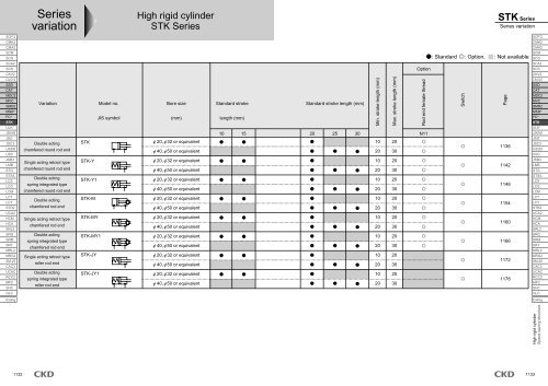
Series<br />
variation<br />
High rigid cylinder<br />
<strong>STK</strong> Series<br />
<strong>STK</strong> Series<br />
Series variation<br />
SCP*2<br />
CMK2<br />
CMA2<br />
SCM<br />
SCG<br />
SCA2<br />
SCS<br />
CKV2<br />
CA/OV2<br />
SSD<br />
CAT<br />
MDC2<br />
MVC<br />
SMD2<br />
MSD*<br />
FC*<br />
<strong>STK</strong><br />
ULK*<br />
JSK/M2<br />
JSG<br />
JSC3<br />
USSD<br />
USC<br />
JSB3<br />
LMB<br />
STG<br />
STS/L<br />
LCS<br />
LCG<br />
LCM<br />
LCT<br />
LCY<br />
STR2<br />
UCA2<br />
HCM<br />
HCA<br />
SRL2<br />
SRG<br />
SRM<br />
SRT<br />
MRL2<br />
MRG2<br />
SM-25<br />
CAC3<br />
UCAC<br />
RCC2<br />
MFC<br />
SHC<br />
GLC<br />
Variation<br />
Double acting<br />
chamfered round rod end<br />
Single acting retract type<br />
chamfered round rod end<br />
Double acting<br />
spring integrated type<br />
chamfered round rod end<br />
Double acting<br />
chamfered rod end<br />
Single acting retract type<br />
chamfered rod end<br />
Double acting<br />
spring integrated type<br />
chamfered rod end<br />
Single acting retract type<br />
roller rod end<br />
Double acting<br />
spring integrated type<br />
roller rod end<br />
Model no.<br />
JIS symbol<br />
<strong>STK</strong><br />
<strong>STK</strong>-Y<br />
<strong>STK</strong>-Y1<br />
<strong>STK</strong>-M<br />
<strong>STK</strong>-MY<br />
<strong>STK</strong>-MY1<br />
<strong>STK</strong>-JY<br />
<strong>STK</strong>-JY1<br />
Bore size<br />
(mm)<br />
20, 32 or equivalent<br />
40, 50 or equivalent<br />
20, 32 or equivalent<br />
40, 50 or equivalent<br />
20, 32 or equivalent<br />
40, 50 or equivalent<br />
20, 32 or equivalent<br />
40, 50 or equivalent<br />
20, 32 or equivalent<br />
40, 50 or equivalent<br />
20, 32 or equivalent<br />
40, 50 or equivalent<br />
20, 32 or equivalent<br />
40, 50 or equivalent<br />
20, 32 or equivalent<br />
40, 50 or equivalent<br />
Standard stroke<br />
length (mm)<br />
10 15<br />
Standard stroke length (mm)<br />
: Standard : Option, : Not available<br />
Option<br />
SCP*2<br />
CMK2<br />
CMA2<br />
SCM<br />
SCG<br />
SCA2<br />
SCS<br />
CKV2<br />
CA/OV2<br />
SSD<br />
CAT<br />
MDC2<br />
MVC<br />
SMD2<br />
MSD*<br />
FC*<br />
<strong>STK</strong><br />
ULK*<br />
JSK/M2<br />
JSG<br />
JSC3<br />
USSD<br />
USC<br />
JSB3<br />
LMB<br />
STG<br />
STS/L<br />
LCS<br />
LCG<br />
LCM<br />
LCT<br />
LCY<br />
STR2<br />
UCA2<br />
HCM<br />
HCA<br />
SRL2<br />
SRG<br />
SRM<br />
SRT<br />
MRL2<br />
MRG2<br />
SM-25<br />
CAC3<br />
UCAC<br />
RCC2<br />
MFC<br />
SHC<br />
GLC<br />
Ending<br />
Ending<br />
High rigid cylinder<br />
Space saving structure<br />
Min. stroke length (mm)<br />
Max. stroke length (mm)<br />
Rod end female thread<br />
Switch<br />
Page<br />
20 25 30 N11<br />
10 20<br />
1136<br />
20 30<br />
10 20<br />
1142<br />
20 30<br />
10 20<br />
1148<br />
20 30<br />
10 20<br />
1154<br />
20 30<br />
10 20<br />
1160<br />
20 30<br />
10 20<br />
1166<br />
20 30<br />
10 20<br />
1172<br />
20 30<br />
10 20<br />
1178<br />
20 30<br />
1132<br />
1133
SCP*2<br />
CMK2<br />
CMA2<br />
SCM<br />
SCG<br />
SCA2<br />
SCS<br />
CKV2<br />
CA/OV2<br />
SSD<br />
CAT<br />
MDC2<br />
MVC<br />
SMD2<br />
MSD*<br />
FC*<br />
<strong>STK</strong><br />
ULK*<br />
JSK/M2<br />
JSG<br />
JSC3<br />
USSD<br />
USC<br />
JSB3<br />
LMB<br />
STG<br />
STS/L<br />
LCS<br />
LCG<br />
LCM<br />
LCT<br />
LCY<br />
STR2<br />
UCA2<br />
HCM<br />
HCA<br />
SRL2<br />
SRG<br />
SRM<br />
SRT<br />
MRL2<br />
MRG2<br />
SM-25<br />
CAC3<br />
UCAC<br />
RCC2<br />
MFC<br />
SHC<br />
GLC<br />
Ending<br />
Pneumatic components<br />
Safety precautions<br />
Always read this section before starting use.<br />
Refer to Intro 71 for general precautions of the cylinder, and to Intro 78 for general precautions of<br />
the cylinder switch.<br />
High rigid cylinder <strong>STK</strong> Series<br />
1. Common<br />
CAUTION<br />
Braking a load coupled with a cylinder, etc., using<br />
the high rigid cylinder.<br />
The working range applies only when the pallet is stopped on<br />
the conveyor. When stopping a load coupled with a cylinder,<br />
etc., using the high rigid cylinder, the cylinder thrust acts as a<br />
lateral load. Select the cylinder so the allowable energy absorption<br />
and lateral load ranges are satisfied.<br />
1. Common<br />
CAUTION<br />
Do not apply torque to the piston rod. Install the piston<br />
rod with the rod contact surface parallel to the<br />
pallet contact surface so torque is not applied to the<br />
piston rod.<br />
Do not apply oil, etc., to the piston rod sliding section.<br />
The cylinder operation could fail, etc.<br />
The cylinder may malfunction if a magnetic substance,<br />
as a steel plate, is nearby. Move the magnetic<br />
substance to at least 10 mm from the cylinder.<br />
(Same clearance for all bore size)<br />
10mm and over<br />
Magnetized device such<br />
as steel plate, etc.<br />
Design & Selection<br />
Installation & Adjustment<br />
2. Single acting <strong>STK</strong>-Y<br />
CAUTION<br />
Do not pressurize from the single acting head side.<br />
If air is supplied from the head side for the single acting type,<br />
the air will leak.<br />
The Cylinder switch may malfunction if <strong>cylinders</strong> are<br />
installed adjacently. Separate <strong>cylinders</strong> by the following<br />
distances.<br />
(Same clearance for all bore size)<br />
20mm and over<br />
20mm and over<br />
Cylinder switch position<br />
10mm and over 10mm and over<br />
Cylinder switch position<br />
1134
<strong>STK</strong> Series<br />
2. Single acting <strong>STK</strong>-Y<br />
CAUTION<br />
Do not leave the single acting cylinder in the pressurized<br />
state. If left pressurized, the piston rod may not<br />
return with spring power when pressure is released.<br />
3. Chamfered rod end female thread<br />
<strong>STK</strong>-M-N11<br />
CAUTION<br />
Avoid using in methods that apply torque on the piston<br />
rod.<br />
The baffle spacer may deviate, and the orientation of the chamfered<br />
piston rod may change.<br />
1. Common<br />
CAUTION<br />
Usable pipe joints are limited, so see the following<br />
table to select the joint.<br />
Descriptions<br />
Bore size (mm)<br />
20<br />
32<br />
40<br />
50<br />
Port size<br />
M5<br />
A<br />
Rc1/8<br />
Rc1/4<br />
Port dimension<br />
A B<br />
8<br />
8<br />
12<br />
10.5<br />
B<br />
5.5<br />
8<br />
8.5<br />
10.5<br />
C<br />
Applicable joints<br />
SC3W-M5-4<br />
SC3W-M5-6<br />
GWS4-M5-S<br />
GWS4-M5<br />
GWL4-M5<br />
GWL6-M5<br />
SC3W-6-4/6/8<br />
GWS4-6 GWS6-6<br />
GWS8-6 GWL4-6<br />
GWL6-6<br />
SC3W-8-6/8/10<br />
GWS4-8 GWS6-8<br />
GWS10-8<br />
GWL4 to 12-8<br />
Joint O.D.<br />
C<br />
11<br />
or less<br />
15<br />
or less<br />
21<br />
or less<br />
When changing the direction of the baffle, loosen<br />
the 3 setscrews on the rod cover, change to the required<br />
position, then tighten again.<br />
2. Spring integrated double acting SKT-Y1<br />
CAUTION<br />
When using a double acting type with a spring, use<br />
only under normal conditions. If air is cut off, the rod<br />
is pushed to hold the stopper.<br />
During Use <br />
& Maintenance<br />
Inapplicable<br />
joints<br />
GWS6-M5<br />
GWS10-6<br />
GWL-8-6<br />
GWL10-6<br />
GWS-12-8<br />
When fixing a workpiece to the end of the piston rod,<br />
pull the piston rod into the stroke end. Then, attach a<br />
wrench to the section protruding outside the parallel<br />
section of the rod, and tighten while checking that<br />
tightening torque is not applied to the cylinder.<br />
SCP*2<br />
CMK2<br />
CMA2<br />
SCM<br />
SCG<br />
SCA2<br />
SCS<br />
CKV2<br />
CA/OV2<br />
SSD<br />
CAT<br />
MDC2<br />
MVC<br />
SMD2<br />
MSD*<br />
FC*<br />
<strong>STK</strong><br />
ULK*<br />
JSK/M2<br />
JSG<br />
JSC3<br />
USSD<br />
USC<br />
JSB3<br />
LMB<br />
STG<br />
STS/L<br />
LCS<br />
LCG<br />
LCM<br />
LCT<br />
LCY<br />
STR2<br />
UCA2<br />
HCM<br />
HCA<br />
SRL2<br />
SRG<br />
SRM<br />
SRT<br />
MRL2<br />
MRG2<br />
SM-25<br />
CAC3<br />
UCAC<br />
RCC2<br />
MFC<br />
SHC<br />
GLC<br />
Ending<br />
High rigid cylinder<br />
Space saving structure<br />
1135
SCP*2<br />
CMK2<br />
CMA2<br />
SCM<br />
SCG<br />
SCA2<br />
SCS<br />
CKV2<br />
CA/OV2<br />
SSD<br />
CAT<br />
MDC2<br />
MVC<br />
SMD2<br />
MSD*<br />
FC*<br />
<strong>STK</strong><br />
ULK*<br />
JSK/M2<br />
JSG<br />
JSC3<br />
USSD<br />
USC<br />
JSB3<br />
LMB<br />
STG<br />
STS/L<br />
LCS<br />
LCG<br />
LCM<br />
LCT<br />
LCY<br />
STR2<br />
UCA2<br />
HCM<br />
HCA<br />
SRL2<br />
SRG<br />
SRM<br />
SRT<br />
MRL2<br />
MRG2<br />
SM-25<br />
CAC3<br />
UCAC<br />
RCC2<br />
MFC<br />
SHC<br />
GLC<br />
Ending<br />
Specifications<br />
Descriptions<br />
Bore size<br />
Actuation<br />
Working fluid<br />
Max. working pressure<br />
Min. working pressure<br />
Guaranty durability pressure<br />
Ambient temperature<br />
Port size<br />
Stroke tolerance<br />
mm<br />
MPa<br />
MPa<br />
MPa<br />
mm<br />
Working piston speed mm/s<br />
Cushion<br />
Lubrication<br />
Rod end form<br />
Allowable energy absorption J<br />
Stroke length<br />
Bore size (mm)<br />
20<br />
32<br />
40<br />
50<br />
High rigid cylinder Double acting chamfered round rod end<br />
<strong>STK</strong> Series<br />
Bore size: 20, 32, 40, 50<br />
<strong>STK</strong><br />
20<br />
32<br />
40<br />
50<br />
Double acting<br />
Compressed air<br />
1.0<br />
0.15<br />
0.1<br />
M5<br />
1.6<br />
-10 to 60 (no freezing)<br />
Rc1/8<br />
+2.0<br />
0<br />
50 to 500<br />
Rubber cushioned<br />
Rc1/4<br />
Not required (when lubricating, use turbine oil Class 1 ISOVG 32)<br />
Round bar type<br />
Refer to page 1186.<br />
Stroke length (mm)<br />
10, 15, 20<br />
20, 25, 30<br />
Note: Other than standard stroke length is custom order.<br />
JIS symbol<br />
Double acting<br />
Max. stroke length (mm) Min. stroke length (mm) Min. stroke length with switch (mm)<br />
20<br />
10<br />
10<br />
30<br />
20<br />
20<br />
1136
<strong>STK</strong> Series<br />
Specifications<br />
Switch specifications<br />
1 color/2 color indicator<br />
Descriptions<br />
Applications<br />
Output method<br />
Power voltage<br />
Load voltage<br />
Load current<br />
Light<br />
Leakage current<br />
Cylinder weight table<br />
Stroke length<br />
Bore size<br />
20<br />
32<br />
40<br />
50<br />
Proximity 2 wire<br />
Proximity 3 wire<br />
Reed 2 wire<br />
T1H/T1 V<br />
T2H/T2V/ T2YH/ T3H/ T3PH/T3PV T3YH/<br />
T2JH/T2JV T2YV T3V (Custom order) T3YV<br />
TOH/TOV T5H/T5V T8H/T8V<br />
Programmable controller<br />
Programmable Programmable Programmable controller, Programmable controller,<br />
Programmable controller<br />
relay, IC circuit (w/o indicator light),<br />
relay, small solenoid valve<br />
controller, relay controller, relay serial connection<br />
relay<br />
-<br />
-<br />
NPN output PNP output NPN output<br />
10 to 28 VDC<br />
-<br />
-<br />
85 to 265 VAC 10 to 30 VDC 30 VDC or less 12/24 VDC 110 VAC 5/12/24 VDC 110 VAC 12/24 VDC 110 VAC 220 VAC<br />
5 to 100mA 5 to 20mA (Note 1) 100mA or less 50mA or less 5 to 50mA 7 to 20mA 50mA or less 20mA or less 5 to 50mA 7 to 20mA 7 to 10mA<br />
LED LED Red/green LED Green Red/green LED Without<br />
LED<br />
LED<br />
LED LED<br />
(ON lighting) (ON lighting) (ON lighting) (ON lighting) (ON lighting) (ON lighting) (ON lighting) indicator light (ON lighting)<br />
1mA or less with 100 VAC<br />
2mA or less with 200 VAC<br />
1mA or less 10 A or less 0mA<br />
With preventive maintenance output<br />
Descriptions<br />
Proximity 3 wire Proximity 4 wire Proximity 3 wire Proximity 4 wire<br />
T2YFH/V T3YFH/V T2YMH/V T3YMH/V<br />
Applications<br />
Output method<br />
Installation position adjustment section<br />
Programmable controller<br />
Programmable<br />
Programmable<br />
Programmable controller<br />
controller, relay<br />
controller, relay<br />
NPN output<br />
Red/green LED (ON lighting)<br />
Preventive maintenance output<br />
-<br />
Yellow LED (ON lighting)<br />
Power voltage<br />
Load voltage<br />
Load current<br />
Leakage current<br />
Load voltage<br />
-<br />
10 to 30 VDC<br />
5 to 20mA<br />
1mA or less<br />
10 to 28 VDC<br />
30 VDC or less<br />
50mA or less<br />
10 A or less<br />
30 VDC or less<br />
-<br />
10 to 30 VDC<br />
5 to 20mA<br />
1.2mA or less<br />
10 to 28 VDC<br />
30 VDC or less<br />
50mA or less<br />
10 A or less<br />
Load current<br />
Leakage current<br />
20mA or less<br />
50mA or less<br />
5 to 20mA or less<br />
10 A or less<br />
50mA or less<br />
Light<br />
Regular<br />
Output<br />
10 15 20 25 30<br />
214<br />
438<br />
-<br />
-<br />
229<br />
463<br />
-<br />
-<br />
243<br />
488<br />
793<br />
1285<br />
-<br />
-<br />
834<br />
1311<br />
-<br />
-<br />
875<br />
1337<br />
(g)<br />
Weight per<br />
switch (grommet)<br />
18<br />
SCP*2<br />
CMK2<br />
CMA2<br />
SCM<br />
SCG<br />
SCA2<br />
SCS<br />
CKV2<br />
CA/OV2<br />
SSD<br />
CAT<br />
MDC2<br />
MVC<br />
SMD2<br />
MSD*<br />
FC*<br />
<strong>STK</strong><br />
ULK*<br />
JSK/M2<br />
JSG<br />
JSC3<br />
USSD<br />
USC<br />
JSB3<br />
LMB<br />
STG<br />
STS/L<br />
LCS<br />
LCG<br />
LCM<br />
LCT<br />
LCY<br />
STR2<br />
UCA2<br />
HCM<br />
HCA<br />
SRL2<br />
SRG<br />
SRM<br />
SRT<br />
MRL2<br />
MRG2<br />
SM-25<br />
CAC3<br />
UCAC<br />
RCC2<br />
MFC<br />
SHC<br />
GLC<br />
Ending<br />
High rigid cylinder<br />
Space saving structure<br />
Preventive<br />
maintenance<br />
Output<br />
*The T0/T5 switch can be used with 220 VAC.<br />
Consult <strong>CKD</strong> for working conditions.<br />
Note 1: Refer to an Ending 1 page for other switches.<br />
Note 2: Max. load current: 20mA above is the value at 25 . When ambient temperature around switch is higher than 25 , the value is lower than 20mA.<br />
(5 to 10mA at 60 )<br />
1137
<strong>STK</strong> Series<br />
SCP*2<br />
CMK2<br />
CMA2<br />
SCM<br />
SCG<br />
SCA2<br />
SCS<br />
CKV2<br />
CA/OV2<br />
SSD<br />
CAT<br />
MDC2<br />
MVC<br />
SMD2<br />
MSD*<br />
FC*<br />
<strong>STK</strong><br />
ULK*<br />
JSK/M2<br />
JSG<br />
JSC3<br />
USSD<br />
USC<br />
JSB3<br />
LMB<br />
STG<br />
STS/L<br />
LCS<br />
LCG<br />
LCM<br />
LCT<br />
LCY<br />
STR2<br />
UCA2<br />
HCM<br />
HCA<br />
SRL2<br />
SRG<br />
SRM<br />
SRT<br />
MRL2<br />
MRG2<br />
SM-25<br />
CAC3<br />
UCAC<br />
RCC2<br />
MFC<br />
SHC<br />
GLC<br />
Ending<br />
How to order<br />
Without switch<br />
<strong>STK</strong><br />
With switch<br />
<strong>STK</strong><br />
20<br />
20<br />
A<br />
Bore size<br />
10<br />
10 T0H R<br />
B Port thread type<br />
C Stroke length<br />
Note on model no. selection<br />
Note 1: Switches other than (D) switch model no.<br />
are available. (Custom order)<br />
Refer to Ending 1 for the details.<br />
D Switch model no.<br />
Note 1<br />
N11<br />
N11<br />
E Switch quantity<br />
F Option<br />
A<br />
B<br />
C<br />
D<br />
E<br />
F<br />
Symbol<br />
Descriptions<br />
Bore size (mm)<br />
20<br />
20<br />
32<br />
32<br />
40<br />
40<br />
50<br />
50<br />
Port thread type<br />
Blank Rc thread<br />
NN NPT thread ( 32 and over) (custom order)<br />
GN G thread ( 32 and over) (custom order)<br />
Stroke length (mm)<br />
Bore size<br />
10 10<br />
15 15<br />
20 20<br />
25 25<br />
30 30<br />
Switch model no.<br />
Axial lead<br />
wire<br />
T0H* T0V*<br />
T5H* T5V*<br />
T8H* T8V*<br />
T1H* T1V*<br />
T2H* T2V*<br />
T3H* T3V*<br />
T3PH* T3PV*<br />
T2YH* T2YV*<br />
T3YH* T3YV*<br />
T2YFH* T2YFV*<br />
T3YFH* T3YFV*<br />
T2YMH* T2YMV*<br />
T3YMH* T3YMV*<br />
T2JH* T2JV*<br />
*Lead wire length (m)<br />
Blank<br />
3<br />
5<br />
Switch quantity<br />
R<br />
H<br />
D<br />
Option<br />
Blank<br />
N11<br />
Radial lead<br />
wire<br />
1m (standard)<br />
3m (option)<br />
5m (option)<br />
20<br />
One on rod end<br />
One on head end<br />
2<br />
Without rod end thread<br />
Rod end female thread<br />
32<br />
40 50<br />
Contact<br />
Lead<br />
Indicator<br />
wire<br />
1 color indicator type<br />
Without indicator light 2-wire<br />
1 color indicator type<br />
2-wire<br />
1 color indicator type<br />
3-wire<br />
1 color indicator type (custom order)<br />
2-wire<br />
2 color indicator type<br />
3-wire<br />
2 color indicator type 3-wire<br />
(without indicator light for<br />
preventive maintenance output) 4-wire<br />
2 color indicator type 3-wire<br />
(with indicator light for preventive<br />
maintenance output (1 color)) 4-wire<br />
Off-delay type 2-wire<br />
Reed<br />
Proximity<br />
1138<br />
<br />
<strong>STK</strong>-20-10-T0H-R-N11<br />
Model: High rigid cylinder double acting chamfered round rod end<br />
A Bore size : 20mm<br />
B Port thread type : Rc thread<br />
C Stroke length : 10mm<br />
D Switch model no. : Reed T0H switch, lead wire 1m<br />
E Switch quantity : One on rod end<br />
F Option : With rod end female thread<br />
How to order switch<br />
SW T0H<br />
Switch model no.<br />
(Item D above)
Internal structure and parts list<br />
N0. Parts name Material Remarks<br />
1<br />
2<br />
3<br />
4<br />
5<br />
6<br />
7<br />
8<br />
<strong>STK</strong>-20<br />
<strong>STK</strong>-32/40/50<br />
Piston rod<br />
Bush<br />
Rod cover<br />
Rod packing seal<br />
Hexagon socket head set screw<br />
Metal gasket<br />
Cushion rubber (R)<br />
Spacer washer<br />
Repair parts list<br />
Bore size<br />
(mm)<br />
20<br />
32<br />
40<br />
50<br />
Kit No.<br />
<strong>STK</strong>-20K<br />
<strong>STK</strong>-32K<br />
<strong>STK</strong>-40K<br />
<strong>STK</strong>-50K<br />
1 2 3 4 5 6 7 8 9 10 11 12 13 14 15 16<br />
1 2 3 4 5 6 7 8 9 10 11 12 13 14 15 16<br />
20: Stainless steel<br />
32 to 50: Steel<br />
Oilless dry met<br />
Aluminum alloy<br />
Nitrile rubber<br />
Steel<br />
Nitrile rubber<br />
Urethane rubber<br />
Stainless steel<br />
Industrial<br />
chrome plating<br />
Alumite<br />
Repair parts number<br />
4 6 11<br />
13 14<br />
Blackening<br />
NO. Parts name Material Remarks<br />
9<br />
10<br />
11<br />
12<br />
13<br />
14<br />
15<br />
16<br />
Spacer<br />
Magnet<br />
Piston packing seal<br />
Piston<br />
Wear ring<br />
Cushion rubber (H)<br />
Body<br />
Guard<br />
<strong>STK</strong> Series<br />
Internal structure and parts list<br />
Polyamide<br />
Plastic<br />
Nitrile rubber<br />
Aluminum alloy<br />
Acetar resin<br />
Urethane rubber<br />
Aluminum alloy<br />
20: Stainless steel<br />
32 to 50: Aluminum alloy<br />
Chromate<br />
Hard alumite<br />
32 to 50: Chromate<br />
1139<br />
SCP*2<br />
CMK2<br />
CMA2<br />
SCM<br />
SCG<br />
SCA2<br />
SCS<br />
CKV2<br />
CA/OV2<br />
SSD<br />
CAT<br />
MDC2<br />
MVC<br />
SMD2<br />
MSD*<br />
FC*<br />
<strong>STK</strong><br />
ULK*<br />
JSK/M2<br />
JSG<br />
JSC3<br />
USSD<br />
USC<br />
JSB3<br />
LMB<br />
STG<br />
STS/L<br />
LCS<br />
LCG<br />
LCM<br />
LCT<br />
LCY<br />
STR2<br />
UCA2<br />
HCM<br />
HCA<br />
SRL2<br />
SRG<br />
SRM<br />
SRT<br />
MRL2<br />
MRG2<br />
SM-25<br />
CAC3<br />
UCAC<br />
RCC2<br />
MFC<br />
SHC<br />
GLC<br />
Ending<br />
High rigid cylinder<br />
Space saving structure
<strong>STK</strong> Series<br />
SCP*2<br />
Dimensions<br />
CMK2<br />
CMA2<br />
<strong>STK</strong>-20<br />
SCM<br />
SCG<br />
SCA2<br />
SCS<br />
CKV2<br />
CA/OV2<br />
SSD<br />
CAT<br />
MDC2<br />
MVC<br />
SMD2<br />
36<br />
25.5<br />
18.5<br />
Stroke length<br />
22<br />
67 + (2 x stroke length)<br />
67 + stroke length<br />
20<br />
45 + stroke length<br />
5.5<br />
2-M5 x 0.8<br />
MSD*<br />
FC*<br />
<strong>STK</strong><br />
HD<br />
ULK*<br />
JSK/M2<br />
36<br />
25.5<br />
12.5<br />
24<br />
12<br />
JSG<br />
JSC3<br />
USSD<br />
USC<br />
JSB3<br />
47<br />
8-9 spot face depth 5.5<br />
22 (width across flats) 11<br />
RD<br />
5.5<br />
8-M6<br />
depth 11<br />
LMB<br />
STG<br />
STS/L<br />
LCS<br />
LCG<br />
LCM<br />
LCT<br />
LCY<br />
STR2<br />
<strong>STK</strong>-20-N11<br />
(Dimensions other than listed are same as above (<strong>STK</strong>-20) dimensions.)<br />
UCA2<br />
HCM<br />
HCA<br />
SRL2<br />
SRG<br />
SRM<br />
72 + (2 x stroke length)<br />
SRT<br />
Stroke length<br />
72 + stroke length<br />
MRL2<br />
MRG2<br />
SM-25<br />
CAC3<br />
M5<br />
depth 7<br />
27<br />
22<br />
UCAC<br />
RCC2<br />
MFC<br />
SHC<br />
GLC<br />
Ending<br />
10<br />
Dimensions with switch<br />
Bore Reed T0H/T0V/T5H/T5V Proximity T2H/T2V/T3H/T3V<br />
size HD RD HD RD<br />
20 5.5 21 5.5 21<br />
Note : Refer to page 1183 for the HD, RD, and projecting dimensions of<br />
the 2 color indication type, off delay type, T1*, T8* switch.<br />
1140
I<br />
<strong>STK</strong> Series<br />
Double acting chamfered round rod end<br />
Dimensions<br />
SCP*2<br />
<strong>STK</strong>-32/40/50<br />
CMK2<br />
CMA2<br />
SCM<br />
SCG<br />
G<br />
F O<br />
N<br />
b<br />
F<br />
N<br />
H<br />
L<br />
a<br />
FB<br />
Stroke length<br />
P<br />
MM<br />
V<br />
A + (2 x stroke length)<br />
A + stroke length<br />
B + stroke length<br />
C<br />
a<br />
b<br />
D<br />
HD<br />
2-EE<br />
SCA2<br />
SCS<br />
CKV2<br />
CA/OV2<br />
SSD<br />
CAT<br />
MDC2<br />
MVC<br />
SMD2<br />
MSD*<br />
FC*<br />
<strong>STK</strong><br />
ULK*<br />
JSK/M2<br />
K<br />
M (Width across flats)<br />
8-J installation hole<br />
U<br />
RD<br />
8-KA<br />
JSG<br />
JSC3<br />
FA<br />
USSD<br />
USC<br />
JSB3<br />
LMB<br />
STG<br />
<strong>STK</strong>-32/40/50-N11<br />
(Dimensions other than listed are same as above (<strong>STK</strong>-32/40/50) dimensions.)<br />
STS/L<br />
LCS<br />
LCG<br />
LCM<br />
LCT<br />
LCY<br />
b<br />
a<br />
Stroke length<br />
KK<br />
X<br />
V<br />
Y + (2 x mm stroke)<br />
Y + stroke length<br />
a<br />
b<br />
STR2<br />
UCA2<br />
HCM<br />
HCA<br />
SRL2<br />
SRG<br />
SRM<br />
SRT<br />
MRL2<br />
MRG2<br />
SM-25<br />
CAC3<br />
UCAC<br />
RCC2<br />
MN<br />
MFC<br />
SHC<br />
GLC<br />
Ending<br />
Symbol<br />
Bore size<br />
32<br />
40<br />
50<br />
A<br />
68<br />
B C D EE F<br />
48<br />
20<br />
8<br />
80.5 52.5 24.5 8.5<br />
82 54 24.5 10.5<br />
Rc1/8<br />
Rc1/8<br />
Rc1/4<br />
FA<br />
FB G H I J K KA KK L M MM MN N O P U V X Y<br />
45 23 20.5 49.5 24 5.5<br />
52<br />
64<br />
26.5 27.5 57<br />
32.5 28.5 71<br />
24 5.5<br />
33 6.9<br />
Dimensions with switch<br />
Bore Reed T0H/T0V/T5H/T5V Proximity T2H/T2V/T3H/T3V<br />
size HD RD HD RD<br />
32 9.5 21<br />
9 21<br />
40 10.5 24 10.5 24<br />
50 11.5 24 11.5 24<br />
9 spot face<br />
depth 5.5<br />
9 spot face<br />
depth 5.5<br />
11 spot face<br />
depth 6.5<br />
60 M6 depth 11 M8 depth 13 10<br />
69 M6 depth 11 M8 depth 13 10<br />
86 M8 depth 13 M10 depth 15 15<br />
32<br />
41<br />
50<br />
20<br />
25<br />
30<br />
17 34 4.5 36 13<br />
22 40 5 44 15<br />
27 50 7 56 15<br />
20<br />
28<br />
28<br />
30<br />
38<br />
43<br />
Note : Refer to page 1183 for the HD, RD, and projecting dimensions of<br />
the 2 color indication type, off delay type, T1*, T8* switch.<br />
78<br />
90.5<br />
97<br />
High rigid cylinder<br />
Space saving structure<br />
1141
SCP*2<br />
CMK2<br />
CMA2<br />
SCM<br />
SCG<br />
SCA2<br />
SCS<br />
CKV2<br />
CA/OV2<br />
SSD<br />
CAT<br />
MDC2<br />
MVC<br />
SMD2<br />
MSD*<br />
FC*<br />
<strong>STK</strong><br />
ULK*<br />
JSK/M2<br />
JSG<br />
JSC3<br />
USSD<br />
USC<br />
JSB3<br />
LMB<br />
STG<br />
STS/L<br />
LCS<br />
LCG<br />
LCM<br />
LCT<br />
LCY<br />
STR2<br />
UCA2<br />
HCM<br />
HCA<br />
SRL2<br />
SRG<br />
SRM<br />
SRT<br />
MRL2<br />
MRG2<br />
SM-25<br />
CAC3<br />
UCAC<br />
RCC2<br />
MFC<br />
SHC<br />
GLC<br />
Ending<br />
Specifications<br />
Descriptions<br />
Bore size<br />
mm<br />
Actuation<br />
Working fluid<br />
Max. working pressure MPa<br />
Min. working pressure MPa<br />
Withstanding pressure MPa<br />
Ambient temperature<br />
Port size<br />
Stroke tolerance mm<br />
Working piston speed mm/s<br />
Cushion<br />
Lubrication<br />
Rod end form<br />
Allowable energy absorption J<br />
Stroke length<br />
Bore size (mm)<br />
20<br />
32<br />
40<br />
50<br />
Spring load<br />
JIS symbol<br />
<strong>STK</strong>-Y<br />
20<br />
32<br />
40<br />
50<br />
Single acting retract type<br />
Compressed air<br />
1.0<br />
0.22<br />
0.12<br />
M5<br />
1.6<br />
-10 to 60 (no freezing)<br />
Rc1/8<br />
+2.0<br />
0<br />
50 to 500<br />
Rubber cushioned<br />
Rc1/4<br />
Not required (when lubricating, use turbine oil Class 1 ISOVG 32)<br />
Round bar type<br />
Refer to page 1186.<br />
Stroke length (mm)<br />
10, 15, 20<br />
20, 25, 30<br />
Note: Other than standard stroke length is custom order.<br />
Bore size (mm)<br />
20<br />
<br />
<br />
32<br />
<br />
<br />
40<br />
<br />
<br />
50<br />
High rigid cylinder Single acting retract type chamfered round rod end<br />
<strong>STK</strong>-Y Series<br />
Bore size: 20, 32, 40, 50<br />
Max. stroke length (mm)<br />
20<br />
30<br />
Single acting retract type<br />
Min. stroke length (mm)<br />
10<br />
20<br />
Min. stroke length with switch (mm)<br />
10<br />
(Unit: N)<br />
Stroke length (mm) Stroke length 0 Full stroke length during operation<br />
10<br />
11.5<br />
15<br />
9.9<br />
14.7<br />
20<br />
8.2<br />
10<br />
24.5<br />
15<br />
21.1<br />
31.4<br />
20<br />
17.6<br />
20<br />
29.0<br />
25<br />
25.3<br />
44.4<br />
30<br />
21.5<br />
20<br />
55.4<br />
25<br />
48.0<br />
84.8<br />
30<br />
40.7<br />
20<br />
1142
<strong>STK</strong>-Y Series<br />
Specifications<br />
Switch specifications<br />
1 color/2 color indicator<br />
Descriptions<br />
Applications<br />
Output method<br />
Power voltage<br />
Load voltage<br />
Load current<br />
Light<br />
Leakage current<br />
Cylinder weight table<br />
Stroke length<br />
Bore size<br />
20<br />
32<br />
40<br />
50<br />
Proximity 2 wire<br />
Proximity 3 wire<br />
Reed 2 wire<br />
T1H/T1 V<br />
T2H/T2V/ T2YH/ T3H/ T3PH/T3PV T3YH/<br />
T2JH/T2JV T2YV T3V (Custom order) T3YV<br />
TOH/TOV T5H/T5V T8H/T8V<br />
Programmable controller<br />
Programmable Programmable Programmable controller, Programmable controller,<br />
Programmable controller<br />
relay, IC circuit (w/o indicator light),<br />
relay, small solenoid valve<br />
controller, relay controller, relay serial connection relay<br />
-<br />
-<br />
NPN output PNP output NPN output<br />
10 to 28 VDC<br />
-<br />
-<br />
85 to 265 VAC 10 to 30 VDC 30 VDC or less 12/24 VDC 110 VAC 5/12/24 VDC 110 VAC 12/24 VDC 110 VAC 220 VAC<br />
5 to 100mA 5 to 20mA (Note 1) 100mA or less 50mA or less 5 to 50mA 7 to 20mA 50mA or less 20mA or less 5 to 50mA 7 to 20mA 7 to 10mA<br />
LED LED Red/green LED Green Red/green LED Without<br />
LED<br />
LED<br />
LED LED<br />
(ON lighting) (ON lighting) (ON lighting) (ON lighting) (ON lighting) (ON lighting) (ON lighting) indicator light (ON lighting)<br />
1mA or less with 100 VAC<br />
2mA or less with 200 VAC<br />
1mA or less 10 A or less 0mA<br />
With preventive maintenance output<br />
Descriptions<br />
Proximity 3 wire Proximity 4 wire Proximity 3 wire Proximity 4 wire<br />
T2YFH/V T3YFH/V T2YMH/V T3YMH/V<br />
Applications<br />
Output method<br />
Installation position adjustment section<br />
Programmable controller<br />
Programmable<br />
Programmable<br />
Programmable controller<br />
controller, relay<br />
controller, relay<br />
NPN output<br />
Red/green LED (ON lighting)<br />
Preventive maintenance output<br />
-<br />
Yellow LED (ON lighting)<br />
Power voltage<br />
Load voltage<br />
Load current<br />
Leakage current<br />
Load voltage<br />
-<br />
10 to 30 VDC<br />
5 to 20mA<br />
1mA or less<br />
10 to 28 VDC<br />
30 VDC or less<br />
50mA or less<br />
10 A or less<br />
30 VDC or less<br />
-<br />
10 to 30 VDC<br />
5 to 20mA<br />
1.2mA or less<br />
10 to 28 VDC<br />
30 VDC or less<br />
50mA or less<br />
10 A or less<br />
Load current<br />
Leakage current<br />
20mA or less<br />
50mA or less<br />
5 to 20mA or less<br />
10 A or less<br />
50mA or less<br />
Light<br />
Regular<br />
Output<br />
Preventive<br />
maintenance<br />
Output<br />
10<br />
217<br />
454<br />
-<br />
-<br />
15<br />
232<br />
479<br />
-<br />
-<br />
20<br />
246<br />
504<br />
809<br />
1299<br />
25<br />
-<br />
-<br />
850<br />
1325<br />
*The T0/T5 switch can be used with 220 VAC.<br />
Consult <strong>CKD</strong> for working conditions.<br />
Note 1: Refer to Ending 1 for other switches.<br />
Note 2: Max. load current: 20mA above is the value at 25 . When ambient temperature around switch is higher than 25 , the value is lower than 20mA.<br />
(5 to 10mA at 60 )<br />
30<br />
-<br />
-<br />
891<br />
1351<br />
Weight per switch<br />
(grommet)<br />
18<br />
(g)<br />
SCP*2<br />
CMK2<br />
CMA2<br />
SCM<br />
SCG<br />
SCA2<br />
SCS<br />
CKV2<br />
CA/OV2<br />
SSD<br />
CAT<br />
MDC2<br />
MVC<br />
SMD2<br />
MSD*<br />
FC*<br />
<strong>STK</strong><br />
ULK*<br />
JSK/M2<br />
JSG<br />
JSC3<br />
USSD<br />
USC<br />
JSB3<br />
LMB<br />
STG<br />
STS/L<br />
LCS<br />
LCG<br />
LCM<br />
LCT<br />
LCY<br />
STR2<br />
UCA2<br />
HCM<br />
HCA<br />
SRL2<br />
SRG<br />
SRM<br />
SRT<br />
MRL2<br />
MRG2<br />
SM-25<br />
CAC3<br />
UCAC<br />
RCC2<br />
MFC<br />
SHC<br />
GLC<br />
Ending<br />
High rigid cylinder<br />
Space saving structure<br />
1143
<strong>STK</strong>-Y Series<br />
SCP*2<br />
CMK2<br />
CMA2<br />
SCM<br />
SCG<br />
SCA2<br />
SCS<br />
CKV2<br />
CA/OV2<br />
SSD<br />
CAT<br />
MDC2<br />
MVC<br />
SMD2<br />
MSD*<br />
FC*<br />
<strong>STK</strong><br />
ULK*<br />
JSK/M2<br />
JSG<br />
JSC3<br />
USSD<br />
USC<br />
JSB3<br />
LMB<br />
STG<br />
STS/L<br />
LCS<br />
LCG<br />
LCM<br />
LCT<br />
LCY<br />
STR2<br />
UCA2<br />
HCM<br />
HCA<br />
SRL2<br />
SRG<br />
SRM<br />
SRT<br />
MRL2<br />
MRG2<br />
SM-25<br />
CAC3<br />
UCAC<br />
RCC2<br />
MFC<br />
SHC<br />
GLC<br />
Ending<br />
1144<br />
How to order<br />
Without switch<br />
<strong>STK</strong>-Y<br />
With switch<br />
<strong>STK</strong>-Y<br />
20<br />
20<br />
10<br />
<br />
<strong>STK</strong>-Y-20-10-T0H-R-N11<br />
A<br />
Bore size<br />
10 T0H R<br />
Note on model no. selection<br />
Model: High rigid cylinder single acting retract type<br />
chamfered round rod end<br />
A Bore size : 20mm<br />
B Port thread type : Rc thread<br />
C Stroke length : 10mm<br />
D Switch model no. : Reed T0H switch,<br />
lead wire 1m<br />
E Switch quantity : One on rod end<br />
F Option : With rod end female thread<br />
B<br />
Port thread type<br />
Note 1: Switches other than (D) switch model no.<br />
are also available. (Custom order)<br />
Refer to Ending 1 for the details.<br />
C<br />
Stroke length<br />
D<br />
Switch model no.<br />
Note 1<br />
N11<br />
N11<br />
E Switch<br />
quantity<br />
F Option<br />
Symbol<br />
A Bore size (mm)<br />
20<br />
20<br />
32<br />
32<br />
40<br />
40<br />
50<br />
50<br />
B<br />
C<br />
D<br />
E<br />
F<br />
Stroke length<br />
Bore size<br />
10<br />
10<br />
15<br />
15<br />
20<br />
20<br />
25<br />
25<br />
30<br />
30<br />
Switch model no.<br />
Axial lead<br />
wire<br />
T0H* T0V*<br />
T5H* T5V*<br />
T8H* T8V*<br />
T1H* T1V*<br />
T2H* T2V*<br />
T3H* T3V*<br />
T3PH* T3PV*<br />
T2YH* T2YV*<br />
T3YH* T3YV*<br />
T2YFH* T2YFV*<br />
T3YFH* T3YFV*<br />
T2YMH* T2YMV*<br />
T3YMH* T3YMV*<br />
T2JH* T2JV*<br />
*Lead wire length (m)<br />
How to order switch<br />
SW T0H<br />
Switch model no.<br />
(Item D above)<br />
20<br />
Descriptions<br />
Port thread type<br />
Blank Rc thread<br />
NN NPT thread ( 32 and over) (custom order)<br />
GN G thread ( 32 and over) (custom order)<br />
Blank<br />
3<br />
5<br />
32<br />
Switch quantity<br />
R<br />
One on rod end on rod end<br />
H<br />
One on rod end on head end<br />
D<br />
2<br />
Option<br />
Blank<br />
N11<br />
Radial lead<br />
wire<br />
1m (standard)<br />
3m (option)<br />
5m (option)<br />
Contact<br />
Reed<br />
Proximity<br />
Without rod end thread<br />
Rod end female thread<br />
40 50<br />
Lead<br />
Indicator<br />
wire<br />
1 color indicator type<br />
Without indicator light 2-wire<br />
1 color indicator type<br />
2-wire<br />
1 color indicator type<br />
3-wire<br />
1 color indicator type (custom order)<br />
2-wire<br />
2 color indicator type<br />
3-wire<br />
2 color indicator type 3-wire<br />
(without indicator light for<br />
preventive maintenance output) 4-wire<br />
2 color indicator type 3-wire<br />
(with indicator light for preventive<br />
maintenance output (1 color)) 4-wire<br />
Off-delay type 2-wire
Internal structure and parts list<br />
N0. Parts name Material Remarks<br />
1<br />
2<br />
3<br />
4<br />
5<br />
6<br />
7<br />
8<br />
9<br />
<strong>STK</strong>-Y-20<br />
<strong>STK</strong>-Y-32/40/50<br />
Piston rod<br />
Bush<br />
Rod cover<br />
Rod packing seal<br />
Hexagon socket head set screw<br />
Metal gasket<br />
Cushion rubber (R)<br />
Spacer<br />
Magnet<br />
Repair parts list<br />
Bore size<br />
(mm)<br />
20<br />
32<br />
40<br />
50<br />
Kit No.<br />
<strong>STK</strong>-Y-20K<br />
<strong>STK</strong>-Y-32K<br />
<strong>STK</strong>-Y-40K<br />
<strong>STK</strong>-Y-50K<br />
1 2 3 4 5 6 7 8 9 10 11 13 15 14 16 17<br />
1 2 3 4 5 6 7 8 9 10 11 12 13 15 14 16 17<br />
20: Stainless steel<br />
32 to 50: Steel<br />
Oilless dry met<br />
Aluminum alloy<br />
Nitrile rubber<br />
Steel<br />
Nitrile rubber<br />
Urethane rubber<br />
Aluminum alloy<br />
Plastic<br />
Industrial chrome plating<br />
Alumite<br />
Repair parts number<br />
4 6 10<br />
12 13<br />
Blackening<br />
Chromate<br />
NO. Parts name Material Remarks<br />
10<br />
11<br />
12<br />
13<br />
14<br />
15<br />
16<br />
17<br />
18<br />
Piston packing seal<br />
Piston<br />
Wear ring<br />
Cushion rubber (H)<br />
Stainless steel wire net<br />
Plug<br />
Body<br />
Cover<br />
Coil spring<br />
18<br />
18<br />
<strong>STK</strong>-Y Series<br />
Internal structure and parts list<br />
Nitrile rubber<br />
Aluminum alloy<br />
Acetar resin<br />
Urethane rubber<br />
Stainless steel<br />
Stainless steel<br />
Aluminum alloy<br />
20: Steel<br />
32 to 50: Aluminum alloy<br />
Steel<br />
Chromate<br />
Hard alumite<br />
20: Galvanizing<br />
32 to 50: Chromate<br />
Electrode position coating<br />
1145<br />
SCP*2<br />
CMK2<br />
CMA2<br />
SCM<br />
SCG<br />
SCA2<br />
SCS<br />
CKV2<br />
CA/OV2<br />
SSD<br />
CAT<br />
MDC2<br />
MVC<br />
SMD2<br />
MSD*<br />
FC*<br />
<strong>STK</strong><br />
ULK*<br />
JSK/M2<br />
JSG<br />
JSC3<br />
USSD<br />
USC<br />
JSB3<br />
LMB<br />
STG<br />
STS/L<br />
LCS<br />
LCG<br />
LCM<br />
LCT<br />
LCY<br />
STR2<br />
UCA2<br />
HCM<br />
HCA<br />
SRL2<br />
SRG<br />
SRM<br />
SRT<br />
MRL2<br />
MRG2<br />
SM-25<br />
CAC3<br />
UCAC<br />
RCC2<br />
MFC<br />
SHC<br />
GLC<br />
Ending<br />
High rigid cylinder<br />
Space saving structure
<strong>STK</strong>-Y Series<br />
SCP*2<br />
Dimensions<br />
CMK2<br />
CMA2<br />
<strong>STK</strong>-Y-20<br />
SCM<br />
SCG<br />
SCA2<br />
SCS<br />
CKV2<br />
CA/OV2<br />
SSD<br />
36<br />
67 + (2 x stroke length)<br />
CAT<br />
25.5<br />
Stroke length<br />
67 + stroke length<br />
MDC2<br />
MVC<br />
SMD2<br />
18.5<br />
22<br />
20<br />
45 + stroke length<br />
5.5<br />
2-M5<br />
MSD*<br />
FC*<br />
<strong>STK</strong><br />
HD<br />
ULK*<br />
JSK/M2<br />
36<br />
25.5<br />
12.5<br />
24<br />
12<br />
JSG<br />
JSC3<br />
USSD<br />
USC<br />
JSB3<br />
47<br />
8-9 spot face depth 5.5<br />
22 (width across flats) 11<br />
RD<br />
5.5<br />
8-M6<br />
Depth 11<br />
LMB<br />
STG<br />
STS/L<br />
LCS<br />
LCG<br />
LCM<br />
LCT<br />
LCY<br />
STR2<br />
<strong>STK</strong>-Y-20-N11<br />
(Dimensions other than listed are same as above (<strong>STK</strong>-Y-20) dimensions.)<br />
UCA2<br />
HCM<br />
HCA<br />
SRL2<br />
SRG<br />
SRM<br />
SRT<br />
72 + (2 x stroke length)<br />
MRL2<br />
MRG2<br />
SM-25<br />
CAC3<br />
UCAC<br />
Stroke length<br />
M5<br />
Depth 7<br />
27<br />
22<br />
72 + stroke length<br />
RCC2<br />
MFC<br />
SHC<br />
GLC<br />
Ending<br />
10<br />
Dimensions with switch<br />
Bore Reed T0H/T0V/T5H/T5V Proximity T2H/T2V/T3H/T3V<br />
size HD RD HD RD<br />
20 7 19.5 7 19.5<br />
Note : Refer to page 1184 for the HD, RD, and projecting dimensions of<br />
the 2 color indication type, off delay type, T1*, T8* switch.<br />
1146
I<br />
Dimensions<br />
<strong>STK</strong>-Y-32/40/50<br />
G<br />
F O<br />
K<br />
N<br />
<strong>STK</strong>-Y-32/40/50-N11<br />
b<br />
F<br />
M (width across flats)<br />
8-J installation hole<br />
P<br />
(Dimensions other than listed are same as above (<strong>STK</strong>-Y-32/40/50) dimensions.)<br />
b<br />
N<br />
H<br />
L<br />
MN<br />
a<br />
a<br />
FA<br />
FB<br />
Stroke length<br />
MM<br />
Stroke length<br />
KK<br />
<strong>STK</strong>-Y Series<br />
Single acting retract type chamfered round rod end<br />
U<br />
X<br />
V<br />
V<br />
A + (2 x stroke length)<br />
A + stroke length<br />
RD<br />
C<br />
B + stroke length<br />
a<br />
Y + (2 x stroke length)<br />
Y + stroke length<br />
a<br />
b<br />
b<br />
D<br />
HD<br />
8-KA<br />
2-EE<br />
SCP*2<br />
CMK2<br />
CMA2<br />
SCM<br />
SCG<br />
SCA2<br />
SCS<br />
CKV2<br />
CA/OV2<br />
SSD<br />
CAT<br />
MDC2<br />
MVC<br />
SMD2<br />
MSD*<br />
FC*<br />
<strong>STK</strong><br />
ULK*<br />
JSK/M2<br />
JSG<br />
JSC3<br />
USSD<br />
USC<br />
JSB3<br />
LMB<br />
STG<br />
STS/L<br />
LCS<br />
LCG<br />
LCM<br />
LCT<br />
LCY<br />
STR2<br />
UCA2<br />
HCM<br />
HCA<br />
SRL2<br />
SRG<br />
SRM<br />
SRT<br />
MRL2<br />
MRG2<br />
SM-25<br />
CAC3<br />
UCAC<br />
RCC2<br />
MFC<br />
SHC<br />
GLC<br />
Ending<br />
Symbol<br />
Bore size size A B C D EE EE F FFAGFB HG IH I J J K KKA KA KK KK L LM MMMMMNMNNN OO PP U V X Y<br />
32 68 48 20 8 Rc1/8 45 23 20.5 49.5 24 5.5<br />
9 spot face<br />
depth 5.5 60 M6 depth 11 M8 depth 13 10 32 20 17 34 4.5 36 13 20 30 78<br />
40 80.5 52.5 24.5 8.5 Rc1/8 52 26.5 27.5 57 24 5.5<br />
9 spot face<br />
depth 5.5 69 M6 depth 11 M8 depth 13 10 41 25 22 40 5 44 15 28 38 90.5<br />
50 82 54 24.5 10.5 Rc1/4 64 32.5 28.5 71 33 6.9<br />
11 spot face<br />
depth 6.5 86 M8 depth 13 M10 depth 15 15 50 30 27 50 7 56 15 28 43 97<br />
Dimensions with switch<br />
Bore Reed T0H/T0V/T5H/T5V Proximity T2H/T2V/T3H/T3V<br />
size HD RD HD RD<br />
32 10.5 20 10.5<br />
20<br />
40 11.5 23 11.5<br />
23<br />
Note : Refer to page 1184 for the HD, RD, and projecting dimensions of<br />
50 12.5 23 12.5<br />
23<br />
the 2 color indication type, off delay type, T1*, T8* switch.<br />
High rigid cylinder<br />
Space saving structure<br />
1147
SCP*2<br />
CMK2<br />
CMA2<br />
SCM<br />
SCG<br />
SCA2<br />
SCS<br />
CKV2<br />
CA/OV2<br />
SSD<br />
CAT<br />
MDC2<br />
MVC<br />
SMD2<br />
MSD*<br />
FC*<br />
<strong>STK</strong><br />
ULK*<br />
JSK/M2<br />
JSG<br />
JSC3<br />
USSD<br />
USC<br />
JSB3<br />
LMB<br />
STG<br />
STS/L<br />
LCS<br />
LCG<br />
LCM<br />
LCT<br />
LCY<br />
STR2<br />
UCA2<br />
HCM<br />
HCA<br />
SRL2<br />
SRG<br />
SRM<br />
SRT<br />
MRL2<br />
MRG2<br />
SM-25<br />
CAC3<br />
UCAC<br />
RCC2<br />
MFC<br />
SHC<br />
GLC<br />
Ending<br />
Specifications<br />
Descriptions<br />
Bore size<br />
mm<br />
Actuation<br />
Working fluid<br />
Max. working pressure MPa<br />
Min. working pressure MPa<br />
Withstanding pressure MPa<br />
Ambient temperature<br />
Port size<br />
Stroke tolerance mm<br />
Working piston speed mm/s<br />
Cushion<br />
Lubrication<br />
Rod end form<br />
Allowable energy absorption J<br />
Stroke length<br />
Bore size (mm)<br />
20<br />
32<br />
40<br />
50<br />
Spring load<br />
JIS symbol<br />
<strong>STK</strong>-Y1<br />
20<br />
32<br />
40<br />
50<br />
Double acting spring integrated type<br />
Compressed air<br />
1.0<br />
0.22<br />
0.12<br />
M5<br />
1.6<br />
-10 to 60 (no freezing)<br />
Rc1/8<br />
+2.0<br />
0<br />
50 to 500<br />
Rubber cushioned<br />
Rc1/4<br />
Not required (when lubricating, use turbine oil Class 1 ISOVG 32)<br />
Round bar type<br />
Refer to page 1186.<br />
Stroke length (mm)<br />
10, 15, 20<br />
20, 25, 30<br />
Note: Other than standard stroke length is custom order.<br />
Bore size (mm)<br />
20<br />
32<br />
40<br />
50<br />
High rigid cylinder Double acting spring integrated type chamfered round rod end<br />
<strong>STK</strong>-Y1 Series<br />
Bore size: 20, 32, 40, 50<br />
Max. stroke length (mm)<br />
20<br />
30<br />
Double acting spring integrated type<br />
Min. stroke length (mm)<br />
10<br />
20<br />
Min. stroke length with switch (mm)<br />
10<br />
(Unit: N)<br />
Stroke length (mm) Stroke length 0 Full stroke length during operation<br />
10<br />
11.5<br />
15<br />
9.9<br />
14.7<br />
20<br />
8.2<br />
10<br />
24.5<br />
15<br />
21.1<br />
31.4<br />
20<br />
17.6<br />
20<br />
29.0<br />
25<br />
25.3<br />
44.4<br />
30<br />
21.5<br />
20<br />
55.4<br />
25<br />
48.0<br />
84.8<br />
30<br />
40.7<br />
20<br />
1148
<strong>STK</strong>-Y1 Series<br />
Specifications<br />
Switch specifications<br />
1 color/2 color indicator<br />
Descriptions<br />
Applications<br />
Output method<br />
Power voltage<br />
Load voltage<br />
Load current<br />
Light<br />
Leakage current<br />
Cylinder weight table<br />
Stroke length<br />
Bore size<br />
20<br />
32<br />
40<br />
50<br />
Proximity 2 wire<br />
Proximity 3 wire<br />
Reed 2 wire<br />
T2H/T2V/ T2YH/ T3H/ T3PH/T3PV T3YH/<br />
T1H/T1 V<br />
TOH/TOV T5H/T5V T8H/T8V<br />
T2JH/T2JV T2YV T3V (Custom order) T3YV<br />
Programmable controller<br />
Programmable Programmable Programmable controller, Programmable controller,<br />
Programmable controller<br />
relay, IC circuit (w/o indicator light),<br />
relay, small solenoid valve<br />
controller, relay controller, relay serial connection relay<br />
-<br />
NPN output PNP output NPN output<br />
-<br />
-<br />
10 to 28 VDC<br />
-<br />
85 to 265 VAC 10 to 30 VDC 30 VDC or less 12/24 VDC 110 VAC 5/12/24 VDC 110 VAC 12/24 VDC 110 VAC 220 VAC<br />
5 to 100mA 5 to 20mA (Note 1) 100mA or less 50mA or less 5 to 50mA 7 to 20mA 50mA or less 20mA or less 5 to 50mA 7 to 20mA 7 to 10mA<br />
LED LED Red/green LED Green Red/green LED Without<br />
LED<br />
LED<br />
LED LED<br />
(ON lighting) (ON lighting) (ON lighting) (ON lighting) (ON lighting) (ON lighting) (ON lighting) indicator light (ON lighting)<br />
1mA or less with 100 VAC<br />
1mA or less 10 A or less 0mA<br />
2mA or less with 200 VAC<br />
With preventive maintenance output<br />
Descriptions<br />
Proximity 3 wire Proximity 4 wire Proximity 3 wire Proximity 4 wire<br />
T2YFH/V T3YFH/V T2YMH/V T3YMH/V<br />
Applications<br />
Programmable controller<br />
Programmable<br />
Programmable<br />
Programmable controller<br />
controller, relay<br />
controller, relay<br />
Output method<br />
NPN output<br />
Installation position adjustment section<br />
Preventive maintenance output<br />
-<br />
-<br />
Red/green LED (ON lighting)<br />
Yellow LED (ON lighting)<br />
Power voltage<br />
Load voltage<br />
Load current<br />
Leakage current<br />
10 to 30 VDC<br />
5 to 20mA<br />
1mA or less<br />
10 to 28 VDC<br />
30 VDC or less<br />
50mA or less<br />
10 A or less<br />
-<br />
10 to 30 VDC<br />
5 to 20mA<br />
1.2mA or less<br />
10 to 28 VDC<br />
30 VDC or less<br />
50mA or less<br />
10 A or less<br />
Load voltage<br />
20mA or less<br />
30 VDC or less<br />
Load current<br />
Leakage current<br />
50mA or less<br />
5 to 20mA or less<br />
10 A or less<br />
50mA or less<br />
Light<br />
10<br />
217<br />
454<br />
-<br />
-<br />
15<br />
232<br />
479<br />
-<br />
-<br />
20<br />
246<br />
504<br />
809<br />
1299<br />
25<br />
-<br />
-<br />
850<br />
1325<br />
30<br />
-<br />
-<br />
891<br />
1351<br />
Weight per switch<br />
(grommet)<br />
18<br />
(g)<br />
SCP*2<br />
CMK2<br />
CMA2<br />
SCM<br />
SCG<br />
SCA2<br />
SCS<br />
CKV2<br />
CA/OV2<br />
SSD<br />
CAT<br />
MDC2<br />
MVC<br />
SMD2<br />
MSD*<br />
FC*<br />
<strong>STK</strong><br />
ULK*<br />
JSK/M2<br />
JSG<br />
JSC3<br />
USSD<br />
USC<br />
JSB3<br />
LMB<br />
STG<br />
STS/L<br />
LCS<br />
LCG<br />
LCM<br />
LCT<br />
LCY<br />
STR2<br />
UCA2<br />
HCM<br />
HCA<br />
SRL2<br />
SRG<br />
SRM<br />
SRT<br />
MRL2<br />
MRG2<br />
SM-25<br />
CAC3<br />
UCAC<br />
RCC2<br />
MFC<br />
SHC<br />
GLC<br />
Ending<br />
High rigid cylinder<br />
Space saving structure<br />
Regular<br />
Output<br />
Preventive<br />
maintenance<br />
Output<br />
*The T0/T5 switch can be used with 220 VAC.<br />
Consult <strong>CKD</strong> for working conditions.<br />
Note 1: Refer to Ending 1 for other switches.<br />
Note 2: Max. load current: 20mA above is the value at 25 . When ambient temperature around switch is higher than 25 , the value is lower than 20mA.<br />
(5 to 10mA at 60 )<br />
1149
<strong>STK</strong>-Y1 Series<br />
SCP*2<br />
CMK2<br />
CMA2<br />
SCM<br />
SCG<br />
SCA2<br />
SCS<br />
CKV2<br />
CA/OV2<br />
SSD<br />
CAT<br />
MDC2<br />
MVC<br />
SMD2<br />
MSD*<br />
FC*<br />
<strong>STK</strong><br />
ULK*<br />
JSK/M2<br />
JSG<br />
JSC3<br />
USSD<br />
USC<br />
JSB3<br />
LMB<br />
STG<br />
STS/L<br />
LCS<br />
LCG<br />
LCM<br />
LCT<br />
LCY<br />
STR2<br />
UCA2<br />
HCM<br />
HCA<br />
SRL2<br />
SRG<br />
SRM<br />
SRT<br />
MRL2<br />
MRG2<br />
SM-25<br />
CAC3<br />
UCAC<br />
RCC2<br />
MFC<br />
SHC<br />
GLC<br />
Ending<br />
How to order<br />
Without switch<br />
<strong>STK</strong>-Y1<br />
With switch<br />
<strong>STK</strong>-Y1<br />
20<br />
20<br />
<br />
<strong>STK</strong>-Y1-20-10-T0H-R-N11<br />
A<br />
Bore size<br />
10<br />
10 T0H R<br />
C Stroke length<br />
Note on model no. selection<br />
B<br />
Port thread<br />
type<br />
Note 1: Switches other than (D) switch model no. are<br />
also available. (Custom order)<br />
Refer to Ending 1 for the details.<br />
N11<br />
E Switch<br />
quantity<br />
F Option<br />
Model: High rigid cylinder double acting spring integrated type<br />
chamfered round rod end<br />
A Bore size : 20mm<br />
B Port thread type : Rc thread<br />
C Stroke length : 10mm<br />
D Switch model no. : Reed T0H switch,<br />
lead wire 1m<br />
E Switch quantity : One on rod end<br />
F Option : With rod end female thread<br />
D<br />
Switch model no.<br />
Note 1<br />
N11<br />
Symbol<br />
A Bore size (mm)<br />
20<br />
20<br />
32<br />
32<br />
40<br />
40<br />
50<br />
50<br />
B Port thread type<br />
C<br />
D<br />
E<br />
F<br />
Blank<br />
NN<br />
GN<br />
Stroke length (mm)<br />
Bore size<br />
10<br />
10<br />
15<br />
15<br />
20<br />
20<br />
25<br />
25<br />
30<br />
30<br />
Switch model no.<br />
Axial lead<br />
wire<br />
T0H* T0V*<br />
T5H* T5V*<br />
T8H* T8V*<br />
T1H* T1V*<br />
T2H* T2V*<br />
T3H* T3V*<br />
T3PH* T3PV*<br />
T2YH* T2YV*<br />
T3YH* T3YV*<br />
T2YFH* T2YFV*<br />
T3YFH* T3YFV*<br />
T2YMH* T2YMV*<br />
T3YMH* T3YMV*<br />
T2JH* T2JV*<br />
*Lead wire length (m)<br />
Blank<br />
3<br />
5<br />
Switch quantity<br />
R<br />
H<br />
D<br />
Option<br />
Blank<br />
N11<br />
Radial lead<br />
wire<br />
Switch model no.<br />
SW T0H<br />
Switch model no.<br />
(Item D above)<br />
1m (standard)<br />
3m (option)<br />
5m (option)<br />
20<br />
One on rod end<br />
One on head end<br />
2<br />
Descriptions<br />
Rc thread<br />
NPT thread ( 32 and over) (custom order)<br />
G thread ( 32 and over) (custom order)<br />
Without rod end thread<br />
Rod end female thread<br />
32<br />
40 50<br />
Contact<br />
Lead<br />
Indicator<br />
wire<br />
1 color indicator type<br />
Without indicator light 2-wire<br />
1 color indicator type<br />
2-wire<br />
1 color indicator type<br />
3-wire<br />
1 color indicator type (custom order)<br />
2-wire<br />
2 color indicator type<br />
3-wire<br />
2 color indicator type 3-wire<br />
(without indicator light for<br />
preventive maintenance output) 4-wire<br />
2 color indicator type 3-wire<br />
(with indicator light for preventive<br />
maintenance output (1 color)) 4-wire<br />
Off-delay type 2-wire<br />
Reed<br />
Proximity<br />
1150
Internal structure and parts list<br />
N0. Parts name Material<br />
1<br />
2<br />
3<br />
4<br />
5<br />
6<br />
7<br />
8<br />
<strong>STK</strong>-Y1-20<br />
<strong>STK</strong>-Y1-32/40/50<br />
Piston rod<br />
Bush<br />
Rod cover<br />
Rod packing seal<br />
Hexagon socket head set screw<br />
Metal gasket<br />
Cushion rubber (R)<br />
Spacer<br />
Repair parts list<br />
Bore size<br />
(mm)<br />
20<br />
32<br />
40<br />
50<br />
Kit No.<br />
<strong>STK</strong>-Y1-20K<br />
<strong>STK</strong>-Y1-32K<br />
<strong>STK</strong>-Y1-40K<br />
<strong>STK</strong>-Y1-50K<br />
1 2 3 4 5 6 7 8 9 10 11 13 14 15<br />
1 2 3 4 5 6 7 8 9 10 11 12 13 14 15<br />
20: Stainless steel<br />
32 to 50: Steel<br />
Oilless dry met<br />
Aluminum alloy<br />
Nitrile rubber<br />
Steel<br />
Nitrile rubber<br />
Urethane rubber<br />
Aluminum alloy<br />
Remarks<br />
Industrial chrome plating<br />
Alumite<br />
Repair parts number<br />
4 6 10<br />
12 13<br />
Blackening<br />
Chromate<br />
NO. Parts name Material Remarks<br />
9<br />
10<br />
11<br />
12<br />
13<br />
14<br />
15<br />
16<br />
Magnet<br />
Piston packing seal<br />
Piston<br />
Wear ring<br />
Cushion rubber (H)<br />
Body<br />
Cover<br />
Coil spring<br />
16<br />
16<br />
<strong>STK</strong>-Y1 Series<br />
Internal structure and parts list<br />
Plastic<br />
Nitrile rubber<br />
Aluminum alloy<br />
Acetar resin<br />
Urethane rubber<br />
Aluminum alloy<br />
20: Steel<br />
32 to 50: Aluminum alloy<br />
Steel<br />
Chromate<br />
Hard alumite<br />
20: Galvanizing<br />
32 to 50: Chromate<br />
Electrode position coating<br />
1151<br />
SCP*2<br />
CMK2<br />
CMA2<br />
SCM<br />
SCG<br />
SCA2<br />
SCS<br />
CKV2<br />
CA/OV2<br />
SSD<br />
CAT<br />
MDC2<br />
MVC<br />
SMD2<br />
MSD*<br />
FC*<br />
<strong>STK</strong><br />
ULK*<br />
JSK/M2<br />
JSG<br />
JSC3<br />
USSD<br />
USC<br />
JSB3<br />
LMB<br />
STG<br />
STS/L<br />
LCS<br />
LCG<br />
LCM<br />
LCT<br />
LCY<br />
STR2<br />
UCA2<br />
HCM<br />
HCA<br />
SRL2<br />
SRG<br />
SRM<br />
SRT<br />
MRL2<br />
MRG2<br />
SM-25<br />
CAC3<br />
UCAC<br />
RCC2<br />
MFC<br />
SHC<br />
GLC<br />
Ending<br />
High rigid cylinder<br />
Space saving structure
<strong>STK</strong>-Y1 Series<br />
SCP*2<br />
Dimensions<br />
CMK2<br />
CMA2<br />
<strong>STK</strong>-Y1-20<br />
SCM<br />
SCG<br />
SCA2<br />
SCS<br />
CKV2<br />
CA/OV2<br />
36<br />
67 + (2 x stroke length)<br />
SSD<br />
CAT<br />
MDC2<br />
MVC<br />
25.5<br />
Stroke length<br />
22<br />
67 + stroke length<br />
20<br />
45 + stroke length<br />
5.5<br />
2-M5<br />
SMD2<br />
MSD*<br />
FC*<br />
HD<br />
<strong>STK</strong><br />
ULK*<br />
36<br />
25.5<br />
12.5<br />
24<br />
12<br />
JSK/M2<br />
JSG<br />
JSC3<br />
USSD<br />
USC<br />
JSB3<br />
47<br />
22 (width across flats)<br />
18.5<br />
8-9 spot face depth 5.5<br />
11<br />
RD<br />
5.5<br />
8-M6<br />
Depth 11<br />
LMB<br />
STG<br />
STS/L<br />
LCS<br />
LCG<br />
LCM<br />
LCT<br />
LCY<br />
STR2<br />
<strong>STK</strong>-Y1-20-N11<br />
(Dimensions other than listed are same as above (<strong>STK</strong>-Y1-20) dimensions.)<br />
UCA2<br />
HCM<br />
HCA<br />
SRL2<br />
SRG<br />
SRM<br />
SRT<br />
72 + (2 x stroke length)<br />
MRL2<br />
MRG2<br />
SM-25<br />
CAC3<br />
UCAC<br />
Stroke length<br />
M5<br />
Depth 7<br />
27<br />
22<br />
72 + stroke length<br />
RCC2<br />
MFC<br />
SHC<br />
GLC<br />
Ending<br />
10<br />
<strong>STK</strong>-Y1 dimensions with switch<br />
Bore Reed T0H/T0V/T5H/T5V Proximity T2H/T2V/T3H/T3V<br />
size HD RD HD RD<br />
20 7 19.5 7 19.5<br />
Note : Refer to page 1184 for the HD, RD, and projecting dimensions of<br />
the 2-color indication type, off delay type, T1*, T8* switch.<br />
1152
I<br />
Dimensions<br />
Symbol<br />
Bore size<br />
<strong>STK</strong>-Y1-32/40/50<br />
G<br />
<strong>STK</strong>-Y1-32/40/50-N11<br />
32<br />
40<br />
50<br />
F O<br />
K<br />
N<br />
A B C D EE F<br />
68 48 20 8<br />
80.5 52.5 24.5 8.5<br />
82 54 24.5 10.5<br />
b<br />
(Dimensions other than listed are same as above (<strong>STK</strong>-Y1-32/40/50) dimensions.)<br />
Dimensions with switch<br />
Bore Reed T0H/T0V/T5H/T5V Proximity T2H/T2V/T3H/T3V<br />
size HD RD HD RD<br />
32<br />
40<br />
50<br />
10.5<br />
11.5<br />
12.5<br />
20<br />
23<br />
23<br />
10.5<br />
11.5<br />
12.5<br />
20<br />
23<br />
23<br />
F<br />
N<br />
H<br />
L<br />
a<br />
M (width across flats)<br />
b<br />
MN<br />
a<br />
FA<br />
FA<br />
FB<br />
8-J installation hole<br />
Rc1/8 45 23 20.5 49.5 24 5.5<br />
Rc1/8<br />
Rc1/4<br />
52<br />
64<br />
26.5 27.5 57<br />
32.5 28.5 71<br />
24<br />
33<br />
5.5<br />
6.9<br />
<strong>STK</strong>-Y1 Series<br />
Double acting spring integrated type chamfered round rod end<br />
Stroke length<br />
P<br />
MM<br />
Stroke length<br />
KK<br />
FB G H I J K KA KK L M MM MN N O P U V X Y<br />
9 spot face<br />
depth 5.5<br />
9 spot face<br />
depth 5.5<br />
11 spot face<br />
depth 6.5<br />
60<br />
69<br />
86<br />
U<br />
X<br />
V<br />
V<br />
M6 depth 11 M8 depth 13 10<br />
M6 depth 11 M8 depth 13 10<br />
M8 depth 13 M10 depth 15 15<br />
A + (2 x stroke length)<br />
32<br />
41<br />
50<br />
A + stroke length<br />
RD<br />
20<br />
25<br />
30<br />
17 34 4.5 36 13<br />
22 40 5 44 15<br />
27 50 7 56 15<br />
8-KA<br />
20<br />
28<br />
28<br />
2-EE<br />
30<br />
38<br />
43<br />
Note : Refer to page 1184 for the HD, RD, and projecting dimensions of<br />
the 2-color indication type, off delay type, T1*, T8* switch.<br />
C<br />
B + stroke length<br />
a<br />
Y + (2 x stroke length)<br />
Y + stroke length<br />
a<br />
b<br />
b<br />
D<br />
HD<br />
78<br />
90.5<br />
97<br />
1153<br />
SCP*2<br />
CMK2<br />
CMA2<br />
SCM<br />
SCG<br />
SCA2<br />
SCS<br />
CKV2<br />
CA/OV2<br />
SSD<br />
CAT<br />
MDC2<br />
MVC<br />
SMD2<br />
MSD*<br />
FC*<br />
<strong>STK</strong><br />
ULK*<br />
JSK/M2<br />
JSG<br />
JSC3<br />
USSD<br />
USC<br />
JSB3<br />
LMB<br />
STG<br />
STS/L<br />
LCS<br />
LCG<br />
LCM<br />
LCT<br />
LCY<br />
STR2<br />
UCA2<br />
HCM<br />
HCA<br />
SRL2<br />
SRG<br />
SRM<br />
SRT<br />
MRL2<br />
MRG2<br />
SM-25<br />
CAC3<br />
UCAC<br />
RCC2<br />
MFC<br />
SHC<br />
GLC<br />
Ending<br />
High rigid cylinder<br />
Space saving structure
SCP*2<br />
CMK2<br />
CMA2<br />
SCM<br />
SCG<br />
SCA2<br />
SCS<br />
CKV2<br />
CA/OV2<br />
SSD<br />
CAT<br />
MDC2<br />
MVC<br />
SMD2<br />
MSD*<br />
FC*<br />
<strong>STK</strong><br />
ULK*<br />
JSK/M2<br />
JSG<br />
JSC3<br />
USSD<br />
USC<br />
JSB3<br />
LMB<br />
STG<br />
STS/L<br />
LCS<br />
LCG<br />
LCM<br />
LCT<br />
LCY<br />
STR2<br />
UCA2<br />
HCM<br />
HCA<br />
SRL2<br />
SRG<br />
SRM<br />
SRT<br />
MRL2<br />
MRG2<br />
SM-25<br />
CAC3<br />
UCAC<br />
RCC2<br />
MFC<br />
SHC<br />
GLC<br />
Ending<br />
Specifications<br />
Descriptions<br />
Bore size<br />
mm<br />
Actuation<br />
Working fluid<br />
Max. working pressure MPa<br />
Min. working pressure MPa<br />
Withstanding pressure MPa<br />
Ambient temperature<br />
Port size<br />
Stroke tolerance mm<br />
Working piston speed mm/s<br />
Cushion<br />
Lubrication<br />
Rod end form<br />
Allowable energy absorption J<br />
Stroke length<br />
Bore size (mm) Stroke length (mm)<br />
20<br />
10, 15, 20<br />
32<br />
40<br />
20, 25, 30<br />
50<br />
Note: Other than standard stroke length is custom order.<br />
High rigid cylinder Double acting chamfered rod end<br />
<strong>STK</strong>-M Series<br />
Bore size: 20, 32, 40, 50<br />
JIS symbol<br />
<strong>STK</strong>-M<br />
20<br />
32<br />
40<br />
50<br />
Double acting<br />
Compressed air<br />
1.0<br />
0.15<br />
0.1<br />
M5<br />
1.6<br />
-10 to 60 (no freezing)<br />
Rc1/8<br />
+2.0<br />
0<br />
50 to 500<br />
Rubber cushioned<br />
Rc1/4<br />
Not required (when lubricating, use turbine oil Class 1 ISOVG 32)<br />
Chamfering type<br />
Refer to page 1186.<br />
Max. stroke length (mm)<br />
20<br />
30<br />
Double acting<br />
Min. stroke length (mm)<br />
10<br />
20<br />
Min. stroke length with switch (mm)<br />
10<br />
20<br />
1154
<strong>STK</strong>-M Series<br />
Specifications<br />
Switch specifications<br />
1 color/2 color indicator<br />
Descriptions<br />
Applications<br />
Output method<br />
Power voltage<br />
Load voltage<br />
Load current<br />
Light<br />
Leakage current<br />
Cylinder weight table<br />
Stroke length<br />
Bore size<br />
20<br />
32<br />
40<br />
50<br />
Proximity 2 wire<br />
Proximity 3 wire<br />
Reed 2 wire<br />
T2H/T2V/ T2YH/ T3H/ T3PH/T3PV T3YH/<br />
T1H/T1 V<br />
TOH/TOV T5H/T5V T8H/T8V<br />
T2JH/T2JV T2YV T3V (Custom order) T3YV<br />
Programmable controller<br />
Programmable Programmable Programmable controller, Programmable controller,<br />
Programmable controller<br />
relay, IC circuit (w/o indicator light),<br />
relay, small solenoid valve<br />
controller, relay controller, relay serial connection relay<br />
-<br />
NPN output PNP output NPN output<br />
-<br />
-<br />
10 to 28 VDC<br />
-<br />
85 to 265 VAC 10 to 30 VDC 30 VDC or less 12/24 VDC 110 VAC 5/12/24 VDC 110 VAC 12/24 VDC 110 VAC 220 VAC<br />
5 to 100mA 5 to 20mA (Note 1) 100mA or less 50mA or less 5 to 50mA 7 to 20mA 50mA or less 20mA or less 5 to 50mA 7 to 20mA 7 to 10mA<br />
LED LED Red/green LED Green Red/green LED Without<br />
LED<br />
LED<br />
LED LED<br />
(ON lighting) (ON lighting) (ON lighting) (ON lighting) (ON lighting) (ON lighting) (ON lighting) indicator light (ON lighting)<br />
1mA or less with 100 VAC<br />
1mA or less 10 A or less 0mA<br />
2mA or less with 200 VAC<br />
With preventive maintenance output<br />
Descriptions<br />
Proximity 3 wire Proximity 4 wire Proximity 3 wire Proximity 4 wire<br />
T2YFH/V T3YFH/V T2YMH/V T3YMH/V<br />
Applications<br />
Output method<br />
Installation position adjustment section<br />
Programmable controller<br />
Programmable<br />
Programmable<br />
Programmable controller<br />
controller, relay<br />
controller, relay<br />
NPN output<br />
Red/green LED (ON lighting)<br />
Preventive maintenance output<br />
-<br />
Yellow LED (ON lighting)<br />
Power voltage<br />
Load voltage<br />
Load current<br />
Leakage current<br />
Load voltage<br />
-<br />
10 to 30 VDC<br />
5 to 20mA<br />
1mA or less<br />
10 to 28 VDC<br />
30 VDC or less<br />
50mA or less<br />
10 A or less<br />
30 VDC or less<br />
-<br />
10 to 30 VDC<br />
5 to 20mA<br />
1.2mA or less<br />
10 to 28 VDC<br />
30 VDC or less<br />
50mA or less<br />
10 A or less<br />
Load current<br />
Leakage current<br />
20mA or less<br />
50mA or less<br />
5 to 20mA or less<br />
10 A or less<br />
50mA or less<br />
Light<br />
Regular<br />
Output<br />
Preventive<br />
maintenance<br />
Output<br />
10<br />
215<br />
441<br />
-<br />
-<br />
15<br />
230<br />
466<br />
-<br />
-<br />
20<br />
244<br />
491<br />
796<br />
1288<br />
25<br />
-<br />
-<br />
837<br />
1314<br />
*The T0/T5 switch can be used with 220 VAC.<br />
Consult <strong>CKD</strong> for working conditions.<br />
Note 1: Refer to Ending 1 for other switches.<br />
Note 2: Max. load current: 20mA above is the value at 25 . When ambient temperature around switch is higher than 25 , the value is lower than 20mA.<br />
(5 to 10mA at 60 )<br />
30<br />
-<br />
-<br />
878<br />
1340<br />
Weight per switch<br />
(grommet)<br />
18<br />
(g)<br />
SCP*2<br />
CMK2<br />
CMA2<br />
SCM<br />
SCG<br />
SCA2<br />
SCS<br />
CKV2<br />
CA/OV2<br />
SSD<br />
CAT<br />
MDC2<br />
MVC<br />
SMD2<br />
MSD*<br />
FC*<br />
<strong>STK</strong><br />
ULK*<br />
JSK/M2<br />
JSG<br />
JSC3<br />
USSD<br />
USC<br />
JSB3<br />
LMB<br />
STG<br />
STS/L<br />
LCS<br />
LCG<br />
LCM<br />
LCT<br />
LCY<br />
STR2<br />
UCA2<br />
HCM<br />
HCA<br />
SRL2<br />
SRG<br />
SRM<br />
SRT<br />
MRL2<br />
MRG2<br />
SM-25<br />
CAC3<br />
UCAC<br />
RCC2<br />
MFC<br />
SHC<br />
GLC<br />
Ending<br />
High rigid cylinder<br />
Space saving structure<br />
1155
<strong>STK</strong>-M Series<br />
SCP*2<br />
CMK2<br />
CMA2<br />
SCM<br />
SCG<br />
SCA2<br />
SCS<br />
CKV2<br />
CA/OV2<br />
SSD<br />
CAT<br />
MDC2<br />
MVC<br />
SMD2<br />
MSD*<br />
FC*<br />
<strong>STK</strong><br />
ULK*<br />
JSK/M2<br />
JSG<br />
JSC3<br />
USSD<br />
USC<br />
JSB3<br />
LMB<br />
STG<br />
STS/L<br />
LCS<br />
LCG<br />
LCM<br />
LCT<br />
LCY<br />
STR2<br />
UCA2<br />
HCM<br />
HCA<br />
SRL2<br />
SRG<br />
SRM<br />
SRT<br />
MRL2<br />
MRG2<br />
SM-25<br />
CAC3<br />
UCAC<br />
RCC2<br />
MFC<br />
SHC<br />
GLC<br />
Ending<br />
How to order<br />
Without switch<br />
<strong>STK</strong>-M<br />
With switch<br />
<strong>STK</strong>-M<br />
20<br />
20<br />
10<br />
<br />
<strong>STK</strong>-M-20-10-T0H-R-N11<br />
A<br />
Bore size<br />
10 T0H R<br />
C Stroke length<br />
Note on model no. selection<br />
B<br />
Port thread<br />
type<br />
Model: High rigid cylinder double acting chamfered rod end<br />
A Bore size : 20mm<br />
B Port thread type : Rc thread<br />
C Stroke length : 10mm<br />
D Switch model no. : Reed T0H switch, lead wire 1m<br />
E Switch quantity : One on rod end<br />
F Option : With rod end female thread<br />
D<br />
Switch model no.<br />
Note 1<br />
N11<br />
N11<br />
E Switch<br />
quantity<br />
F Option<br />
Note 1: Switches other than (D) switch model no. are available.(Custom order)<br />
Refer to Ending 1 for the details.<br />
Symbol<br />
Descriptions<br />
A Bore size (mm)<br />
20<br />
20<br />
32<br />
32<br />
40<br />
40<br />
50<br />
50<br />
B Port thread type<br />
Blank Rc thread<br />
NN NPT thread ( 32 and over) (custom order)<br />
GN G thread ( 32 and over) (custom order)<br />
C<br />
D<br />
E<br />
F<br />
Stroke length (mm)<br />
Bore size<br />
10<br />
10<br />
15<br />
15<br />
20<br />
20<br />
25<br />
25<br />
30<br />
30<br />
Switch model no.<br />
Axial lead<br />
wire<br />
T0H* T0V*<br />
T5H* T5V*<br />
T8H* T8V*<br />
T1H* T1V*<br />
T2H* T2V*<br />
T3H* T3V*<br />
T3PH* T3PV*<br />
T2YH* T2YV*<br />
T3YH* T3YV*<br />
T2YFH* T2YFV*<br />
T3YFH* T3YFV*<br />
T2YMH* T2YMV*<br />
T3YMH* T3YMV*<br />
T2JH* T2JV*<br />
*Lead wire length (m)<br />
Blank<br />
3<br />
5<br />
Switch quantity<br />
R<br />
H<br />
D<br />
Option<br />
Blank<br />
N11<br />
Lead wire<br />
Radial<br />
1m (standard)<br />
3m (option)<br />
5m (option)<br />
20<br />
One on rod end<br />
One on head end<br />
2<br />
Without rod end thread<br />
Rod end female thread<br />
How to order switch<br />
SW T0H<br />
Switch model no.<br />
(Item D above)<br />
32<br />
40 50<br />
Contact<br />
Lead<br />
Indicator<br />
wire<br />
1 color indicator type<br />
Without indicator light 2-wire<br />
1 color indicator type<br />
2-wire<br />
1 color indicator type<br />
3-wire<br />
1 color indicator type (custom order)<br />
2-wire<br />
2 color indicator type<br />
3-wire<br />
2 color indicator type 3-wire<br />
(Without indicator light for<br />
preventive maintenance output) 4-wire<br />
2 color indicator type 3-wire<br />
(With indicator light for preventive<br />
maintenance output (1 color)) 4-wire<br />
Off-delay type 2-wire<br />
Reed<br />
Proximity<br />
1156
Internal structure and parts list<br />
N0. Parts name Material<br />
1<br />
2<br />
3<br />
4<br />
5<br />
6<br />
7<br />
8<br />
9<br />
<strong>STK</strong>-M-20<br />
<strong>STK</strong>-M-32/40/50<br />
Piston rod<br />
Bush<br />
Rod cover<br />
Rod packing seal<br />
Hexagon socket head set screw<br />
Metal gasket<br />
Cushion rubber (R)<br />
Spacer washer<br />
Spacer<br />
Repair parts list<br />
Bore size<br />
(mm)<br />
20<br />
32<br />
40<br />
50<br />
Kit No.<br />
<strong>STK</strong>-20K<br />
<strong>STK</strong>-32K<br />
<strong>STK</strong>-40K<br />
<strong>STK</strong>-50K<br />
1 2 3 4 5 6 7 8 9 10 11 12 13 14 15 16<br />
17 18<br />
1 2 3 4 5 6 7 8 9 10 11 12 13 14 15 16<br />
17 18<br />
20: Stainless steel<br />
32 to 50: Steel<br />
Oilless dry met<br />
Aluminum alloy<br />
Nitrile rubber<br />
Steel<br />
Nitrile rubber<br />
Urethane rubber<br />
Stainless steel<br />
Polyamide<br />
Remarks<br />
Industrial chrome plating<br />
Alumite<br />
Repair parts number<br />
4 6 11<br />
13 14<br />
Blackening<br />
<strong>STK</strong>-M Series<br />
Internal structure and parts list<br />
NO. Parts name Material Remarks<br />
10<br />
11<br />
12<br />
13<br />
14<br />
15<br />
16<br />
17<br />
18<br />
Magnet<br />
Piston packing seal<br />
Piston<br />
Wear ring<br />
Cushion rubber (H)<br />
Body<br />
Cover<br />
Non-rotating spacer<br />
Hexagon socket head set screw<br />
Plastic<br />
Nitrile rubber<br />
Aluminum alloy<br />
Acetar resin<br />
Urethane rubber<br />
Aluminum alloy<br />
20: Stainless steel<br />
32 to 50: Aluminum alloy<br />
Steel<br />
Steel<br />
Chromate<br />
Hard alumite<br />
32 to 50: Chromate<br />
Nickeling<br />
Blackening<br />
1157<br />
SCP*2<br />
CMK2<br />
CMA2<br />
SCM<br />
SCG<br />
SCA2<br />
SCS<br />
CKV2<br />
CA/OV2<br />
SSD<br />
CAT<br />
MDC2<br />
MVC<br />
SMD2<br />
MSD*<br />
FC*<br />
<strong>STK</strong><br />
ULK*<br />
JSK/M2<br />
JSG<br />
JSC3<br />
USSD<br />
USC<br />
JSB3<br />
LMB<br />
STG<br />
STS/L<br />
LCS<br />
LCG<br />
LCM<br />
LCT<br />
LCY<br />
STR2<br />
UCA2<br />
HCM<br />
HCA<br />
SRL2<br />
SRG<br />
SRM<br />
SRT<br />
MRL2<br />
MRG2<br />
SM-25<br />
CAC3<br />
UCAC<br />
RCC2<br />
MFC<br />
SHC<br />
GLC<br />
Ending<br />
High rigid cylinder<br />
Space saving structure
<strong>STK</strong>-M Series<br />
SCP*2<br />
CMK2<br />
CMA2<br />
SCM<br />
SCG<br />
SCA2<br />
SCS<br />
CKV2<br />
CA/OV2<br />
SSD<br />
CAT<br />
MDC2<br />
MVC<br />
SMD2<br />
MSD*<br />
FC*<br />
<strong>STK</strong><br />
ULK*<br />
JSK/M2<br />
JSG<br />
JSC3<br />
USSD<br />
USC<br />
JSB3<br />
LMB<br />
STG<br />
STS/L<br />
LCS<br />
LCG<br />
LCM<br />
LCT<br />
LCY<br />
STR2<br />
UCA2<br />
HCM<br />
HCA<br />
SRL2<br />
SRG<br />
SRM<br />
SRT<br />
MRL2<br />
MRG2<br />
SM-25<br />
CAC3<br />
UCAC<br />
RCC2<br />
MFC<br />
SHC<br />
GLC<br />
Dimensions<br />
<strong>STK</strong>-M-20<br />
36<br />
25.5<br />
47<br />
<strong>STK</strong>-M-20-N11<br />
36<br />
25.5<br />
22 (width across flats)<br />
18.5<br />
12.5<br />
8-9 spot face depth 5.5<br />
(Dimensions other than listed are same as above (<strong>STK</strong>-M-20) dimensions.)<br />
24<br />
Stroke length<br />
12<br />
4<br />
Stroke length<br />
M5<br />
Depth 7<br />
11<br />
22<br />
27<br />
22<br />
67 + (2 x stroke length)<br />
67 + stroke length<br />
45 + stroke length<br />
20<br />
21<br />
5.5<br />
72 + (2 x stroke length)<br />
72 + stroke length<br />
5.5<br />
5.5<br />
2-M5<br />
8-M6<br />
Depth 11<br />
Ending<br />
10<br />
Note : Refer to page 1183 for the HD, RD, and projecting dimensions of<br />
the 2 color indication type, off delay type, T1*, T8* switch.<br />
1158
I<br />
Dimensions<br />
<strong>STK</strong>-M-32/40/50<br />
G<br />
O<br />
F<br />
N<br />
K<br />
<strong>STK</strong>-M-32/40/50-N11<br />
b<br />
F<br />
N<br />
H<br />
L<br />
a<br />
M (width across flats)<br />
8-J installation hole<br />
P<br />
(Dimensions other than listed are same as above (<strong>STK</strong>-M-32/40/50) dimensions.)<br />
b<br />
MN<br />
a<br />
FA<br />
FB<br />
Stroke length<br />
MM<br />
T<br />
Stroke length<br />
KK<br />
U<br />
V<br />
X<br />
V<br />
<strong>STK</strong>-M Series<br />
Double acting, chamfered rod end<br />
A + (2 x stroke length)<br />
A + stroke length<br />
RD<br />
C<br />
B + stroke length<br />
a<br />
Y + (2 x stroke length)<br />
Y + stroke length<br />
a<br />
b<br />
b<br />
D<br />
HD<br />
8-KA<br />
2-EE<br />
SCP*2<br />
CMK2<br />
CMA2<br />
SCM<br />
SCG<br />
SCA2<br />
SCS<br />
CKV2<br />
CA/OV2<br />
SSD<br />
CAT<br />
MDC2<br />
MVC<br />
SMD2<br />
MSD*<br />
FC*<br />
<strong>STK</strong><br />
ULK*<br />
JSK/M2<br />
JSG<br />
JSC3<br />
USSD<br />
USC<br />
JSB3<br />
LMB<br />
STG<br />
STS/L<br />
LCS<br />
LCG<br />
LCM<br />
LCT<br />
LCY<br />
STR2<br />
UCA2<br />
HCM<br />
HCA<br />
SRL2<br />
SRG<br />
SRM<br />
SRT<br />
MRL2<br />
MRG2<br />
SM-25<br />
CAC3<br />
UCAC<br />
RCC2<br />
MFC<br />
SHC<br />
GLC<br />
Ending<br />
Symbol<br />
Bore size<br />
32<br />
40<br />
50<br />
A B C D EE F<br />
68 48 20 8<br />
80.5 52.5 24.5 8.5<br />
82 54 24.5 10.5<br />
Rc1/8 45 23 20.5 49.5 24 5.5<br />
Rc1/8<br />
Rc1/4<br />
52<br />
64<br />
26.5 27.5 57<br />
32.5 28.5 71<br />
24<br />
33<br />
5.5<br />
6.9<br />
9 spot face<br />
depth 5.5<br />
9 spot face<br />
depth 5.5<br />
11 spot face<br />
depth 6.5<br />
Dimension with switch<br />
Bore Reed T0H/T0V/T5H/T5V Proximity T2H/T2V/T3H/T3V<br />
size HD RD HD RD<br />
32<br />
40<br />
50<br />
9.5<br />
10.5<br />
11.5<br />
21<br />
24<br />
24<br />
9.5<br />
10.5<br />
11.5<br />
21<br />
24<br />
24<br />
FA<br />
FB G H I J K KA KK L M MM MN N O P T<br />
60<br />
69<br />
86<br />
M6 depth 11 M8 depth 13 10<br />
M6 depth 11 M8 depth 13 10<br />
M8 depth 13 M10 depth 15 15<br />
32 20 17<br />
41 25 22<br />
50 30 27<br />
34 4.5 36<br />
40 5 44<br />
50 7 56<br />
8 13<br />
10 15<br />
12 15<br />
U V X Y<br />
20<br />
28<br />
28<br />
30<br />
38<br />
43<br />
Note : Refer to page 1183 for the HD, RD, and projecting dimensions of<br />
the 2 color indication type, off delay type, T1*, T8* switch.<br />
78<br />
90.5<br />
97<br />
High rigid cylinder<br />
Space saving structure<br />
1159
SCP*2<br />
CMK2<br />
CMA2<br />
SCM<br />
SCG<br />
SCA2<br />
SCS<br />
CKV2<br />
CA/OV2<br />
SSD<br />
CAT<br />
MDC2<br />
MVC<br />
SMD2<br />
MSD*<br />
FC*<br />
<strong>STK</strong><br />
ULK*<br />
JSK/M2<br />
JSG<br />
JSC3<br />
USSD<br />
USC<br />
JSB3<br />
LMB<br />
STG<br />
STS/L<br />
LCS<br />
LCG<br />
LCM<br />
LCT<br />
LCY<br />
STR2<br />
UCA2<br />
HCM<br />
HCA<br />
SRL2<br />
SRG<br />
SRM<br />
SRT<br />
MRL2<br />
MRG2<br />
SM-25<br />
CAC3<br />
UCAC<br />
RCC2<br />
MFC<br />
SHC<br />
GLC<br />
Ending<br />
Specifications<br />
Descriptions<br />
Bore size<br />
mm<br />
Actuation<br />
Working fluid<br />
Max. working pressure MPa<br />
Min. working pressure MPa<br />
Withstanding pressure MPa<br />
Ambient temperature<br />
Port size<br />
Stroke tolerance mm<br />
Working piston speed mm/s<br />
Cushion<br />
Lubrication<br />
Rod end form<br />
Allowable energy absorption J<br />
Stroke length<br />
Bore size (mm) Stroke length (mm)<br />
20<br />
10, 15, 20<br />
32<br />
40<br />
20, 25, 30<br />
50<br />
Note: Other than standard stroke length is custom order.<br />
Spring load<br />
Bore size (mm)<br />
20<br />
32<br />
40<br />
50<br />
High rigid cylinder Single acting retract type chamfered rod end<br />
<strong>STK</strong>-MY Series<br />
Bore size: 20, 32, 40, 50<br />
JIS symbol<br />
<strong>STK</strong>-MY<br />
20<br />
32<br />
40<br />
50<br />
Single acting retract type<br />
Compressed air<br />
1.0<br />
0.22<br />
0.12<br />
M5<br />
1.6<br />
-10 to 60 (no freezing)<br />
Rc1/8<br />
+2.0<br />
0<br />
50 to 500<br />
Rubber cushioned<br />
Rc1/4<br />
Not required (when lubricating, use turbine oil Class 1 ISOVG 32)<br />
Chamfering type<br />
Refer to page 1186.<br />
Max. stroke length (mm)<br />
20<br />
30<br />
Single acting retract<br />
Min. stroke length (mm)<br />
10<br />
20<br />
Min. stroke length with switch (mm)<br />
10<br />
(Unit: N)<br />
Stroke length (mm) Stroke length 0 Full stroke length during operation<br />
10<br />
11.5<br />
15<br />
9.9<br />
14.7<br />
20<br />
8.2<br />
10<br />
24.5<br />
15<br />
21.1<br />
31.4<br />
20<br />
17.6<br />
20<br />
29.0<br />
25<br />
25.3<br />
44.4<br />
30<br />
21.5<br />
20<br />
55.4<br />
25<br />
48.0<br />
84.8<br />
30<br />
40.7<br />
20<br />
1160
<strong>STK</strong>-MY Series<br />
Specifications<br />
Switch specifications<br />
1 color/2 color indicator<br />
Descriptions<br />
Applications<br />
Output method<br />
Power voltage<br />
Load voltage<br />
Load current<br />
Light<br />
Leakage current<br />
Cylinder weight table<br />
Stroke length<br />
Bore size<br />
20<br />
32<br />
40<br />
50<br />
Proximity 2 wire<br />
Proximity 3 wire<br />
Reed 2 wire<br />
T2H/T2V/ T2YH/ T3H/ T3PH/T3PV T3YH/<br />
T1H/T1 V<br />
TOH/TOV T5H/T5V T8H/T8V<br />
T2JH/T2JV T2YV T3V (Custom order) T3YV<br />
Programmable controller<br />
Programmable Programmable Programmable controller, Programmable controller,<br />
Programmable controller<br />
relay, IC circuit (w/o indicator light),<br />
relay, small solenoid valve<br />
controller, relay controller, relay serial connection relay<br />
-<br />
NPN output PNP output NPN output<br />
-<br />
-<br />
10 to 28 VDC<br />
-<br />
85 to 265 VAC 10 to 30 VDC 30 VDC or less 12/24 VDC 110 VAC 5/12/24 VDC 110 VAC 12/24 VDC 110 VAC 220 VAC<br />
5 to 100mA 5 to 20mA (Note 1) 100mA or less 50mA or less 5 to 50mA 7 to 20mA 50mA or less 20mA or less 5 to 50mA 7 to 20mA 7 to 10mA<br />
LED LED Red/green LED Green Red/green LED Without<br />
LED<br />
LED<br />
LED LED<br />
(ON lighting) (ON lighting) (ON lighting) (ON lighting) (ON lighting) (ON lighting) (ON lighting) indicator light (ON lighting)<br />
1mA or less with 100 VAC<br />
1mA or less 10 A or less 0mA<br />
2mA or less with 200 VAC<br />
With preventive maintenance output<br />
Descriptions<br />
Proximity 3 wire Proximity 4 wire Proximity 3 wire Proximity 4 wire<br />
T2YFH/V T3YFH/V T2YMH/V T3YMH/V<br />
Applications<br />
Output method<br />
Installation position adjustment section<br />
Programmable controller<br />
Programmable<br />
Programmable<br />
Programmable controller<br />
controller, relay<br />
controller, relay<br />
NPN output<br />
Red/green LED (ON lighting)<br />
Preventive maintenance output<br />
-<br />
Yellow LED (ON lighting)<br />
Power voltage<br />
Load voltage<br />
Load current<br />
Leakage current<br />
Load voltage<br />
-<br />
10 to 30 VDC<br />
5 to 20mA<br />
1mA or less<br />
10 to 28 VDC<br />
30 VDC or less<br />
50mA or less<br />
10 A or less<br />
30 VDC or less<br />
-<br />
10 to 30 VDC<br />
5 to 20mA<br />
1.2mA or less<br />
10 to 28 VDC<br />
30 VDC or less<br />
50mA or less<br />
10 A or less<br />
Load current<br />
Leakage current<br />
20mA or less<br />
50mA or less<br />
5 to 20mA or less<br />
10 A or less<br />
50mA or less<br />
Light<br />
10 15 20 25 30<br />
218<br />
457<br />
-<br />
-<br />
233<br />
482<br />
-<br />
-<br />
247<br />
507<br />
812<br />
1302<br />
-<br />
-<br />
853<br />
1328<br />
-<br />
-<br />
894<br />
1354<br />
(g)<br />
Weight per switch<br />
(grommet)<br />
18<br />
SCP*2<br />
CMK2<br />
CMA2<br />
SCM<br />
SCG<br />
SCA2<br />
SCS<br />
CKV2<br />
CA/OV2<br />
SSD<br />
CAT<br />
MDC2<br />
MVC<br />
SMD2<br />
MSD*<br />
FC*<br />
<strong>STK</strong><br />
ULK*<br />
JSK/M2<br />
JSG<br />
JSC3<br />
USSD<br />
USC<br />
JSB3<br />
LMB<br />
STG<br />
STS/L<br />
LCS<br />
LCG<br />
LCM<br />
LCT<br />
LCY<br />
STR2<br />
UCA2<br />
HCM<br />
HCA<br />
SRL2<br />
SRG<br />
SRM<br />
SRT<br />
MRL2<br />
MRG2<br />
SM-25<br />
CAC3<br />
UCAC<br />
RCC2<br />
MFC<br />
SHC<br />
GLC<br />
Ending<br />
High rigid cylinder<br />
Space saving structure<br />
Regular<br />
Output<br />
Preventive<br />
maintenance<br />
Output<br />
*The T0/T5 switch can be used with 220 VAC.<br />
Consult <strong>CKD</strong> for working conditions.<br />
Note 1: Refer to Ending 1 for other switches.<br />
Note 2: Max. load current: 20mA above is the value at 25 . When ambient temperature around switch is higher than 25 , the value is lower than 20mA.<br />
(5 to 10mA at 60 )<br />
1161
<strong>STK</strong>-MY Series<br />
SCP*2<br />
CMK2<br />
CMA2<br />
SCM<br />
SCG<br />
SCA2<br />
SCS<br />
CKV2<br />
CA/OV2<br />
SSD<br />
CAT<br />
MDC2<br />
MVC<br />
SMD2<br />
MSD*<br />
FC*<br />
<strong>STK</strong><br />
ULK*<br />
JSK/M2<br />
JSG<br />
JSC3<br />
USSD<br />
USC<br />
JSB3<br />
LMB<br />
STG<br />
STS/L<br />
LCS<br />
LCG<br />
LCM<br />
LCT<br />
LCY<br />
STR2<br />
UCA2<br />
HCM<br />
HCA<br />
SRL2<br />
SRG<br />
SRM<br />
SRT<br />
MRL2<br />
MRG2<br />
SM-25<br />
CAC3<br />
UCAC<br />
RCC2<br />
MFC<br />
SHC<br />
GLC<br />
Ending<br />
How to order<br />
Without switch<br />
<strong>STK</strong>-MY<br />
With switch<br />
<strong>STK</strong>-MY<br />
20<br />
20<br />
<br />
<strong>STK</strong>-MY-20-10-T0H-R-N11<br />
A<br />
Bore size<br />
B<br />
10<br />
10 T0H R<br />
Port thread<br />
type<br />
Model: High rigid cylinder single acting retract type<br />
chamfered rod end<br />
A Bore size : 20mm<br />
B Port thread type : Rc thread<br />
C Stroke length : 10mm<br />
D Switch model no.: Reed T0H switch,<br />
lead wire 1m<br />
E Switch quantity : One on rod end<br />
F Option : With rod end female thread<br />
C<br />
Stroke length<br />
Note on model no. selection<br />
Note 1: Switches other than (D) switch model no. also<br />
do available. (Custom order)<br />
Refer to Ending 1 for the details.<br />
D<br />
Switch model no.<br />
Note 1<br />
N11<br />
N11<br />
E Switch<br />
quantity<br />
F Option<br />
Symbol<br />
Descriptions<br />
A Bore size (mm)<br />
20<br />
20<br />
32<br />
32<br />
40<br />
40<br />
50<br />
50<br />
B Port thread type<br />
Blank Rc thread<br />
NN NPT thread ( 32 and over) (custom order)<br />
GN G thread ( 32 and over) (custom order)<br />
C<br />
D<br />
E<br />
F<br />
Stroke length (mm)<br />
Bore size<br />
10<br />
10<br />
15<br />
15<br />
20<br />
20<br />
25<br />
25<br />
30<br />
30<br />
Switch model no.<br />
Axial lead<br />
wire<br />
T0H* T0V*<br />
T5H* T5V*<br />
T8H* T8V*<br />
T1H* T1V*<br />
T2H* T2V*<br />
T3H* T3V*<br />
T3PH* T3PV*<br />
T2YH* T2YV*<br />
T3YH* T3YV*<br />
T2YFH* T2YFV*<br />
T3YFH* T3YFV*<br />
T2YMH* T2YMV*<br />
T3YMH* T3YMV*<br />
T2JH* T2JV*<br />
*Lead wire length (m)<br />
Blank<br />
3<br />
5<br />
Switch quantity<br />
R<br />
H<br />
D<br />
Option<br />
Blank<br />
N11<br />
Radial lead<br />
wire<br />
How to order switch<br />
SW T0H<br />
Switch model no.<br />
(Item D above)<br />
1m (standard)<br />
3m (option)<br />
5m (option)<br />
20<br />
One on rod end<br />
One on head end<br />
2<br />
Without rod end thread<br />
Rod end female thread<br />
32<br />
40 50<br />
Contact<br />
Lead<br />
Indicator<br />
wire<br />
1 color indicator type<br />
Without indicator light 2-wire<br />
1 color indicator type<br />
2-wire<br />
1 color indicator type<br />
3-wire<br />
1 color indicator type (custom order)<br />
2-wire<br />
2 color indicator type<br />
3-wire<br />
2 color indicator type 3-wire<br />
(without indicator light for<br />
preventive maintenance output) 4-wire<br />
2 color indicator type 3-wire<br />
(with indicator light for preventive<br />
maintenance output (1 color)) 4-wire<br />
Off-delay type 2-wire<br />
Reed<br />
Proximity<br />
1162
Internal structure and parts list<br />
N0. Parts name Material<br />
1<br />
2<br />
3<br />
4<br />
5<br />
6<br />
7<br />
8<br />
9<br />
10<br />
<strong>STK</strong>-MY-20<br />
<strong>STK</strong>-MY-32/40/50<br />
Piston rod<br />
Bush<br />
Rod cover<br />
Rod packing seal<br />
Hexagon socket head set screw<br />
Metal gasket<br />
Cushion rubber (R)<br />
Spacer<br />
Magnet<br />
Piston packing seal<br />
Repair parts list<br />
Bore size<br />
(mm)<br />
20<br />
32<br />
40<br />
50<br />
Kit No.<br />
<strong>STK</strong>-Y-20K<br />
<strong>STK</strong>-Y-32K<br />
<strong>STK</strong>-Y-40K<br />
<strong>STK</strong>-Y-50K<br />
1 2 3 4 5 6 7 8 9 10 11 13 19 20 14 15<br />
20: Stainless steel<br />
32 to 50: Steel<br />
Oilless dry met<br />
Aluminum alloy<br />
Nitrile rubber<br />
Steel<br />
Nitrile rubber<br />
Urethane rubber<br />
Aluminum alloy<br />
Plastic<br />
Nitrile rubber<br />
16 17 18<br />
1 2 3 4 5 6 7 8 9 10 11 12 13 19 20 14 15<br />
16 17 18<br />
Remarks<br />
Industrial chrome plating<br />
Alumite<br />
Repair parts number<br />
4 6 11<br />
13 14<br />
Blackening<br />
Chromate<br />
NO. Parts name Material Remarks<br />
11<br />
12<br />
13<br />
14<br />
15<br />
16<br />
17<br />
18<br />
19<br />
20<br />
Piston<br />
Wear ring<br />
Cushion rubber (H)<br />
Body<br />
Cover<br />
<strong>STK</strong>-MY Series<br />
Single acting retract type chamfered rod end<br />
Non-rotating spacer<br />
Hexagon socket head set screw<br />
Coil spring<br />
Stainless steel wire net<br />
Plug<br />
Aluminum alloy Chromate<br />
Acetar resin<br />
Urethane rubber<br />
Aluminum alloy Hard alumite<br />
20: Steel<br />
20: Galvanizing<br />
32 to 50: Aluminum alloy 32 to 50: Chromate<br />
Steel<br />
Nickeling<br />
Steel<br />
Blackening<br />
Steel<br />
Electrode position coating<br />
Stainless steel<br />
Stainless steel<br />
1163<br />
SCP*2<br />
CMK2<br />
CMA2<br />
SCM<br />
SCG<br />
SCA2<br />
SCS<br />
CKV2<br />
CA/OV2<br />
SSD<br />
CAT<br />
MDC2<br />
MVC<br />
SMD2<br />
MSD*<br />
FC*<br />
<strong>STK</strong><br />
ULK*<br />
JSK/M2<br />
JSG<br />
JSC3<br />
USSD<br />
USC<br />
JSB3<br />
LMB<br />
STG<br />
STS/L<br />
LCS<br />
LCG<br />
LCM<br />
LCT<br />
LCY<br />
STR2<br />
UCA2<br />
HCM<br />
HCA<br />
SRL2<br />
SRG<br />
SRM<br />
SRT<br />
MRL2<br />
MRG2<br />
SM-25<br />
CAC3<br />
UCAC<br />
RCC2<br />
MFC<br />
SHC<br />
GLC<br />
Ending<br />
High rigid cylinder<br />
Space saving structure
<strong>STK</strong>-MY Series<br />
SCP*2<br />
Dimensions<br />
CMK2<br />
CMA2<br />
<strong>STK</strong>-MY-20<br />
SCM<br />
SCG<br />
SCA2<br />
SCS<br />
CKV2<br />
CA/OV2<br />
SSD<br />
CAT<br />
MDC2<br />
MVC<br />
36<br />
25.5<br />
Stroke length<br />
22<br />
67 + (2 x stroke length)<br />
67 + stroke length<br />
20<br />
45 + stroke length<br />
5.5<br />
2-M5<br />
SMD2<br />
MSD*<br />
FC*<br />
HD<br />
<strong>STK</strong><br />
ULK*<br />
36<br />
25.5<br />
12.5<br />
24<br />
12<br />
4<br />
JSK/M2<br />
JSG<br />
JSC3<br />
USSD<br />
USC<br />
JSB3<br />
47<br />
22 (width across flats)<br />
18.5<br />
8-9 spot face depth 5.5<br />
11<br />
RD<br />
5.5<br />
8-M6<br />
Depth 11<br />
LMB<br />
STG<br />
STS/L<br />
LCS<br />
LCG<br />
LCM<br />
LCT<br />
LCY<br />
STR2<br />
UCA2<br />
<strong>STK</strong>-MY-20-N11<br />
(Dimensions other than listed are same as above (<strong>STK</strong>-MY-20) dimensions.)<br />
HCM<br />
HCA<br />
SRL2<br />
SRG<br />
SRM<br />
SRT<br />
MRL2<br />
Stroke length<br />
72 + (2 x stroke length)<br />
72 + stroke length<br />
MRG2<br />
27<br />
SM-25<br />
CAC3<br />
M5<br />
Depth 7<br />
22<br />
UCAC<br />
RCC2<br />
MFC<br />
SHC<br />
GLC<br />
Ending<br />
10<br />
Dimensions with switch<br />
Bore Reed T0H/T0V/T5H/T5V Proximity T2H/T2V/T3H/T3V<br />
size HD RD HD RD<br />
20 7 19.5 7 19.5<br />
Note : Refer to page 1184 for the HD, RD, and projecting dimensions of<br />
the 2 color indication type, off delay type, T1*, T8* switch.<br />
1164
I<br />
<strong>STK</strong>-MY Series<br />
Single acting retract type chamfered rod end<br />
Dimensions<br />
SCP*2<br />
<strong>STK</strong>-MY-32/40/50<br />
CMK2<br />
CMA2<br />
SCM<br />
SCG<br />
G<br />
F O<br />
N<br />
b<br />
F<br />
N<br />
H<br />
L<br />
a<br />
FB<br />
Stroke length<br />
P<br />
MM<br />
T<br />
V<br />
A + (2 x stroke length)<br />
A + stroke length<br />
B + stroke length<br />
C<br />
a<br />
b<br />
D<br />
HD<br />
2-EE<br />
SCA2<br />
SCS<br />
CKV2<br />
CA/OV2<br />
SSD<br />
CAT<br />
MDC2<br />
MVC<br />
SMD2<br />
MSD*<br />
FC*<br />
<strong>STK</strong><br />
ULK*<br />
K<br />
M (width across flats)<br />
FA<br />
8-J installation hole<br />
U<br />
RD<br />
8-KA<br />
JSK/M2<br />
JSG<br />
JSC3<br />
USSD<br />
USC<br />
JSB3<br />
LMB<br />
STG<br />
STS/L<br />
<strong>STK</strong>-MY-32/40/50-N11<br />
(Dimensions other than listed are same as above (<strong>STK</strong>-MY-32/40/50) dimensions.)<br />
LCS<br />
LCG<br />
LCM<br />
LCT<br />
LCY<br />
b<br />
a<br />
Stroke length<br />
KK<br />
Y + (2 x stroke length)<br />
Y + stroke length<br />
X<br />
V<br />
a<br />
b<br />
STR2<br />
UCA2<br />
HCM<br />
HCA<br />
SRL2<br />
SRG<br />
SRM<br />
SRT<br />
MRL2<br />
MRG2<br />
SM-25<br />
CAC3<br />
UCAC<br />
RCC2<br />
MN<br />
MFC<br />
SHC<br />
GLC<br />
Ending<br />
Symbol<br />
A B C D EE F FA FB G H I J K KA KK L M MM MN N O P T U V X Y<br />
Bore size<br />
9 spot face<br />
32 68 48 20 8 Rc1/8 45 23 20.5 49.5 24 5.5 depth 5.5 60 M6 depth 11 M8 depth 13 10 32 20 17 34 4.5 36 8 13 20 30 78<br />
9 spot face<br />
40 80.5 52.5 24.5 8.5 Rc1/8 52 26.5 27.5 57 24 5.5 depth 5.5 69 M6 depth 11 M8 depth 13 10 41 25 22 40 5 44 10 15 28 38 90.5<br />
11 spot face<br />
50 82 54 24.5 10.5 Rc1/4 64 32.5 28.5 71 33 6.9 depth 6.5 86 M8 depth 13 M10 depth 15 15 50 30 27 50 7 56 12 15 28 43 97<br />
Dimensions with switch<br />
Bore Reed T0H/T0V/T5H/T5V Proximity T2H/T2V/T3H/T3V<br />
size HD RD HD RD<br />
32<br />
40<br />
50<br />
10.5<br />
11.5<br />
12.5<br />
20<br />
23<br />
23<br />
10.5<br />
11.5<br />
12.5<br />
20<br />
23<br />
23<br />
Note : Refer to page 1184 for the HD, RD, and projecting dimensions of<br />
the 2 color indication type, off delay type, T1*, T8* switch.<br />
1165<br />
High rigid cylinder<br />
Space saving structure
SCP*2<br />
CMK2<br />
CMA2<br />
SCM<br />
SCG<br />
SCA2<br />
SCS<br />
CKV2<br />
CA/OV2<br />
SSD<br />
CAT<br />
MDC2<br />
MVC<br />
SMD2<br />
MSD*<br />
FC*<br />
<strong>STK</strong><br />
ULK*<br />
JSK/M2<br />
JSG<br />
JSC3<br />
USSD<br />
USC<br />
JSB3<br />
LMB<br />
STG<br />
STS/L<br />
LCS<br />
LCG<br />
LCM<br />
LCT<br />
LCY<br />
STR2<br />
UCA2<br />
HCM<br />
HCA<br />
SRL2<br />
SRG<br />
SRM<br />
SRT<br />
MRL2<br />
MRG2<br />
SM-25<br />
CAC3<br />
UCAC<br />
RCC2<br />
MFC<br />
SHC<br />
GLC<br />
Ending<br />
Specifications<br />
Descriptions<br />
Bore size<br />
mm<br />
Actuation<br />
Working fluid<br />
Max. working pressure MPa<br />
Min. working pressure MPa<br />
Withstanding pressure MPa<br />
Ambient temperature<br />
Port size<br />
Stroke tolerance mm<br />
Working piston speed mm/s<br />
Cushion<br />
Lubrication<br />
Rod end form<br />
Allowable energy absorption J<br />
Stroke length<br />
Bore size (mm) Stroke length (mm)<br />
20<br />
10, 15, 20<br />
32<br />
40<br />
20, 25, 30<br />
50<br />
Note: Other than standard stroke length is custom order.<br />
Spring load<br />
Bore size (mm)<br />
20<br />
32<br />
40<br />
50<br />
High rigid cylinder Double acting spring integrated type chamfered rod end<br />
<strong>STK</strong>-MY1 Series<br />
Bore size: 20, 32, 40, 50<br />
JIS symbol<br />
<strong>STK</strong>-MY1<br />
20<br />
32 40<br />
50<br />
Double acting spring integrated type<br />
Compressed air<br />
1.0<br />
0.22<br />
0.12<br />
M5<br />
1.6<br />
-10 to 60 (no freezing)<br />
Rc1/8<br />
+2.0<br />
0<br />
50 to 500<br />
Rubber cushioned<br />
Rc1/4<br />
Not required (when lubricating, use turbine oil Class 1 ISOVG 32)<br />
Chamfering type<br />
Refer to page 1186.<br />
Max. stroke length (mm)<br />
20<br />
30<br />
Double acting spring integrated type<br />
Min. stroke length (mm)<br />
10<br />
20<br />
Min. stroke length with switch (mm)<br />
10<br />
(Unit: N)<br />
Stroke length (mm) Stroke length 0 Full stroke length during operation<br />
10<br />
11.5<br />
15<br />
9.9<br />
14.7<br />
20<br />
8.2<br />
10<br />
24.5<br />
15<br />
21.1<br />
31.4<br />
20<br />
17.6<br />
20<br />
29.0<br />
25<br />
25.3<br />
44.4<br />
30<br />
21.5<br />
20<br />
55.4<br />
25<br />
48.0<br />
84.8<br />
30<br />
40.7<br />
20<br />
1166
<strong>STK</strong>-MY1 Series<br />
Specifications<br />
Switch specifications<br />
*The T0/T5 switch can be used with 220 VAC.<br />
1 color/2 color indicator<br />
Consult <strong>CKD</strong> for working conditions.<br />
Proximity 2 wire<br />
Proximity 3 wire<br />
Reed 2 wire<br />
Descriptions<br />
T2H/T2V/<br />
T3PH/T3PV<br />
T1H/T1 V<br />
T2YH/T2YV T3H/T3V<br />
T2JH/T2JV (Custom order) T3YH/T3YV TOH/TOV T5H/T5V T8H/T8V<br />
Applications<br />
Programmable controller<br />
Programmable Programmable Programmable controller, Programmable controller,<br />
Programmable controller<br />
relay, IC circuit (w/o indicator light),<br />
relay, small solenoid valve<br />
controller, relay controller, relay serial connection<br />
relay<br />
Output method<br />
Power voltage<br />
-<br />
-<br />
NPN output PNP output NPN output<br />
10 to 28 VDC<br />
-<br />
-<br />
Load voltage<br />
85 to 265 VAC 10 to 30 VDC 30 VDC or less 12/24 VDC 110 VAC 5/12/24 VDC 110 VAC 12/24 VDC 110 VAC 220 VAC<br />
Load current<br />
5 to 100mA 5 to 20mA (Note 1) 100mA or less 50mA or less 5 to 50mA 7 to 20mA 50mA or less 20mA or less 5 to 50mA 7 to 20mA 7 to 10mA<br />
Light<br />
LED<br />
LED Red/green LED Green LED Red/green LED<br />
LED<br />
LED<br />
LED<br />
Without indicator light<br />
(ON lighting) (ON lighting) (ON lighting) (ON lighting) (ON lighting) (ON lighting) (ON lighting)<br />
(ON lighting)<br />
Leakage current<br />
1mA or less with 100 VAC<br />
2mA or less with 200 VAC<br />
1mA or less 10 A or less<br />
0mA<br />
With preventive maintenance output<br />
Descriptions<br />
Proximity 3 wire Proximity 4 wire Proximity 3 wire Proximity 4 wire<br />
T2YFH/V T3YFH/V T2YMH/V T3YMH/V<br />
Applications<br />
Output method<br />
Installation position adjustment section<br />
Programmable controller<br />
Programmable<br />
Programmable<br />
Programmable controller<br />
controller, relay<br />
controller, relay<br />
NPN output<br />
Red/green LED (ON lighting)<br />
Preventive maintenance output<br />
-<br />
Yellow LED (ON lighting)<br />
Power voltage<br />
Load voltage<br />
Load current<br />
Leakage current<br />
Load voltage<br />
-<br />
10 to 30 VDC<br />
5 to 20mA<br />
1mA or less<br />
10 to 28 VDC<br />
30 VDC or less<br />
50mA or less<br />
10 A or less<br />
30 VDC or less<br />
-<br />
10 to 30 VDC<br />
5 to 20mA<br />
1.2mA or less<br />
10 to 28 VDC<br />
30 VDC or less<br />
50mA or less<br />
10 A or less<br />
Load current<br />
Leakage current<br />
20mA or less<br />
50mA or less<br />
5 to 20mA or less<br />
10 A or less<br />
50mA or less<br />
Light<br />
Regular<br />
Output<br />
Preventive<br />
maintenance<br />
Output<br />
Note 1: Refer to Ending 1 for other switches.<br />
Note 2: Max. load current: 20mA above is the value at 25 . When ambient temperature around switch is higher than 25 , the value is lower than 20mA.<br />
(5 to 10mA at 60 )<br />
Cylinder weight<br />
Stroke length<br />
Bore size<br />
20<br />
32<br />
40<br />
50<br />
10<br />
218<br />
457<br />
-<br />
-<br />
15<br />
233<br />
482<br />
-<br />
-<br />
20<br />
247<br />
507<br />
812<br />
1302<br />
25<br />
-<br />
-<br />
853<br />
1328<br />
30<br />
-<br />
-<br />
894<br />
1354<br />
(g)<br />
Weight per switch<br />
(grommet)<br />
18<br />
SCP*2<br />
CMK2<br />
CMA2<br />
SCM<br />
SCG<br />
SCA2<br />
SCS<br />
CKV2<br />
CA/OV2<br />
SSD<br />
CAT<br />
MDC2<br />
MVC<br />
SMD2<br />
MSD*<br />
FC*<br />
<strong>STK</strong><br />
ULK*<br />
JSK/M2<br />
JSG<br />
JSC3<br />
USSD<br />
USC<br />
JSB3<br />
LMB<br />
STG<br />
STS/L<br />
LCS<br />
LCG<br />
LCM<br />
LCT<br />
LCY<br />
STR2<br />
UCA2<br />
HCM<br />
HCA<br />
SRL2<br />
SRG<br />
SRM<br />
SRT<br />
MRL2<br />
MRG2<br />
SM-25<br />
CAC3<br />
UCAC<br />
RCC2<br />
MFC<br />
SHC<br />
GLC<br />
Ending<br />
High rigid cylinder<br />
Space saving structure<br />
1167
<strong>STK</strong>-MY1 Series<br />
SCP*2<br />
CMK2<br />
CMA2<br />
SCM<br />
SCG<br />
SCA2<br />
SCS<br />
CKV2<br />
CA/OV2<br />
SSD<br />
CAT<br />
MDC2<br />
MVC<br />
SMD2<br />
MSD*<br />
FC*<br />
<strong>STK</strong><br />
ULK*<br />
JSK/M2<br />
JSG<br />
JSC3<br />
USSD<br />
USC<br />
JSB3<br />
LMB<br />
STG<br />
STS/L<br />
LCS<br />
LCG<br />
LCM<br />
LCT<br />
LCY<br />
STR2<br />
UCA2<br />
HCM<br />
HCA<br />
SRL2<br />
SRG<br />
SRM<br />
SRT<br />
MRL2<br />
MRG2<br />
SM-25<br />
CAC3<br />
UCAC<br />
RCC2<br />
MFC<br />
SHC<br />
GLC<br />
Ending<br />
How to order<br />
Without switch<br />
<strong>STK</strong>-MY1<br />
With switch<br />
<strong>STK</strong>-MY1<br />
20<br />
20<br />
<br />
<strong>STK</strong>-MY1-20-10-T0H-R-N11<br />
A<br />
Bore size<br />
B<br />
10<br />
10 T0H R<br />
Port thread type<br />
Note on model no. selection<br />
Note 1: Switches other than (D) switch model no. are<br />
also available. (Custom order)<br />
Refer to Ending 1 for the details.<br />
C<br />
Stroke length<br />
D<br />
N11<br />
N11<br />
Switch model no.<br />
Note 1<br />
E Switch quantity<br />
F Option<br />
Model: High rigid cylinder<br />
Double acting spring integrated type chamfered rod end<br />
A Bore size : 20mm<br />
B Port thread type : Rc thread<br />
C Stroke length : 10mm<br />
D Switch model no.: Reed T0H switch,<br />
lead wire 1m<br />
E<br />
F<br />
Switch quantity<br />
Option<br />
: One on rod end<br />
: With rod end female thread<br />
Symbol<br />
Descriptions<br />
A Bore size (mm)<br />
20<br />
20<br />
32<br />
32<br />
40<br />
40<br />
50<br />
50<br />
B Port thread type<br />
Blank<br />
NN<br />
Rc thread<br />
NPT thread ( 32 and over) (custom order)<br />
GN G thread ( 32 and over) (custom order)<br />
C Stroke length (mm)<br />
Bore size<br />
20 32 40 50<br />
E<br />
F<br />
10<br />
15<br />
20<br />
25<br />
30<br />
10<br />
15<br />
20<br />
25<br />
30<br />
D Switch model no.<br />
Axial lead Radial lead<br />
wire<br />
wire<br />
T0H* T0V*<br />
T5H* T5V*<br />
T8H* T8V*<br />
T1H* T1V*<br />
T2H* T2V*<br />
T3H* T3V*<br />
T3PH* T3PV*<br />
T2YH* T2YV*<br />
T3YH* T3YV*<br />
T2YFH* T2YFV*<br />
T3YFH* T3YFV*<br />
T2YMH* T2YMV*<br />
T3YMH* T3YMV*<br />
T2JH* T2JV*<br />
*Lead wire length (m)<br />
Blank<br />
3<br />
5<br />
Switch quantity<br />
R<br />
H<br />
D<br />
Option<br />
Blank<br />
N11<br />
How to order switch<br />
SW T0H<br />
Switch model no.<br />
(Item D above)<br />
1m (standard)<br />
3m (option)<br />
5m (option)<br />
Contact<br />
Reed<br />
Proximity<br />
One on rod end<br />
One on head end<br />
2<br />
Without rod end thread<br />
Rod end female thread<br />
Lead<br />
Indicator<br />
wire<br />
1 color indicator type<br />
Without indicator light 2-wire<br />
1 color indicator type<br />
2-wire<br />
1 color indicator type<br />
3-wire<br />
1 color indicator type (custom order)<br />
2-wire<br />
2 color indicator type<br />
3-wire<br />
2 color indicator type 3-wire<br />
(without indicator light for<br />
preventive maintenance output) 4-wire<br />
2 color indicator type 3-wire<br />
(with indicator light for preventive<br />
maintenance output (1 color)) 4-wire<br />
Off-delay type 2-wire<br />
1168
Internal structure and parts list<br />
<strong>STK</strong>-MY1-20<br />
<strong>STK</strong>-MY1-32/40/50<br />
N0. Parts name Material Remarks NO. Parts name Material Remarks<br />
1 Piston rod<br />
20: Stainless steel<br />
10 Piston packing seal Nitrile rubber<br />
Industrial chrome plating<br />
32 to 50: Steel<br />
11 Piston<br />
Aluminum alloy Chromate<br />
2<br />
3<br />
Bush<br />
Rod cover<br />
Oilless dry met<br />
Aluminum alloy Alumite<br />
12<br />
13<br />
Wear ring<br />
Cushion rubber (H)<br />
Acetar resin<br />
Urethane rubber<br />
4 Rod packing seal Nitrile rubber<br />
14 Body<br />
Aluminum alloy Hard alumite<br />
5 Hexagon socket head set screw Steel<br />
Blackening<br />
20: Steel<br />
20: Galvanizing<br />
15 Cover<br />
6 Metal gasket Nitrile rubber<br />
32 to 50: Aluminum alloy 32 to 50: Chromate<br />
7<br />
8<br />
9<br />
Cushion rubber (R)<br />
Spacer<br />
Magnet<br />
Urethane rubber<br />
Aluminum alloy<br />
Plastic<br />
Chromate<br />
16<br />
17<br />
18<br />
Non-rotating spacer<br />
Hexagon socket head set screw<br />
Coil spring<br />
Steel<br />
Steel<br />
Steel<br />
Nickeling<br />
Blackening<br />
Electrode position coating<br />
Repair parts list<br />
Bore size<br />
(mm)<br />
20<br />
32<br />
40<br />
50<br />
Kit No.<br />
<strong>STK</strong>-Y1-20K<br />
<strong>STK</strong>-Y1-32K<br />
<strong>STK</strong>-Y1-40K<br />
<strong>STK</strong>-Y1-50K<br />
1 2 3 4 5 6 7 8 9 10 11 13 14 15<br />
16 17 18<br />
1 2 3 4 5 6 7 8 9 10 11 12 13 14 15<br />
16 17 18<br />
Repair parts number<br />
4 6 10<br />
12 13<br />
<strong>STK</strong>-MY1 Series<br />
Internal structure and parts list<br />
1169<br />
SCP*2<br />
CMK2<br />
CMA2<br />
SCM<br />
SCG<br />
SCA2<br />
SCS<br />
CKV2<br />
CA/OV2<br />
SSD<br />
CAT<br />
MDC2<br />
MVC<br />
SMD2<br />
MSD*<br />
FC*<br />
<strong>STK</strong><br />
ULK*<br />
JSK/M2<br />
JSG<br />
JSC3<br />
USSD<br />
USC<br />
JSB3<br />
LMB<br />
STG<br />
STS/L<br />
LCS<br />
LCG<br />
LCM<br />
LCT<br />
LCY<br />
STR2<br />
UCA2<br />
HCM<br />
HCA<br />
SRL2<br />
SRG<br />
SRM<br />
SRT<br />
MRL2<br />
MRG2<br />
SM-25<br />
CAC3<br />
UCAC<br />
RCC2<br />
MFC<br />
SHC<br />
GLC<br />
Ending<br />
High rigid cylinder<br />
Space saving structure
<strong>STK</strong>-MY1 Series<br />
SCP*2<br />
Dimensions<br />
CMK2<br />
CMA2<br />
<strong>STK</strong>-MY1-20<br />
SCM<br />
SCG<br />
SCA2<br />
SCS<br />
CKV2<br />
CA/OV2<br />
36<br />
67 + (2 x stroke length)<br />
SSD<br />
25.5<br />
Stroke length<br />
67 + stroke length<br />
CAT<br />
MDC2<br />
MVC<br />
22<br />
20<br />
45 + stroke length<br />
5.5<br />
2-M5<br />
SMD2<br />
MSD*<br />
FC*<br />
HD<br />
<strong>STK</strong><br />
ULK*<br />
36<br />
25.5<br />
12.5<br />
24<br />
12<br />
4<br />
JSK/M2<br />
JSG<br />
JSC3<br />
USSD<br />
USC<br />
JSB3<br />
47<br />
22 (width across flats)<br />
18.5<br />
8- 9 spot face depth 5.5<br />
11<br />
RD<br />
5.5<br />
8-M6<br />
Depth 11<br />
LMB<br />
STG<br />
STS/L<br />
LCS<br />
LCG<br />
LCM<br />
LCT<br />
LCY<br />
STR2<br />
<strong>STK</strong>-MY1-20-N11<br />
(Dimensions other than listed are same as above (<strong>STK</strong>-MY1-20) dimensions.)<br />
UCA2<br />
HCM<br />
HCA<br />
SRL2<br />
SRG<br />
SRM<br />
SRT<br />
MRL2<br />
MRG2<br />
Stroke length<br />
72 + (2 x stroke length)<br />
72 + stroke length<br />
SM-25<br />
27<br />
CAC3<br />
UCAC<br />
M5<br />
Depth 7<br />
22<br />
RCC2<br />
MFC<br />
SHC<br />
GLC<br />
Ending<br />
10<br />
Dimensions with switch<br />
Reed T0H/T0V/T5H/T5V Proximity T2H/T2V/T3H/T3V<br />
Bore size<br />
HD RD HD RD<br />
20 7 19.5 7 19.5<br />
Note : Refer to page 1184 for the HD, RD, and projecting dimensions of the<br />
2 color indication type, off delay type, T1*, T8* switch.<br />
1170
I<br />
Dimensions<br />
<strong>STK</strong>-MY1-32/40/50<br />
G<br />
F O<br />
K<br />
N<br />
<strong>STK</strong>-MY1-32·40·50-N11<br />
b<br />
F<br />
N<br />
H<br />
L<br />
a<br />
M (width across flats)<br />
b<br />
FA<br />
FB<br />
8-J installation hole<br />
P<br />
<strong>STK</strong>-MY1 Series<br />
Double acting spring integrated type chamfered rod end<br />
Stroke length<br />
T<br />
(Dimensions other than listed are same as above (<strong>STK</strong>-MY1-32/40/50) dimensions.)<br />
MN<br />
a<br />
MM<br />
Stroke length<br />
KK<br />
U<br />
X<br />
V<br />
V<br />
A + (2 x stroke length)<br />
A + stroke length<br />
C<br />
RD<br />
B + stroke length<br />
a<br />
Y + (2 x stroke length)<br />
Y + stroke length<br />
a<br />
b<br />
b<br />
D<br />
HD<br />
8-KA<br />
2-EE<br />
SCP*2<br />
CMK2<br />
CMA2<br />
SCM<br />
SCG<br />
SCA2<br />
SCS<br />
CKV2<br />
CA/OV2<br />
SSD<br />
CAT<br />
MDC2<br />
MVC<br />
SMD2<br />
MSD*<br />
FC*<br />
<strong>STK</strong><br />
ULK*<br />
JSK/M2<br />
JSG<br />
JSC3<br />
USSD<br />
USC<br />
JSB3<br />
LMB<br />
STG<br />
STS/L<br />
LCS<br />
LCG<br />
LCM<br />
LCT<br />
LCY<br />
STR2<br />
UCA2<br />
HCM<br />
HCA<br />
SRL2<br />
SRG<br />
SRM<br />
SRT<br />
MRL2<br />
MRG2<br />
SM-25<br />
CAC3<br />
UCAC<br />
RCC2<br />
MFC<br />
SHC<br />
GLC<br />
Ending<br />
Symbol<br />
Bore size<br />
32<br />
40<br />
50<br />
Dimensions with switch<br />
Bore size<br />
32<br />
40<br />
50<br />
A B C D EE F<br />
68 48 20 8 Rc1/8<br />
80.5 52.5 24.5 8.5 Rc1/8<br />
82 54 24.5 10.5 Rc1/4<br />
Reed T0H/T0V/T5H/T5V Proximity T2H/T2V/T3H/T3V<br />
HD RD HD RD<br />
10.5<br />
11.5<br />
12.5<br />
20<br />
23<br />
23<br />
FA<br />
FB G H I J K KA KK L M MM MN N O P T<br />
45 23 20.5 49.5 24 5.5<br />
52<br />
64<br />
26.5 27.5 57<br />
32.5 28.5 71<br />
24<br />
33<br />
5.5<br />
6.9<br />
10.5<br />
11.5<br />
12.5<br />
20<br />
23<br />
23<br />
9 spot face<br />
depth 5.5<br />
9 spot face<br />
depth 5.5<br />
11 spot face<br />
depth 6.5<br />
60<br />
69<br />
86<br />
M6 depth 11 M8 depth 13 10<br />
M6 depth 11 M8 depth 13 10<br />
M8 depth 13 M10 depth 15 15<br />
32 20 17<br />
41 25 22<br />
50 30 27<br />
34 4.5 36<br />
40 5 44<br />
50 7 56<br />
8<br />
10<br />
12<br />
U V X Y<br />
13 20<br />
15 28<br />
15 28<br />
30 78<br />
38 90.5<br />
43 97<br />
Note : Refer to page 1184 for the HD, RD, and projecting dimensions of the<br />
2 color indication type, off delay type, T1*, T8* switch.<br />
High rigid cylinder<br />
Space saving structure<br />
1171
SCP*2<br />
CMK2<br />
CMA2<br />
SCM<br />
SCG<br />
SCA2<br />
SCS<br />
CKV2<br />
CA/OV2<br />
SSD<br />
CAT<br />
MDC2<br />
MVC<br />
SMD2<br />
MSD*<br />
FC*<br />
<strong>STK</strong><br />
ULK*<br />
JSK/M2<br />
JSG<br />
JSC3<br />
USSD<br />
USC<br />
JSB3<br />
LMB<br />
STG<br />
STS/L<br />
LCS<br />
LCG<br />
LCM<br />
LCT<br />
LCY<br />
STR2<br />
UCA2<br />
HCM<br />
HCA<br />
SRL2<br />
SRG<br />
SRM<br />
SRT<br />
MRL2<br />
MRG2<br />
SM-25<br />
CAC3<br />
UCAC<br />
RCC2<br />
MFC<br />
SHC<br />
GLC<br />
Ending<br />
Specifications<br />
Descriptions<br />
Bore size<br />
mm<br />
Actuation<br />
Working fluid<br />
Max. working pressure MPa<br />
Min. working pressure MPa<br />
Withstanding pressure MPa<br />
Ambient temperature<br />
Port size<br />
Stroke tolerance mm<br />
Working piston speed mm/s<br />
Cushion<br />
Lubrication<br />
Rod end form<br />
Allowable energy absorption J<br />
Stroke length<br />
Bore size (mm) Stroke length (mm)<br />
20<br />
10, 15, 20<br />
32<br />
40<br />
20, 25, 30<br />
50<br />
Note: Other than standard stroke length is custom order.<br />
Spring load<br />
Bore size (mm)<br />
20<br />
32<br />
40<br />
50<br />
High rigid cylinder Single acting retract type roller rod end types<br />
<strong>STK</strong>-JY Series<br />
Bore size: 20, 32, 40, 50<br />
JIS symbol<br />
<strong>STK</strong>-JY<br />
20<br />
32 40<br />
50<br />
Single acting retract type<br />
Compressed air<br />
1.0<br />
0.22<br />
0.12<br />
M5<br />
1.6<br />
-10 to 60 (no freezing)<br />
Rc1/8<br />
+2.0<br />
0<br />
50 to 500<br />
Rubber cushioned<br />
Rc1/4<br />
Not required (when lubricating, use turbine oil Class 1 ISOVG 32)<br />
Roller type<br />
Refer to page 1186.<br />
Max. stroke length (mm)<br />
20<br />
30<br />
Single acting retract type<br />
Min. stroke length (mm)<br />
10<br />
20<br />
Min. stroke length with switch (mm)<br />
10<br />
(Unit: N)<br />
Stroke length (mm) Stroke length 0 Full stroke length during operation<br />
10<br />
11.5<br />
15<br />
9.9<br />
14.7<br />
20<br />
8.2<br />
10<br />
24.5<br />
15<br />
21.1<br />
31.4<br />
20<br />
17.6<br />
20<br />
29.0<br />
25<br />
25.3<br />
44.4<br />
30<br />
21.5<br />
20<br />
55.4<br />
25<br />
48.0<br />
84.8<br />
30<br />
40.7<br />
20<br />
1172
<strong>STK</strong>-JY Series<br />
Specifications<br />
Switch specifications<br />
*The T0/T5 switch can be used with 220 VAC.<br />
1 color/2 color indicator<br />
Consult <strong>CKD</strong> for working conditions.<br />
Proximity 2 wire<br />
Proximity 3 wire<br />
Reed 2 wire<br />
Descriptions<br />
T2H/T2V/<br />
T1H/T1 V<br />
T2JH/T2JV T2YH/T2YV<br />
T3PH/T3PV<br />
T3H/T3V<br />
(Custom order) T3YH/T3YV TOH/TOV T5H/T5V T8H/T8V<br />
Applications<br />
Programmable controller<br />
Programmable Programmable Programmable controller, Programmable controller,<br />
Programmable controller<br />
relay, IC circuit (w/o indicator light),<br />
relay, small solenoid valve<br />
controller, relay controller, relay serial connection<br />
relay<br />
Output method<br />
Power voltage<br />
-<br />
-<br />
NPN output PNP output NPN output<br />
10 to 28 VDC<br />
-<br />
-<br />
Load voltage<br />
85 to 265 VAC 10 to 30 VDC 30 VDC or less 12/24 VDC 110 VAC 5/12/24 VDC 110 VAC 12/24 VDC 110 VAC 220 VAC<br />
Load current<br />
5 to 100mA 5 to 20mA (Note 1) 100mA or less 50mA or less 5 to 50mA 7 to 20mA 50mA or less 20mA or less 5 to 50mA 7 to 20mA 7 to 10mA<br />
Light<br />
LED LED Red/green LED Green LED Red/green LED<br />
LED<br />
LED<br />
LED<br />
Without indicator light<br />
(ON lighting) (ON lighting) (ON lighting) (ON lighting) (ON lighting) (ON lighting) (ON lighting)<br />
(ON lighting)<br />
Leakage current<br />
1mA or less with 100 VAC<br />
2mA or less with 200 VAC<br />
1mA or less 10 A or less<br />
0mA<br />
With preventive maintenance output<br />
Descriptions<br />
Proximity 3 wire Proximity 4 wire Proximity 3 wire Proximity 4 wire<br />
T2YFH/V T3YFH/V T2YMH/V T3YMH/V<br />
Applications<br />
Output method<br />
Installation position adjustment section<br />
Programmable controller<br />
Programmable<br />
Programmable<br />
Programmable controller<br />
controller, relay<br />
controller, relay<br />
NPN output<br />
Red/green LED (ON lighting)<br />
Preventive maintenance output<br />
-<br />
Yellow LED (ON lighting)<br />
Power voltage<br />
Load voltage<br />
Load current<br />
Leakage current<br />
Load voltage<br />
-<br />
10 to 30 VDC<br />
5 to 20mA<br />
1mA or less<br />
10 to 28 VDC<br />
30 VDC or less<br />
50mA or less<br />
10 A or less<br />
30 VDC or less<br />
-<br />
10 to 30 VDC<br />
5 to 20mA<br />
1.2mA or less<br />
10 to 28 VDC<br />
30 VDC or less<br />
50mA or less<br />
10 A or less<br />
Load current<br />
Leakage current<br />
20mA or less<br />
50mA or less<br />
5 to 20mA or less<br />
10 A or less<br />
50mA or less<br />
Light<br />
Regular<br />
Output<br />
Preventive<br />
maintenance<br />
Output<br />
Note 1: Refer to Ending 1 for other switches.<br />
Note 2: Max. load current: 20mA above is the value at 25 . When ambient temperature around switch is higher than 25 , the value is lower than 20mA.<br />
(5 to 10mA at 60 )<br />
Cylinder weight<br />
Stroke length<br />
Bore size<br />
20<br />
32<br />
40<br />
50<br />
10 15 20 25 30<br />
225<br />
482<br />
-<br />
-<br />
240<br />
507<br />
-<br />
-<br />
254<br />
532<br />
862<br />
1362<br />
-<br />
-<br />
903<br />
1388<br />
-<br />
-<br />
944<br />
1414<br />
(g)<br />
Weight per switch<br />
(grommet)<br />
18<br />
SCP*2<br />
CMK2<br />
CMA2<br />
SCM<br />
SCG<br />
SCA2<br />
SCS<br />
CKV2<br />
CA/OV2<br />
SSD<br />
CAT<br />
MDC2<br />
MVC<br />
SMD2<br />
MSD*<br />
FC*<br />
<strong>STK</strong><br />
ULK*<br />
JSK/M2<br />
JSG<br />
JSC3<br />
USSD<br />
USC<br />
JSB3<br />
LMB<br />
STG<br />
STS/L<br />
LCS<br />
LCG<br />
LCM<br />
LCT<br />
LCY<br />
STR2<br />
UCA2<br />
HCM<br />
HCA<br />
SRL2<br />
SRG<br />
SRM<br />
SRT<br />
MRL2<br />
MRG2<br />
SM-25<br />
CAC3<br />
UCAC<br />
RCC2<br />
MFC<br />
SHC<br />
GLC<br />
Ending<br />
High rigid cylinder<br />
Space saving structure<br />
1173
<strong>STK</strong>-JY Series<br />
SCP*2<br />
CMK2<br />
CMA2<br />
SCM<br />
SCG<br />
SCA2<br />
SCS<br />
CKV2<br />
CA/OV2<br />
SSD<br />
CAT<br />
MDC2<br />
MVC<br />
SMD2<br />
MSD*<br />
FC*<br />
<strong>STK</strong><br />
ULK*<br />
JSK/M2<br />
JSG<br />
JSC3<br />
USSD<br />
USC<br />
JSB3<br />
LMB<br />
STG<br />
STS/L<br />
LCS<br />
LCG<br />
LCM<br />
LCT<br />
LCY<br />
STR2<br />
UCA2<br />
HCM<br />
HCA<br />
SRL2<br />
SRG<br />
SRM<br />
SRT<br />
MRL2<br />
MRG2<br />
SM-25<br />
CAC3<br />
UCAC<br />
RCC2<br />
MFC<br />
SHC<br />
GLC<br />
Ending<br />
How to order<br />
Without switch<br />
<strong>STK</strong>-JY<br />
With switch<br />
<strong>STK</strong>-JY<br />
20<br />
20<br />
<br />
<strong>STK</strong>-JY-20-10-T0H-R<br />
A<br />
Bore size<br />
B<br />
10<br />
10 T0H R<br />
Port thread type<br />
C Stroke length<br />
Note on model no. selection<br />
Note 1: Switches other than (D) switch model no. are<br />
also available. (Custom order)<br />
Refer to Ending 1 for the details.<br />
Model: High rigid cylinder single acting retract type<br />
roller rod end<br />
A Bore size : 20mm<br />
B<br />
C<br />
Port thread type<br />
Stroke length<br />
: Rc thread<br />
: 10mm<br />
D Switch model no. : Reed T0H switch,<br />
lead wire 1m<br />
E Switch quantity : One on rod end<br />
D<br />
Switch model no.<br />
Note 1<br />
E Switch quantity<br />
Symbol<br />
A Bore size (mm)<br />
20<br />
20<br />
32<br />
32<br />
40<br />
40<br />
50<br />
50<br />
B Port thread type<br />
C<br />
D<br />
E<br />
Blank<br />
NN<br />
GN<br />
Stroke length (mm)<br />
Bore size<br />
10<br />
10<br />
15<br />
15<br />
20<br />
20<br />
25<br />
25<br />
30<br />
30<br />
Switch model no.<br />
Axial lead<br />
wire<br />
Radial lead<br />
wire<br />
T0H* T0V*<br />
T5H* T5V*<br />
T8H* T8V*<br />
T1H* T1V*<br />
T2H* T2V*<br />
T3H* T3V*<br />
T3PH* T3PV*<br />
T2YH* T2YV*<br />
T3YH* T3YV*<br />
T2YFH* T2YFV*<br />
T3YFH* T3YFV*<br />
T2YMH* T2YMV*<br />
T3YMH* T3YMV*<br />
T2JH* T2JV*<br />
*Lead wire length (m)<br />
Blank<br />
3<br />
5<br />
Switch quantity<br />
R<br />
One on rod end<br />
H<br />
One on head end<br />
D<br />
2<br />
How to order switch<br />
SW T0H<br />
Switch model no.<br />
(Item D above)<br />
1m (standard)<br />
3m (option)<br />
5m (option)<br />
Descriptions<br />
Rc thread<br />
NPT thread ( 32 and over) (custom order)<br />
G thread ( 32 and over) (custom order)<br />
20<br />
Contact<br />
Lead<br />
Indicator<br />
wire<br />
1 color indicator type<br />
Without indicator light 2-wire<br />
1 color indicator type<br />
2-wire<br />
1 color indicator type<br />
3-wire<br />
1 color indicator type (custom order)<br />
2-wire<br />
2 color indicator type<br />
3-wire<br />
2 color indicator type 3-wire<br />
(without indicator light for<br />
preventive maintenance output) 4-wire<br />
2 color indicator type 3-wire<br />
(with indicator light for preventive<br />
maintenance output (1 color)) 4-wire<br />
Off-delay type 2-wire<br />
Reed<br />
Proximity<br />
32<br />
40 50<br />
1174
Internal structure and parts list<br />
N0. Parts name Material Remarks<br />
1<br />
2<br />
3<br />
4<br />
5<br />
6<br />
7<br />
8<br />
9<br />
10<br />
11<br />
12<br />
<strong>STK</strong>-JY-20<br />
<strong>STK</strong>-JY-32/40/50<br />
Piston rod<br />
Bush<br />
Rod cover<br />
Rod packing seal<br />
Hexagon socket head set screw<br />
Metal gasket<br />
Cushion rubber (R)<br />
Spacer<br />
Magnet<br />
Piston packing seal<br />
Piston<br />
Wear ring<br />
Repair parts list<br />
Bore size<br />
(mm)<br />
20<br />
32<br />
40<br />
50<br />
Kit No.<br />
<strong>STK</strong>-Y-20K<br />
<strong>STK</strong>-Y-32K<br />
<strong>STK</strong>-Y-40K<br />
<strong>STK</strong>-Y-50K<br />
1 2 3 4 5 6 7 8 9 10 11 13 14 15 16 17<br />
18 19 20 21 22<br />
Stainless steel<br />
Oilless dry met<br />
Aluminum alloy<br />
Nitrile rubber<br />
Steel<br />
Nitrile rubber<br />
Urethane rubber<br />
Aluminum alloy<br />
Plastic<br />
Nitrile rubber<br />
Aluminum alloy<br />
Acetar resin<br />
Industrial chrome plating<br />
Alumite<br />
Repair parts number<br />
4 6 10<br />
12 13<br />
Blackening<br />
Chromate<br />
Chromate<br />
13<br />
14<br />
15<br />
16<br />
17<br />
18<br />
19<br />
20<br />
21<br />
22<br />
<strong>STK</strong>-JY Series<br />
Internal structure and parts list<br />
1 2 3 4 5 6 7 8 9 10 11 12 13 14 15 16 17<br />
18 19 20 21 22<br />
NO. Parts name Material Remarks<br />
Cushion rubber (H)<br />
Stainless steel wire net<br />
Plug<br />
Body<br />
Cover<br />
Roller<br />
Spring pin<br />
Non-rotating spacer<br />
Hexagon socket head set screw<br />
Coil spring<br />
Urethane rubber<br />
Stainless steel<br />
Stainless steel<br />
Aluminum alloy<br />
20: Steel<br />
32 to 50: Aluminum alloy<br />
Resin<br />
Carbon tool steel<br />
Steel<br />
Steel<br />
Steel<br />
Hard alumite<br />
20: Galvanizing<br />
32 to 50: Chromate<br />
Nickeling<br />
Blackening<br />
Electrode position coating<br />
1175<br />
SCP*2<br />
CMK2<br />
CMA2<br />
SCM<br />
SCG<br />
SCA2<br />
SCS<br />
CKV2<br />
CA/OV2<br />
SSD<br />
CAT<br />
MDC2<br />
MVC<br />
SMD2<br />
MSD*<br />
FC*<br />
<strong>STK</strong><br />
ULK*<br />
JSK/M2<br />
JSG<br />
JSC3<br />
USSD<br />
USC<br />
JSB3<br />
LMB<br />
STG<br />
STS/L<br />
LCS<br />
LCG<br />
LCM<br />
LCT<br />
LCY<br />
STR2<br />
UCA2<br />
HCM<br />
HCA<br />
SRL2<br />
SRG<br />
SRM<br />
SRT<br />
MRL2<br />
MRG2<br />
SM-25<br />
CAC3<br />
UCAC<br />
RCC2<br />
MFC<br />
SHC<br />
GLC<br />
Ending<br />
High rigid cylinder<br />
Space saving structure
<strong>STK</strong>-JY Series<br />
SCP*2<br />
Dimensions<br />
CMK2<br />
CMA2<br />
SCM<br />
SCG<br />
SCA2<br />
SCS<br />
CKV2<br />
CA/OV2<br />
<strong>STK</strong>-JY-20<br />
36<br />
25.5<br />
4<br />
Workpiece transfer direction<br />
Stroke length<br />
2<br />
11<br />
22<br />
78 + (2 x stroke length)<br />
67 + stroke length<br />
45 + stroke length<br />
20<br />
5.5<br />
2-M5<br />
SSD<br />
CAT<br />
MDC2<br />
7.0<br />
MVC<br />
SMD2<br />
36<br />
25.5<br />
I<br />
12.5<br />
24<br />
12<br />
4<br />
MSD*<br />
FC*<br />
10<br />
<strong>STK</strong><br />
ULK*<br />
JSK/M2<br />
47<br />
22 (width across flats)<br />
8-9 spot face depth 5.5<br />
11<br />
19.5<br />
5.5<br />
8-M6<br />
Depth 11<br />
JSG<br />
18.5<br />
JSC3<br />
USSD<br />
USC<br />
JSB3<br />
LMB<br />
STG<br />
STS/L<br />
LCS<br />
LCG<br />
LCM<br />
LCT<br />
LCY<br />
STR2<br />
UCA2<br />
HCM<br />
HCA<br />
<strong>STK</strong>-JY-32/40/50<br />
b<br />
F<br />
N<br />
H<br />
L<br />
a<br />
Workpiece transfer direction<br />
Stroke length<br />
Q<br />
R<br />
A + R + (2 x stroke length)<br />
A + stroke length<br />
V<br />
B + stroke length<br />
C<br />
a<br />
b<br />
D<br />
2-EE<br />
SRL2<br />
SRG<br />
SRM<br />
SRT<br />
MRL2<br />
G<br />
F O<br />
N<br />
FB<br />
P<br />
MM<br />
T<br />
HD<br />
MRG2<br />
SM-25<br />
CAC3<br />
S<br />
K<br />
UCAC<br />
RCC2<br />
MFC<br />
SHC<br />
W<br />
M (width across flats)<br />
FA<br />
8-J installation hole<br />
U<br />
RD<br />
8-KA<br />
GLC<br />
Ending<br />
Symbol<br />
Bore size<br />
32<br />
40<br />
50<br />
A B C D EE F<br />
68 48 20 8 Rc1/8 45<br />
80.5 52.5 24.5 8.5 Rc1/8 52<br />
82 54 24.5 10.5 Rc1/4 64<br />
FA<br />
FB G H I J K KA L M MM N O<br />
23 20.5 49.5 24 5.5<br />
26.5 27.5 57<br />
32.5 28.5 71<br />
24<br />
33<br />
5.5<br />
6.9<br />
9 spot face<br />
depth 5.5<br />
9 spot face<br />
depth 5.5<br />
11 spot face<br />
depth 6.5<br />
60<br />
69<br />
86<br />
M6 depth 11 10<br />
M6 depth 11 10<br />
M8 depth 13 15<br />
32<br />
41<br />
50<br />
20<br />
25<br />
30<br />
34 4.5<br />
40 5<br />
50 7<br />
P Q R S<br />
36<br />
44<br />
56<br />
3<br />
4<br />
4<br />
19<br />
25<br />
25<br />
18<br />
24<br />
28<br />
T U V W<br />
8 13 20 8<br />
10 15 28 9<br />
12 15 28 10<br />
Dimensions with switch<br />
Bore size<br />
Reed T0H/T0V/T5H/T5V Proximity T2H/T2V/T3H/T3V<br />
HD RD HD RD<br />
32 10.5 20 10.5 20<br />
40 11.5 23 11.5 23<br />
50 12.5 23 12.5 23<br />
1176
SCP*2<br />
CMK2<br />
CMA2<br />
SCM<br />
SCG<br />
SCA2<br />
SCS<br />
CKV2<br />
CA/OV2<br />
SSD<br />
CAT<br />
MDC2<br />
MVC<br />
SMD2<br />
MSD*<br />
FC*<br />
<strong>STK</strong><br />
ULK*<br />
JSK/M2<br />
JSG<br />
JSC3<br />
USSD<br />
USC<br />
JSB3<br />
LMB<br />
STG<br />
STS/L<br />
LCS<br />
LCG<br />
LCM<br />
LCT<br />
LCY<br />
STR2<br />
UCA2<br />
HCM<br />
HCA<br />
SRL2<br />
SRG<br />
SRM<br />
SRT<br />
MRL2<br />
MRG2<br />
SM-25<br />
CAC3<br />
UCAC<br />
RCC2<br />
MFC<br />
SHC<br />
GLC<br />
Ending<br />
Specifications<br />
Descriptions<br />
Bore size<br />
mm<br />
Actuation<br />
Working fluid<br />
Max. working pressure MPa<br />
Min. working pressure MPa<br />
Withstanding pressure MPa<br />
Ambient temperature<br />
Port size<br />
Stroke tolerance mm<br />
Working piston speed mm/s<br />
Cushion<br />
Lubrication<br />
Rod end form<br />
Allowable energy absorption J<br />
Stroke length<br />
Bore size (mm)<br />
20<br />
32<br />
40<br />
50<br />
Spring load<br />
Bore size (mm)<br />
JIS symbol<br />
<strong>STK</strong>-JY1<br />
20<br />
32 40<br />
50<br />
Double acting spring integrated type<br />
Compressed air<br />
1.0<br />
0.22<br />
0.12<br />
M5<br />
1.6<br />
-10 to 60 (no freezing)<br />
Rc1/8<br />
+2.0<br />
0<br />
50 to 500<br />
Rubber cushioned<br />
Rc1/4<br />
Not required (when lubricating, use turbine oil Class 1 ISOVG 32)<br />
Roller type<br />
Refer to page 1186.<br />
Stroke length (mm)<br />
10, 15, 20<br />
20, 25, 30<br />
Note: Other than standard stroke length is custom order.<br />
20<br />
32<br />
40<br />
50<br />
High rigid cylinder Double acting spring integrated roller rod end type<br />
<strong>STK</strong>-JY1 Series<br />
Bore size: 20, 32, 40, 50<br />
Max. stroke length (mm)<br />
20<br />
30<br />
Double acting spring integrated retract type<br />
Min. stroke length (mm)<br />
10<br />
20<br />
Min. stroke length with switch (mm)<br />
10<br />
(Unit: N)<br />
Stroke length (mm) Stroke length 0 Full stroke length during operation<br />
10<br />
11.5<br />
15<br />
9.9<br />
14.7<br />
20<br />
8.2<br />
10<br />
24.5<br />
15<br />
21.1<br />
31.4<br />
20<br />
17.6<br />
20<br />
29.0<br />
25<br />
25.3<br />
44.4<br />
30<br />
21.5<br />
20<br />
55.4<br />
25<br />
48.0<br />
84.8<br />
30<br />
40.7<br />
20<br />
1178
<strong>STK</strong>-JY1 Series<br />
Specifications<br />
Switch specifications<br />
*The T0/T5 switch can be used with 220 VAC.<br />
1 color/2 color indicator<br />
Consult <strong>CKD</strong> for working conditions.<br />
Proximity 2 wire<br />
Proximity 3 wire<br />
Reed 2 wire<br />
Descriptions<br />
T2H/T2V/<br />
T3PH/T3PV<br />
T1H/T1 V<br />
T2YH/T2YV T3H/T3V<br />
T2JH/T2JV (Custom order) T3YH/T3YV TOH/TOV T5H/T5V T8H/T8V<br />
Applications<br />
Programmable controller<br />
Programmable Programmable Programmable controller, Programmable controller,<br />
Programmable controller<br />
relay, IC circuit (w/o indicator light),<br />
relay, small solenoid valve<br />
controller, relay controller, relay serial connection<br />
relay<br />
Output method<br />
Power voltage<br />
-<br />
-<br />
NPN output PNP output NPN output<br />
10 to 28 VDC<br />
-<br />
-<br />
Load voltage<br />
85 to 265 VAC 10 to 30 VDC 30 VDC or less 12/24 VDC 110 VAC 5/12/24 VDC 110 VAC 12/24 VDC 110 VAC 220 VAC<br />
Load current<br />
5 to 100mA 5 to 20mA (Note 1) 100mA or less 50mA or less 5 to 50mA 7 to 20mA 50mA or less 20mA or less 5 to 50mA 7 to 20mA 7 to 10mA<br />
Light<br />
LED LED Red/green LED Green LED Red/green LED<br />
LED<br />
LED<br />
LED<br />
Without indicator light<br />
(ON lighting) (ON lighting) (ON lighting) (ON lighting) (ON lighting) (ON lighting) (ON lighting)<br />
(ON lighting)<br />
Leakage current<br />
1mA or less with 100 VAC<br />
2mA or less with 200 VAC<br />
1mA or less 10 A or less<br />
0mA<br />
With preventive maintenance output<br />
Descriptions<br />
Proximity 3 wire Proximity 4 wire Proximity 3 wire Proximity 4 wire<br />
T2YFH/V T3YFH/V T2YMH/V T3YMH/V<br />
Applications<br />
Output method<br />
Installation position adjustment section<br />
Programmable controller<br />
Programmable<br />
Programmable<br />
Programmable controller<br />
controller, relay<br />
controller, relay<br />
NPN output<br />
Red/green LED (ON lighting)<br />
Preventive maintenance output<br />
-<br />
Yellow LED (ON lighting)<br />
Power voltage<br />
Load voltage<br />
Load current<br />
Leakage current<br />
Load voltage<br />
-<br />
10 to 30 VDC<br />
5 to 20mA<br />
1mA or less<br />
10 to 28 VDC<br />
30 VDC or less<br />
50mA or less<br />
10 A or less<br />
30 VDC or less<br />
-<br />
10 to 30 VDC<br />
5 to 20mA<br />
1.2mA or less<br />
10 to 28 VDC<br />
30 VDC or less<br />
50mA or less<br />
10 A or less<br />
Load current<br />
Leakage current<br />
20mA or less<br />
50mA or less<br />
5 to 20mA or less<br />
10 A or less<br />
50mA or less<br />
Light<br />
Regular<br />
Output<br />
Preventive<br />
maintenance<br />
Output<br />
Note 1: Refer to Ending 1 for other switches.<br />
Note 2: Max. load current: 20mA above is the value at 25 . When ambient temperature around switch is higher than 25 , the value is lower than 20mA.<br />
(5 to 10mA at 60 )<br />
Cylinder weight table<br />
Stroke length<br />
Bore size<br />
20<br />
32<br />
40<br />
50<br />
10<br />
225<br />
482<br />
-<br />
-<br />
15<br />
240<br />
507<br />
-<br />
-<br />
20<br />
254<br />
532<br />
862<br />
1362<br />
25<br />
-<br />
-<br />
903<br />
1388<br />
30<br />
-<br />
-<br />
944<br />
1414<br />
(g)<br />
Weight per switch<br />
(grommet)<br />
18<br />
SCP*2<br />
CMK2<br />
CMA2<br />
SCM<br />
SCG<br />
SCA2<br />
SCS<br />
CKV2<br />
CA/OV2<br />
SSD<br />
CAT<br />
MDC2<br />
MVC<br />
SMD2<br />
MSD*<br />
FC*<br />
<strong>STK</strong><br />
ULK*<br />
JSK/M2<br />
JSG<br />
JSC3<br />
USSD<br />
USC<br />
JSB3<br />
LMB<br />
STG<br />
STS/L<br />
LCS<br />
LCG<br />
LCM<br />
LCT<br />
LCY<br />
STR2<br />
UCA2<br />
HCM<br />
HCA<br />
SRL2<br />
SRG<br />
SRM<br />
SRT<br />
MRL2<br />
MRG2<br />
SM-25<br />
CAC3<br />
UCAC<br />
RCC2<br />
MFC<br />
SHC<br />
GLC<br />
Ending<br />
High rigid cylinder<br />
Space saving structure<br />
1179
<strong>STK</strong>-JY1 Series<br />
SCP*2<br />
CMK2<br />
CMA2<br />
SCM<br />
SCG<br />
SCA2<br />
SCS<br />
CKV2<br />
CA/OV2<br />
SSD<br />
CAT<br />
MDC2<br />
MVC<br />
SMD2<br />
MSD*<br />
FC*<br />
<strong>STK</strong><br />
ULK*<br />
JSK/M2<br />
JSG<br />
JSC3<br />
USSD<br />
USC<br />
JSB3<br />
LMB<br />
STG<br />
STS/L<br />
LCS<br />
LCG<br />
LCM<br />
LCT<br />
LCY<br />
STR2<br />
UCA2<br />
HCM<br />
HCA<br />
SRL2<br />
SRG<br />
SRM<br />
SRT<br />
MRL2<br />
MRG2<br />
SM-25<br />
CAC3<br />
UCAC<br />
RCC2<br />
MFC<br />
SHC<br />
GLC<br />
Ending<br />
How to order<br />
Without switch<br />
<strong>STK</strong>-JY1<br />
With switch<br />
<strong>STK</strong>-JY1<br />
20<br />
20<br />
<br />
<strong>STK</strong>-JY1-20-10-T0H-R<br />
A<br />
Bore size<br />
B<br />
10<br />
10 T0H R<br />
Port thread type<br />
C Stroke length<br />
Note on model no. selection<br />
Note 1: Switches other than (D) switch model<br />
no. are also available. (Custom order)<br />
Refer to Ending 1 for the details.<br />
Model: High rigid cylinder<br />
double acting spring integrated type roller rod end<br />
A Bore size : 20mm<br />
B Port thread type : Rc thread<br />
C Stroke length : 10mm<br />
D Switch model no.: Reed T0H switch,<br />
lead wire 1m<br />
E Switch quantity : One on rod end<br />
D<br />
Switch model no.<br />
Note 1<br />
E Switch quantity<br />
A<br />
B<br />
C<br />
E<br />
Symbol<br />
Bore size (mm)<br />
20<br />
20<br />
32<br />
32<br />
40<br />
40<br />
50<br />
50<br />
Port thread type<br />
Blank<br />
NN<br />
GN<br />
G thread (<br />
Stroke length (mm)<br />
Bore size<br />
10<br />
10<br />
15<br />
15<br />
20<br />
20<br />
25<br />
25<br />
30<br />
30<br />
D Switch model no.<br />
Axial lead Radial lead<br />
wire<br />
wire<br />
T0H* T0V*<br />
T5H* T5V*<br />
T8H* T8V*<br />
T1H* T1V*<br />
T2H* T2V*<br />
T3H* T3V*<br />
T3PH* T3PV*<br />
T2YH* T2YV*<br />
T3YH* T3YV*<br />
T2YFH* T2YFV*<br />
T3YFH* T3YFV*<br />
T2YMH* T2YMV*<br />
T3YMH* T3YMV*<br />
T2JH* T2JV*<br />
*Lead wire length (m)<br />
Blank<br />
3<br />
5<br />
Switch quantity<br />
R One on rod end<br />
H One on head end<br />
D 2<br />
How to order switch<br />
SW T0H<br />
Switch model no.<br />
(Item D above)<br />
Rc thread<br />
NPT thread (<br />
1m (standard)<br />
3m (option)<br />
5m (option)<br />
20<br />
Descriptions<br />
32 and over) (custom order)<br />
32 and over) (custom order)<br />
Contact Indicator<br />
Lead<br />
wire<br />
1 color indicator type<br />
Without indicator light<br />
1 color indicator type<br />
2-wire<br />
1 color indicator type<br />
2-wire<br />
3-wire<br />
1 color indicator type (custom order)<br />
2 color indicator type<br />
2 color indicator type<br />
(without indicator light for<br />
preventive maintenance output)<br />
2-wire<br />
3-wire<br />
3-wire<br />
4-wire<br />
2 color indicator type 3-wire<br />
(with indicator light for preventive<br />
maintenance output (1 color)) 4-wire<br />
Off-delay type 2-wire<br />
Reed<br />
Proximity<br />
32<br />
40 50<br />
1180
Internal structure and parts list<br />
N0. Parts name Material Remarks<br />
1<br />
2<br />
3<br />
4<br />
5<br />
6<br />
7<br />
8<br />
9<br />
10<br />
11<br />
<strong>STK</strong>-JY1-20<br />
<strong>STK</strong>-JY1-32/40/50<br />
Piston rod<br />
Bush<br />
Rod cover<br />
Rod packing seal<br />
Hexagon socket head set screw<br />
Metal gasket<br />
Cushion rubber (R)<br />
Spacer<br />
Magnet<br />
Piston packing seal<br />
Piston<br />
Repair parts list<br />
Bore size<br />
(mm)<br />
20<br />
32<br />
40<br />
50<br />
1 2 3 4 5 6 7 8 9 10 11 13 14 15<br />
19 20 16 17 18<br />
Kit No.<br />
<strong>STK</strong>-Y1-20K<br />
<strong>STK</strong>-Y1-32K<br />
<strong>STK</strong>-Y1-40K<br />
<strong>STK</strong>-Y1-50K<br />
1 2 3 4 5 6 7 8 9 10 11 12 13 14 15<br />
19 20 16 17 18<br />
Stainless steel<br />
Oilless dry met<br />
Aluminum alloy<br />
Nitrile rubber<br />
Steel<br />
Nitrile rubber<br />
Urethane rubber<br />
Aluminum alloy<br />
Plastic<br />
Nitrile rubber<br />
Aluminum alloy<br />
Industrial chrome plating<br />
Alumite<br />
Repair parts number<br />
4 6 10<br />
12 13<br />
Blackening<br />
Chromate<br />
Chromate<br />
NO. Parts name Material Remarks<br />
12<br />
13<br />
14<br />
15<br />
16<br />
17<br />
18<br />
19<br />
20<br />
<strong>STK</strong>-JY1 Series<br />
Internal structure and parts list<br />
Wear ring<br />
Cushion rubber (H)<br />
Body<br />
Acetar resin<br />
Urethane rubber<br />
Aluminum alloy Hard alumite<br />
Cover<br />
20: Steel<br />
20: Galvanizing<br />
32 to 50: Aluminum alloy 32 to 50: Chromate<br />
Non-rotating spacer<br />
Hexagon socket head set screw<br />
Coil spring<br />
Roller<br />
Spring pin<br />
Steel<br />
Steel<br />
Steel<br />
Resin<br />
Carbon tool steel<br />
Nickeling<br />
Blackening<br />
Electrode position coating<br />
1181<br />
SCP*2<br />
CMK2<br />
CMA2<br />
SCM<br />
SCG<br />
SCA2<br />
SCS<br />
CKV2<br />
CA/OV2<br />
SSD<br />
CAT<br />
MDC2<br />
MVC<br />
SMD2<br />
MSD*<br />
FC*<br />
<strong>STK</strong><br />
ULK*<br />
JSK/M2<br />
JSG<br />
JSC3<br />
USSD<br />
USC<br />
JSB3<br />
LMB<br />
STG<br />
STS/L<br />
LCS<br />
LCG<br />
LCM<br />
LCT<br />
LCY<br />
STR2<br />
UCA2<br />
HCM<br />
HCA<br />
SRL2<br />
SRG<br />
SRM<br />
SRT<br />
MRL2<br />
MRG2<br />
SM-25<br />
CAC3<br />
UCAC<br />
RCC2<br />
MFC<br />
SHC<br />
GLC<br />
Ending<br />
High rigid cylinder<br />
Space saving structure
<strong>STK</strong>-JY1 Series<br />
SCP*2<br />
Dimensions<br />
CMK2<br />
CMA2<br />
<strong>STK</strong>-JY1-20<br />
SCM<br />
SCG<br />
SCA2<br />
SCS<br />
CKV2<br />
CA/OV2<br />
SSD<br />
CAT<br />
36<br />
25.5<br />
4<br />
Workpiece transfer direction<br />
Stroke length<br />
2<br />
11<br />
22<br />
78 + (2 x stroke length)<br />
67 + stroke length<br />
45 + stroke length<br />
20<br />
5.5<br />
2-M5<br />
MDC2<br />
MVC<br />
SMD2<br />
7.0<br />
MSD*<br />
FC*<br />
36<br />
25.5<br />
I<br />
12.5<br />
24<br />
12<br />
4<br />
<strong>STK</strong><br />
ULK*<br />
JSK/M2<br />
JSG<br />
JSC3<br />
USSD<br />
47<br />
22 (width across flats)<br />
18.5<br />
8-9 spot face depth 5.5<br />
10<br />
11<br />
19.5<br />
5.5<br />
8-M6<br />
Depth 11<br />
USC<br />
JSB3<br />
LMB<br />
STG<br />
STS/L<br />
LCS<br />
<strong>STK</strong>-JY1-32/40/50<br />
LCG<br />
LCM<br />
LCT<br />
LCY<br />
STR2<br />
UCA2<br />
HCM<br />
HCA<br />
SRL2<br />
SRG<br />
SRM<br />
SRT<br />
MRL2<br />
G<br />
F O<br />
N<br />
b<br />
F<br />
N<br />
H<br />
L<br />
a<br />
FB<br />
Workpiece transfer direction<br />
Stroke length<br />
Q<br />
P<br />
MM<br />
T<br />
R<br />
A + R + (2 x stroke length)<br />
A + stroke length<br />
V<br />
B + stroke length<br />
C<br />
a<br />
b<br />
D<br />
HD<br />
2-EE<br />
MRG2<br />
SM-25<br />
CAC3<br />
S<br />
K<br />
UCAC<br />
RCC2<br />
MFC<br />
M (width across flats)<br />
8-J installation hole<br />
U<br />
RD<br />
8-KA<br />
SHC<br />
FA<br />
GLC<br />
Ending<br />
Symbol<br />
Bore size<br />
32<br />
40<br />
50<br />
A B C D EE F<br />
68 48 20 8 Rc1/8 45<br />
80.5 52.5 24.5 8.5 Rc1/8 52<br />
82 54 24.5 10.5 Rc1/4 64<br />
FA<br />
FB G H I J K KA L M MM N O<br />
23 20.5 49.5 24 5.5<br />
26.5 27.5 57<br />
32.5 28.5 71<br />
24<br />
33<br />
5.5<br />
6.9<br />
9 spot face<br />
depth 5.5<br />
9 spot face<br />
depth 5.5<br />
11 spot face<br />
depth 6.5<br />
60<br />
69<br />
86<br />
M6 depth 11 10<br />
M6 depth 11 10<br />
M8 depth 13 15<br />
32<br />
41<br />
50<br />
20<br />
25<br />
30<br />
34<br />
40<br />
50<br />
4.5<br />
5<br />
7<br />
P Q R S<br />
36<br />
44<br />
56<br />
3<br />
4<br />
4<br />
19<br />
25<br />
25<br />
18<br />
24<br />
28<br />
T U V W<br />
8<br />
10<br />
12<br />
13<br />
15<br />
15<br />
20<br />
28<br />
28<br />
8<br />
9<br />
10<br />
Dimensions with switch<br />
Bore size<br />
Reed T0H/T0V/T5H/T5V Proximity T2H/T2V/T3H/T3V<br />
HD RD HD RD<br />
32 10.5 20 10.5 20<br />
40 11.5 23 11.5 23<br />
50 12.5 23 12.5 23<br />
1182<br />
Note : Refer to page 1184 for the HD, RD, and projecting dimensions of the<br />
2 color indication type, off delay type, T1*, T8* switch.
<strong>STK</strong> Series<br />
Common dimensions<br />
<strong>STK</strong> Series common (2 color indicator, off-delay type, T1*or T8*with switch) dimensions<br />
Double acting (<strong>STK</strong>, <strong>STK</strong>-M)<br />
T2YH/V, T3YH/V, T2JH/V, T8H/V<br />
· 20 · 32 to 50<br />
FA<br />
Symbol<br />
Bore size (mm)<br />
20<br />
32<br />
40<br />
50<br />
FA<br />
24.3<br />
28.8<br />
32.3<br />
38.3<br />
FB<br />
16<br />
24<br />
31<br />
32<br />
T2YFH/V, T3YFH/V, T2YMH/V, T3YMH/V, T1H/V<br />
Symbol<br />
Bore size (mm)<br />
20<br />
32<br />
40<br />
50<br />
FA<br />
24.3<br />
28.8<br />
32.3<br />
38.3<br />
FB<br />
16<br />
24<br />
31<br />
32<br />
T2JH/V,T2YH/V,T3YH/V<br />
· 20 · 32 to 50<br />
FA<br />
FB<br />
FB<br />
RD<br />
RD<br />
HD<br />
HD<br />
T8H/V<br />
RD HD RD HD<br />
19.5<br />
19.5<br />
22.5<br />
22.5<br />
4<br />
8<br />
8.5<br />
10<br />
15<br />
15<br />
18<br />
18<br />
0<br />
3.5<br />
4.5<br />
5.5<br />
RD<br />
19.5<br />
19.5<br />
22.5<br />
22.5<br />
FA<br />
FA<br />
FB<br />
HD<br />
4<br />
8<br />
8.5<br />
10<br />
HD<br />
SCP*2<br />
CMK2<br />
CMA2<br />
SCM<br />
SCG<br />
SCA2<br />
SCS<br />
CKV2<br />
CA/OV2<br />
SSD<br />
CAT<br />
MDC2<br />
MVC<br />
SMD2<br />
MSD*<br />
FC*<br />
<strong>STK</strong><br />
ULK*<br />
JSK/M2<br />
JSG<br />
JSC3<br />
USSD<br />
USC<br />
JSB3<br />
LMB<br />
STG<br />
STS/L<br />
LCS<br />
LCG<br />
LCM<br />
LCT<br />
LCY<br />
STR2<br />
UCA2<br />
HCM<br />
HCA<br />
SRL2<br />
SRG<br />
SRM<br />
SRT<br />
MRL2<br />
MRG2<br />
SM-25<br />
CAC3<br />
UCAC<br />
RCC2<br />
MFC<br />
SHC<br />
GLC<br />
Ending<br />
High rigid cylinder<br />
Space saving structure<br />
FB<br />
RD<br />
RD<br />
HD<br />
1183
<strong>STK</strong> Series<br />
SCP*2<br />
CMK2<br />
CMA2<br />
SCM<br />
SCG<br />
SCA2<br />
SCS<br />
CKV2<br />
CA/OV2<br />
SSD<br />
CAT<br />
MDC2<br />
MVC<br />
SMD2<br />
MSD*<br />
FC*<br />
<strong>STK</strong><br />
ULK*<br />
JSK/M2<br />
JSG<br />
JSC3<br />
USSD<br />
USC<br />
JSB3<br />
LMB<br />
STG<br />
STS/L<br />
LCS<br />
LCG<br />
LCM<br />
LCT<br />
LCY<br />
STR2<br />
UCA2<br />
HCM<br />
HCA<br />
SRL2<br />
SRG<br />
SRM<br />
SRT<br />
MRL2<br />
MRG2<br />
SM-25<br />
CAC3<br />
UCAC<br />
RCC2<br />
MFC<br />
SHC<br />
GLC<br />
Ending<br />
<strong>STK</strong> Series common (2 color indicator, off-delay type, T1*or T8*with switch) dimensions<br />
Single acting extend type, double acting spring integrated (<strong>STK</strong>-Y, <strong>STK</strong>-Y1, <strong>STK</strong>-MY, <strong>STK</strong>-MY1, <strong>STK</strong>-JY, <strong>STK</strong>-JY1)<br />
T2YH/V, T3YH/V, T2JH/V, T8H/V<br />
· 20 · 32 to 50<br />
FA<br />
Symbol<br />
Bore size (mm)<br />
20<br />
32<br />
40<br />
50<br />
FA<br />
24.3<br />
28.8<br />
32.3<br />
38.3<br />
FA<br />
24.3<br />
28.8<br />
32.3<br />
38.3<br />
FB<br />
16<br />
24<br />
31<br />
32<br />
T2YFH/V, T3YFH/V, T2YMH/V, T3YMH/V, T1H/V<br />
· 20 · 32 to 50<br />
FA<br />
FB<br />
Symbol<br />
Bore size (mm)<br />
20<br />
32<br />
40<br />
50<br />
FB<br />
RD<br />
RD<br />
HD<br />
HD<br />
FB<br />
16<br />
24<br />
31<br />
32<br />
T2JH/V,T2YH/V,T3YH/V<br />
T8H/V<br />
RD HD RD HD<br />
18<br />
18.5<br />
21.5<br />
21.5<br />
5.5<br />
9<br />
10<br />
11<br />
13.5<br />
14<br />
17<br />
17<br />
1<br />
4.5<br />
5.5<br />
6.5<br />
RD<br />
18<br />
18.5<br />
21.5<br />
21.5<br />
FA<br />
FA<br />
FB<br />
FB<br />
HD<br />
5.5<br />
9<br />
10<br />
11<br />
RD<br />
RD<br />
HD<br />
HD<br />
1184
<strong>STK</strong> Series<br />
Mounting bolt list<br />
Mounting bolt model no.<br />
<strong>STK</strong> BOLT d x L<br />
SCP*2<br />
CMK2<br />
CMA2<br />
SCM<br />
Mounting bolt (4 bolts per set)<br />
SCG<br />
SCA2<br />
SCS<br />
How to read the list<br />
CKV2<br />
CA/OV2<br />
SSD<br />
L<br />
d<br />
Material: Steel<br />
Treatment: Blackening<br />
d: Mounting bolt screw diameter<br />
L: Mounting bolt length<br />
: Effective threading length on mate side<br />
(Note) Mounting bolt is indicated as d x L.<br />
CAT<br />
MDC2<br />
MVC<br />
SMD2<br />
MSD*<br />
FC*<br />
<strong>STK</strong><br />
ULK*<br />
JSK/M2<br />
JSG<br />
JSC3<br />
USSD<br />
Mounting bolt for <strong>STK</strong>-<br />
Model no.<br />
d x L<br />
<strong>STK</strong>-20-10<br />
15<br />
20<br />
<strong>STK</strong>-32-10<br />
15<br />
20<br />
10.5<br />
12.5<br />
M5 x 60<br />
X 65<br />
X 70<br />
M5 x 65<br />
X 70<br />
X 75<br />
Model no.<br />
<strong>STK</strong>-40-20<br />
25<br />
30<br />
<strong>STK</strong>-50-20<br />
25<br />
30<br />
13<br />
12.5<br />
d x L<br />
M5 x 80<br />
X 85<br />
X 90<br />
M6 x 80<br />
X 85<br />
X 90<br />
USC<br />
JSB3<br />
LMB<br />
STG<br />
STS/L<br />
LCS<br />
LCG<br />
LCM<br />
LCT<br />
LCY<br />
STR2<br />
UCA2<br />
HCM<br />
HCA<br />
SRL2<br />
SRG<br />
SRM<br />
SRT<br />
MRL2<br />
MRG2<br />
SM-25<br />
CAC3<br />
UCAC<br />
RCC2<br />
MFC<br />
SHC<br />
GLC<br />
Ending<br />
High rigid cylinder<br />
Space saving structure<br />
1185
<strong>STK</strong> Series<br />
SCP*2<br />
CMK2<br />
CMA2<br />
SCM<br />
SCG<br />
SCA2<br />
SCS<br />
CKV2<br />
CA/OV2<br />
SSD<br />
CAT<br />
MDC2<br />
MVC<br />
SMD2<br />
MSD*<br />
FC*<br />
<strong>STK</strong><br />
ULK*<br />
JSK/M2<br />
JSG<br />
JSC3<br />
USSD<br />
USC<br />
JSB3<br />
LMB<br />
STG<br />
STS/L<br />
LCS<br />
LCG<br />
LCM<br />
LCT<br />
LCY<br />
STR2<br />
UCA2<br />
HCM<br />
HCA<br />
SRL2<br />
SRG<br />
SRM<br />
SRT<br />
MRL2<br />
MRG2<br />
SM-25<br />
CAC3<br />
UCAC<br />
RCC2<br />
MFC<br />
SHC<br />
GLC<br />
Ending<br />
High rigid cylinder selection guide<br />
Allowable energy absorption may differ depending on installation methods. Check the installation method on the following diagram A or B before selecting model.<br />
A. Rod end installation B. Head end installation<br />
Screw-in installation Through bolt installation Screw-in installation Through bolt installation<br />
1. Specified range selection method<br />
Find the kinetic energy according to transfer weight (m) and<br />
transfer speed (V), then select the model whose allowable<br />
energy absorption is not greater than the value on the right graph.<br />
Formula of kinetic energy<br />
1<br />
E = mV 2 E: Kinetic energy J<br />
2<br />
m: Transfer weight kg<br />
V: Transfer speed m/s<br />
(Example) Transfer speed 15m/min, transfer weight 40kg<br />
A. For mounting on rod side<br />
<br />
To select the above specifications, obtain the intersection of the<br />
horizontal axis speed 15m/min and vertical axis weight 40kg<br />
from Graph 1 at the upper right, and select <strong>STK</strong>-40 which is<br />
within the allowable absorption energy range<br />
A. Rod end installation<br />
Transfer weight (kg)<br />
Fig.1 Allowable energy absorption<br />
100<br />
87<br />
<strong>STK</strong>-50<br />
48<br />
<strong>STK</strong>-40<br />
25<br />
<strong>STK</strong>-32<br />
15<br />
10 <strong>STK</strong>-20<br />
1<br />
1 10 20 100<br />
B. Head end installation<br />
Transfer weight (kg)<br />
100<br />
87<br />
48<br />
25<br />
15<br />
10<br />
<strong>STK</strong>-50<br />
<strong>STK</strong>-40<br />
<strong>STK</strong>-32<br />
<strong>STK</strong>-20<br />
Transfer speed (m/min)<br />
Fig.2 Allowable energy absorption<br />
1<br />
1 10 20 100<br />
Transfer speed (m/min)<br />
(Note) Rod end form: Compatible with round bar type,<br />
chamfering type, roller type.<br />
1186
Lateral load and working pressure<br />
Working pressure at cylinder retracted may vary depending on lateral load applied to rod end. Find the required working pressure according<br />
to the following steps.<br />
1. Find the lateral load (F) applied to rod end.<br />
F = 10/m/n/ 1<br />
F : Lateral load (N)<br />
m : Transfer weight (kg)<br />
n : Quantity of transferred work piece<br />
1 : Friction coefficient between transfer pallet and conveyer<br />
2. Find the required thrust (P) at cylinder retracted.<br />
P = F· 2<br />
P : Required thrust (N)<br />
2 : Friction coefficient between transferred work piece and rod<br />
(Note) Since friction coefficient may differ depending on transferred<br />
work piece material, refer to coefficient on the table below.<br />
Transferred work piece material Steel Aluminum Urethane<br />
2<br />
0.5 0.8 2.0<br />
3. Refer to Fig. 3 and obtain the working pressure from the required thrust (P).<br />
Required thrust (N)<br />
m m m m<br />
F<br />
1200<br />
1000<br />
800<br />
600<br />
400<br />
200<br />
n<br />
1<br />
Fig.3 Table of required thrust<br />
50<br />
40<br />
32<br />
20<br />
2<br />
P<br />
Double acting<br />
Single acting<br />
Double acting spring<br />
integrated type<br />
Allowable lateral load<br />
Bore size<br />
20<br />
32<br />
40<br />
50<br />
Unit: N<br />
Stroke length<br />
10 15 20 25 30<br />
106.5<br />
272.8<br />
-<br />
-<br />
99.4<br />
254.6<br />
-<br />
-<br />
93.2<br />
238.7<br />
371.3<br />
582.8<br />
-<br />
-<br />
352.1<br />
552.8<br />
-<br />
-<br />
334.8<br />
525.8<br />
Lateral load F<br />
<strong>STK</strong> Series<br />
Selection guide<br />
SCP*2<br />
CMK2<br />
CMA2<br />
SCM<br />
SCG<br />
SCA2<br />
SCS<br />
CKV2<br />
CA/OV2<br />
SSD<br />
CAT<br />
MDC2<br />
MVC<br />
SMD2<br />
MSD*<br />
FC*<br />
<strong>STK</strong><br />
ULK*<br />
JSK/M2<br />
JSG<br />
JSC3<br />
USSD<br />
USC<br />
JSB3<br />
LMB<br />
STG<br />
STS/L<br />
LCS<br />
LCG<br />
LCM<br />
LCT<br />
LCY<br />
STR2<br />
UCA2<br />
HCM<br />
HCA<br />
SRL2<br />
SRG<br />
SRM<br />
SRT<br />
MRL2<br />
MRG2<br />
SM-25<br />
CAC3<br />
UCAC<br />
RCC2<br />
MFC<br />
SHC<br />
GLC<br />
Ending<br />
0<br />
0.0<br />
0.2 0.4 0.6 0.8 1.0<br />
Working pressure (MPa)<br />
High rigid cylinder<br />
Space saving structure<br />
1187