infrared systems development - Boston Electronics Corporation
infrared systems development - Boston Electronics Corporation
infrared systems development - Boston Electronics Corporation

Create successful ePaper yourself
Turn your PDF publications into a flip-book with our unique Google optimized e-Paper software.
Φ<br />
INFRARED SYSTEMS DEVELOPMENT<br />
CORPORATION<br />
INFRARED TEST AND MEASUREMENT<br />
PRODUCT CATALOG<br />
7319 SANDSCOVE CT. #4 Φ WINTER PARK, FL 32792<br />
(TEL) 407-679-5101 Φ (FAX) 407-679-5520<br />
SALES@INFRAREDSYSTEMS.COM HTTP://WWW.INFRAREDSYSTEMS.COM
Φ<br />
INFRARED SYSTEMS DEVELOPMENT<br />
CORPORATION<br />
Infrared Systems Development <strong>Corporation</strong> (ISDC) was formed<br />
in 1997 with the acquisition of Graseby Infrared’s instrument<br />
product lines, which were acquired from Infrared Industries (IRI),<br />
Infrared Systems (IRS), and Barnes Engineering Company.<br />
These products include blackbody sources, spectral radiometer<br />
<strong>systems</strong>, energy modulators and accessories.<br />
At Infrared Systems Development <strong>Corporation</strong> we offer a wide variety of<br />
<strong>infrared</strong> test equipment.<br />
• Calibrated blackbody sources<br />
• Infrared detector preamplifiers<br />
• Spectral radiometer <strong>systems</strong><br />
• Energy modulators<br />
• High speed pulse integration <strong>systems</strong><br />
• Complete Spectrometer Acquisition<br />
And much more<br />
All of our products are developed and manufactured in our newly<br />
expanded facility in Orlando, Florida.<br />
We also develop <strong>systems</strong> for custom applications, and offer<br />
design-consulting services for many <strong>infrared</strong> instrument and subsystem<br />
projects.<br />
If one of our standard products does not meet all of your<br />
requirements, speak with one of our engineers. We can often<br />
modify the specifications to fit your application.<br />
WE HAVE A SOLUTION FOR YOU<br />
7319 SANDSCOVE CT. #4 Φ WINTER PARK, FL 32792<br />
(TEL) 407-679-5101 Φ (FAX) 407-679-5520<br />
SALES@INFRAREDSYSTEMS.COM HTTP://WWW.INFRAREDSYSTEMS.COM
Φ CONTENTS<br />
FEMTO-SECOND PULSE ACQUISITION SPECTROMETER……………………….…..…… 2<br />
FEMTO-SECOND LASER PULSE ACQUISITION SYSTEM………………………..…………4<br />
RADIOMETER SYSTEM …………………………………………..…………………....…6<br />
PRS-2000 SYSTEM …………………………………………….……………..…………9<br />
MULTI-SPECTRAL IR TARGET SYSTEM …………………………..…………….………10<br />
APPLICATIONS …………………………………………………………………………...12<br />
CAVITY BLACKBODY SYSTEMS …………………………………..……………..………13<br />
EXTENDED AREA BLACKBODY SYSTEMS ……………………………………..…..……19<br />
IR-301 TEMPERATURE CONTROLLER …………………………….……………………26<br />
BLACKBODY ACCESSORIES ……………………………………..………………...……28<br />
PREAMPLIFIERS ………………………………………………..…………………..……31<br />
1
FEMTO-SECOND PULSE ACQUISITION SPECTROMETER<br />
Φ<br />
Φ<br />
Φ<br />
Φ<br />
Φ<br />
Φ<br />
Complete High-Speed Pulse Spectrometer System<br />
3-10 um Spectral Range Coverage (1-20um Available)<br />
6.2 nm Standard Resolution (3.1 nm Optional)<br />
1.5 um, 0.9 um and 0.45 um Bandwidth<br />
.01-1.9Khz Laser Repetition Rate with No Lost Data<br />
Integrated Labview Software Control<br />
The New FPAS spectrograph provides a turn-key, drop-in solution for femto-second Pump-Probe 2D<br />
Vibrational Spectroscopy. All required components are provided, including a host computer and LabView<br />
based LASPEC software. Simply focus the laser energy into the entrance slit and start acquiring data.<br />
Infrared Systems Development <strong>Corporation</strong> has teamed with the J.Y. Horiba Company to integrate a high<br />
resolution spectrometer with detector and acquisition electronics to provide an easy to use system for<br />
complete spectral acquisition. Interchangeable grating turrets allow complete coverage of the mid and<br />
long wave <strong>infrared</strong> bands. All components of the spectrometer and data acquisition system are controlled<br />
by the supplied LASPEC software. The open architecture and supplied source code provide the user with<br />
unlimited ability to integrate all computer controlled assets with one application.<br />
The FPAS Spectrometer is the most compact imaging spectrometer available. Offering interchangeable<br />
triple grating turrets, automated dual exit port selection and motorized slit and grating positioning. Array<br />
and detector exit ports are selected by a motorized flip mirror. Many users have collected data with their<br />
single element detectors and need a method to correlate the previous data with new data acquired with<br />
the Array.<br />
Our Femto-Second Laser Pulse Acquisition System is the heart of the data acquisition system, providing<br />
simultaneous sampling of all array elements and external user-provided inputs. The FPAS integrates and<br />
captures detector signals from short pulse, high-energy laser <strong>systems</strong> with excellent linearity and 16-Bit<br />
resolution from single pulses or up to 1 x10 6 pulses in sequence, with no lost data.<br />
Coupled with a high performance Infrared Associates Linear MCT Array, the system provides unmatched<br />
spectral performance. Dual row detector arrays can be used to provide isolated reference and sample<br />
paths through the spectrometer to compensate for variations in amplitude and energy distribution typically<br />
associates with ultra-short pulse lasers.<br />
A complete offering of gratings and detectors can meet any application for high-speed pulse acquisition<br />
spectrometry. Our customer support team has experience with many techniques and is ready to assist<br />
with hardware and software support and modifications to suit your need.<br />
2
Specifications:<br />
Laser Pulse Repetition Rate: Single Shot to 1.9 Khz<br />
Standard Detector: LN2 cooled MCT Array 64 Element 0.2mm W x 0.5 mm H<br />
16 mm Total Array Length (128 element available)<br />
Spectrometer Type: Corrected Cross Czerny Turner with On Axis Grating<br />
Focal Length: 0.19 meters<br />
Entrance Aperture: F/3.9 15 Degrees<br />
Entrance Slit: Motorized 0 – 2 mm in 2 um steps (0.25 mm nominal)<br />
Exit Slit: Motorized 0 – 2 mm in 2 um steps<br />
Exit Ports: Array and Single element – Selected by Flip Mirror<br />
Flat Image Field: 30 mm H x 12 mm V – Array port<br />
Standard Gratings: 150 g/mm @ 5 um, 75 g/mm @ 5 um and 50 g/mm @ 6<br />
um. (50 to 1200 g/mm available) 50 x 50 mm<br />
Standard Spectral Range<br />
and Dispersion:<br />
3-9 um with 150 g/mm 0.40 um BW, 6.2 nm per pixel<br />
4-10 um with 75 g/mm 0.80 um BW, 12.4 nm per pixel<br />
3-9 um with 50 g/mm 1.2 um BW, 18.6 nm per pixel<br />
Maximum Resolution: 0.35 nm with 1200 g/mm grating<br />
Spectral Acquisition Rate: Single to 1900 Spectra/sec<br />
Maximum Sequential Spectra: Typically 1 x 10 6 Limited by computer memory.<br />
Communications Interfaces: Data read out by a 10 MHz digital communications port.<br />
Spectrometer controlled by RS-232/USB port<br />
Model<br />
Array<br />
External<br />
Inputs<br />
FPAS-3216 Single Row of 32 16<br />
FPAS-6400 Single Row of 64<br />
FPAS-6400-D Dual Rows of 32 0<br />
FPAS-6416 Single Row of 64<br />
FPAS-6416-D Dual Rows of 32 16<br />
FPAS-0128 Single Row of 128<br />
FPAS-0128-D Dual Rows of 64 0<br />
FPAS-0144 Single Row of 128<br />
FPAS-0144-D Dual Rows of 64 16<br />
FPAS Spectrometer System Configuration<br />
FPAS SPECTROMETER<br />
3
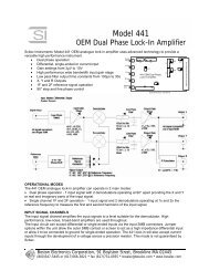
FEMTO-SECOND LASER PULSE ACQUISITION SYSTEM<br />
Φ<br />
Φ<br />
Φ<br />
Φ<br />
Φ<br />
Φ<br />
Φ<br />
High-Speed Box Car Integrator System for MCT Arrays<br />
16 to 256 Channels Simultaneously Acquired<br />
Femtosecond to Microsecond Pulse Durations<br />
1.9Khz Maximum Repetition Rate with No Lost Data<br />
Very Low Noise 16 Bit Data Acquisition<br />
Complete Detector Array Interface, Data Acquisition and Storage<br />
Labview Software Controlled with 10 Mhz Data Rate<br />
The New Femto-Second Laser Pulse Acquisition System (FPAS) was developed for high speed laser<br />
“Pump-Probe” spectroscopy providing simultaneous sampling of Multi-Element HgCdTe (MCT) Detector<br />
Arrays. The FPAS integrates and captures detector signals from short pulse, high-energy laser <strong>systems</strong><br />
with excellent linearity and a true 16-Bit resolution.<br />
The FPAS provides all of the system components required to acquire Femto-Second spectroscopy data,<br />
including user inputs to monitor chopper phase, stepper motor positions, single detectors, and any other<br />
user data needed to be acquired with the Array data. The system includes Preamplifiers, Integrators,<br />
Sample & Holds, Multiplexers, 16-Bit A/D Converters, FIFO Memory, Digital I/O PCI Card and Host<br />
Computer System with custom LABVIEW Software for complete control and data presentation. Labview<br />
source code is included to allow the user to integrate other functions and controls within one software<br />
application.<br />
The acquisition starts with the rising edge of the Laser sync pulse, which initiates the delay time. The<br />
signal appears at the MCT Array 50-500 ns after the laser fires. The Integration Gate then acquires the<br />
preamplifier output signal and Holds until the ADC can digitize and store the data. A user selectable<br />
number of laser shots, up to 1 million shots can be acquired in a single operation.<br />
The MCT detector can be configured as a single row or as two rows. The single row configuration<br />
acquires data that can be chopped or monitored to compensate for amplitude variations from shot to<br />
shot of the laser. The dual row configuration allows compensation for amplitude variations and<br />
wavelength variations to cancel the unstable effects of the laser.<br />
Versatility is required in many 2D Vibrational Spectroscopy measurements and the FPAS system allows<br />
the user to take measurements in many experimental configurations. Our customer support team has<br />
experience with many techniques and is ready to assist with hardware and software support and<br />
modifications to suit your needs.<br />
4
Specifications:<br />
Laser Pulse Repetition Rate: 0 to 1.9 Khz<br />
Integration Time: Adjustable in 10 ns steps between 54 to 2600 ns.<br />
Integration Delay: Adjustable in 2 ns steps between 30 to 520 ns. Other<br />
ranges are available<br />
Integrator Type: Boxcar type, Low noise, current steering, auto-reset,<br />
integrator section. Simultaneous acquisition of 16 to<br />
256 channels. Using multiple units in parallel<br />
provides more than 1024 channels.<br />
Detector Interface<br />
Photoconductive: HgCdTe (MCT)-Low Noise Amplifier with Bias<br />
Photovoltaic: InSb- Low Noise FET Amplifier with Zero Volt Bias<br />
HgCdTe (PVMCT)- Low Noise Amplifier with Zero<br />
Volt Bias.<br />
A/D Conversion: 16 Bit, + 10V to –10V input Multiplexed 16 channels<br />
per A/D converter<br />
Maximum Number of 1 Million complete scans of all channels<br />
Samples:<br />
FIFO Memory: 1024 x 16 FIFO Memory<br />
Data Communications: FIFO Memory is read out by a 10 MHz digital<br />
communications port. Requires PC Plug-in Card<br />
Signal: Approximately 7 Volts from 80 femtosecond laser at<br />
7 um<br />
EQV Noise: Less than 1.5 nv/Hz 1/2 at input<br />
System Signal to Noise: >>80 db(10,000:1) at 1000 scans<br />
Digital Noise: +/- ½ LSB<br />
Typical System Noise: +/- 2 LSB rms (1000 Scans @ 2Khz Laser Rep Rate)<br />
Digital Dynamic Range: -32767 to + 32767 = 65535 (16 Bits)<br />
Analog Dynamic Range: -10 V to +10V<br />
Model Array Size External<br />
Inputs<br />
IR-3216 32 16<br />
IR-6400 64 0<br />
IR-6416 64 16<br />
IR-0128 128 0<br />
IR-0144 128 16<br />
FPAS<br />
5
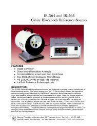
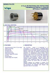
SPECTRALMASTER MARK III RADIOMETER<br />
FIELD RESEARCH RADIOMETER<br />
UNMATCHED PERFORMANCE<br />
FIELD PROVEN RELIABILITY<br />
Outstanding Features:<br />
Typical Applications:<br />
Φ Unmatched sensitivity and reliability Φ Emission Signatures<br />
Φ Field-proven rugged optical system Φ Countermeasures<br />
Φ New slim profile electroics/processor Φ Transfer Calibration<br />
Φ Upgrade for IRSI or Barnes Mark II Φ Transmissometry<br />
System<br />
Φ Transient Phenomena<br />
Φ Spectral scanning modules and fore Φ Laser Target Diagnostics<br />
optics options<br />
Φ Combustion and Flame Front<br />
Φ Works with any PC Serial Port Analysis<br />
Φ Faster menu-driven processing with<br />
pop up menus<br />
The ISDC SpectralMaster Mark III combines proven field ruggedness, new lightweight portability,<br />
unmatched sensitivity and the fastest, most advanced data acquisition and processing available<br />
in <strong>systems</strong> of its type. The standard system includes the Mark III Radiometer, Laptop Computer<br />
and Compurad 5 Windows Software. In addition to commanding the mission, the computer now<br />
performs all of the calculations that were previously the painstaking responsibility of the user.<br />
The electronics/data processing package allows the entire measurement mission to be controlled<br />
by means of the computer. The disk storage capacity provides space for storing considerable<br />
real time measurement data as well as all of the throughput characteristics (transfer functions)<br />
necessary to convert raw measurements to quantitative radiometric data. The operator needs to<br />
have only a rudimentary knowledge of the calculations involved. Human error is virtually<br />
eliminated and system field calibration is reduced to a few simple steps.<br />
Unmatched Sensitivity and Reliability<br />
The patented signal processing method introduced by the Mark III System results in<br />
approximately an order of magnitude testable improvement in measurement sensitivity over<br />
previous and competitive <strong>systems</strong>. Example: NET (noise equivalent temperature), the traditional<br />
figure of merit yardstick by which radiometric <strong>systems</strong> are compared, has been constantly<br />
measured to be 0.0003º C (RMS, Bandwidth = 1 Hz, Target temperature at 25º C, CVF open)<br />
using our standard 4.25” high-resolution Cassegrain fore optics. What this means in practice is<br />
that you can expect better than four times the performance using our standard optics than you<br />
can obtain with 6” optics on other commercial <strong>systems</strong>.<br />
6
Field Proven Rugged Optical System<br />
The original Barnes-designed rigid optical bench construction of the radiometer head has been<br />
retained and improved as ease of field interchangeability of operating modules has been emphasized.<br />
A history of 25 years in the field supports your confidence in the stability of your sensor unit.<br />
New Slim Profile <strong>Electronics</strong>/Processor<br />
Our new approach to signal processing has resulted in a most welcome reduction in size, weight and<br />
complexity of the electronics/processor unit. The new unit is one-fifth the volume and one-half the<br />
weight of the Mark II and most competitive units. It mounts directly below the sensing head, and the<br />
total combined weight is less than 40 lbs. To the user, the reduced complexity of the new processor (3<br />
processing boards replace 14 on the Mark II) also means drastically reduced parts count for higher<br />
reliability. The new processor also has twice the RAM (random access memory) capacity of previous<br />
models.<br />
Upgrade for Barnes Mark II System<br />
The SpectralMaster Mark III electronics/processor can be retrofitted easily and economically to<br />
operate with any Barnes Mark II System sensing head with no changes to the sensing head. This<br />
extremely cost-effective retrofit will preserve the versatility of your present system with all of its<br />
interchangeable modules. Your gains will be in greatly improved sensitivity, field portability and<br />
reliability.<br />
Fully Field-Interchangeable Detector Modules<br />
The Mark III sensing head accepts a broad selection of fully field-interchangeable detector preamplifier<br />
assemblies featuring the liquid nitrogen cooled InSb/HgCdTe “sandwich” detector, Si/PbS, Si/PbSe,<br />
InSb and Pyroelectric detectors.<br />
Spectral Scanning Modules and Fore Optics Options<br />
A variety of spectral scanning modules featuring discrete filters and CVF elements are available, as on<br />
previous models, all easily field-interchangeable. The SpectralMaster Mark III comes with high<br />
resolution 4.25 inch Cassegrain fore optics. Standard fields of view are 2.5 milliradian, 0.5 degree and<br />
1 degree, with optional 1 milliradian field of view available. Wide field attachments for 3, 10 and 20<br />
degrees are available with all standard fields of view. Other special fore optics and attachments are<br />
available.<br />
Works with any Computer<br />
The SpectralMaster Mark III system package includes a Laptop Computer. However, it will operate<br />
with any computer with Windows 2000, XP.<br />
MARK III<br />
7
MARK III<br />
Faster Menu-driven Processing with Pop-Up Menus<br />
The new COMPURAD 5 software comes installed in the computer. The software features popup<br />
menus and sub-menus that appear on the display to guide you through the processing<br />
routines. Some of the processing capabilities under keyboard control are:<br />
Command the CVF (one position, increment, full scan or multiple scans), chop speed (0-1000<br />
Hz), reference cavity temperature (0-55°C) and system gain (1-1000).<br />
Save incoming raw data to your disk or diskette and/or Hold in RAM data matrix arrays (21 data<br />
arrays in random access memory).<br />
Autocompute radiance or irradiance for full-field and point-source targets.<br />
Plot raw data, radiance or irradiance vs. wavelength, or data at any wavelength vs. time.<br />
Plot raw data vs. wavelength in near real-time.<br />
Save all data to disk or diskette for immediate recall.<br />
Printout or Plot all data displayed on the color monitor.<br />
Create and Plot a blackbody curve for any temperature increment in the radiance curve.<br />
Display multiple plots including blackbodies with autoscale, manual scaling or log scaling.<br />
Compare (autosubtract) any two scans and tabulate, plot or save the “delta” to disk or diskette.<br />
Zoom on graphics to magnify any spectral interval.<br />
RADIOMETER<br />
OPTICAL SYSTEM<br />
8
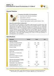
PRS-2000<br />
DUAL CHANNEL PYROELECTRIC<br />
RADIOMETER SYSTEM<br />
IR INTENSITY TEST SYSTEM<br />
The PRS-2000 Dual Pyro-Radiometer Measures Energy in Two Spectral bands<br />
simultaneously. Its applications include Counter-Measure Flare Analysis, and Radiant<br />
Intensity Measurements. Custom Radiant Intensity Profile Software is Included.<br />
MAIN SELECTION SCREEN DATA ACQUISITION SCREEN CALIBRATION SETUP<br />
SCREEN<br />
PRS-2000<br />
9
IR-704/301<br />
MULTI-SPECTRAL<br />
IR TARGET SYSTEM<br />
The IR-704 system integrates a Blackbody source, Motorized Aperture wheel,<br />
Motorized Filter Wheel, High Speed Shutter and High Speed Filter Shutter. The system<br />
was designed as a forced air-cooled Multi-Spectral, Multi-Aperture target system for<br />
direct integration with collimator / target projection <strong>systems</strong>, but can also be used as a<br />
direct target system. System operations are controlled by an internal microprocessor<br />
with RS-232 / RS-485 control interface, or an auxiliary direct hardware port.<br />
The system is optically arranged with a ¼” Cavity Blackbody source, 4 position aperture<br />
wheel, 4 position filter wheel, filter solenoid and shutter solenoid. Each of the assets are<br />
individually controlled via Serial port commands to allow Blackbody temperature control,<br />
Aperture selection, Filter selection, Shutter solenoid activation and Filter solenoid<br />
activation. The activation time of the shutter and filter solenoids is less than 5<br />
milliseconds to allow target high-speed progression from Off to Dual filtered to filtered in<br />
less than 10 milliseconds.<br />
The individual control ability of each of the IR-704’s <strong>systems</strong> allows for 32 different<br />
combinations of Filter / Aperture / Shutter selections coupled with a variable<br />
temperature blackbody source, from 50°C to 1050°C provide virtually limitless variability<br />
in Infrared energy output levels.<br />
Temperature Range: 50-1050C<br />
Emitter Size: 0.25” Cavity<br />
Stability Short / Long: 0.1C +/- 0.2C<br />
Fixtures / Apertures: 14 Positions on 2 Wheels<br />
Shutter Response:
FRONT VIEW<br />
WITH FRONT PLATE REMOVED<br />
SIDE VIEW<br />
IR-704/301<br />
11
APPLICATIONS<br />
At Infrared Systems Development, we<br />
offer a wide variety of Infrared Test<br />
Equipment. We have many standard<br />
products as well as design services to<br />
produce products to fit your application.<br />
1” CAVITY BLACKBODY (IR-563/IR-564)<br />
SYSTEM WITH INTELLIGENT FILTER WHEEL,<br />
INSB-1000 PREAMPLIFIER, DETECTOR AND<br />
X-Y TRANSLATION TABLE<br />
TESTING IR-6416 FEMTOSECOND DATA<br />
ACQUISITION SYSTEM WITH SPECTROMETER<br />
LASER DIODE, AND X-Y-Z TRANSLATION TABLE<br />
IR-2106 BLACKBODY SYSTEM WITH 640X480 IR CAMERA<br />
12
Φ CAVITY BLACKBODY SYSTEMS<br />
The Cavity Blackbody Systems are an ideal source for the Near (1-3 um), Mid<br />
(3-8) and Far (8-30+ um) <strong>infrared</strong> bands. They are designed to provide <strong>infrared</strong><br />
radiation as an ideal blackbody emitter. The output energy from the cavity<br />
closely follows the theoretical maximum energy curve described by Max<br />
Planck’s equation, and allows users to calibrate, align, and measure <strong>infrared</strong><br />
devices and phenomena of all types.<br />
The 20º tapered - recessed - cone, surface emissivity, and cavity aspect ratio<br />
combine to provide blackbody radiation by multiple reflection, absorption and<br />
re-emission of its thermal energy. The thermal energy of the cavity is provided<br />
by a ceramic-sealed heater coil that uniformly heats the cavity cylinder.<br />
The IR-563 and IR-508 system carry a full, two-year warranty due to the<br />
reliability of actual field units used over the last 30 years.<br />
IR-508/301: The smaller size and lower power consumption make the IR-508<br />
ideal for applications with limited space and power, such as in environmental<br />
chambers down to -80º C. Using the optional 8 position aperture wheel, the<br />
<strong>infrared</strong> flux can be varied by known amounts without disturbing critical optical<br />
setups, and combining apertures and distance changes, the flux at any point<br />
can easily be determined.<br />
The IR-563 has been the industry standard 1000ºC blackbody for more than 30<br />
years, and continues to provide excellent service to <strong>infrared</strong> applications<br />
throughout the industry. The IR-564 extends the temperature range of the IR-<br />
563 to 1200 º C by changing cavity materials to Silicon Carbide and high purity<br />
Alumina ceramics; otherwise the two units are virtually identical.<br />
Using an aperture wheel, which comes standard on the IR-563 and IR-564, the<br />
<strong>infrared</strong> flux can be varied by known amounts without disturbing critical optical<br />
setups, and combining apertures and distance changes, the flux at any point<br />
can easily be determined.<br />
7319 SANDSCOVE CT. #4 Φ WINTER PARK, FL 32792<br />
(TEL) 407-679-5101 Φ (FAX) 407-679-5520<br />
SALES@INFRAREDSYSTEMS.COM HTTP://WWW.INFRAREDSYSTEMS.COM 13
Φ CAVITY BLACKBODY SYSTEMS<br />
MODEL TEMPERATURE CAVITY<br />
OPENING<br />
PAGE<br />
IR-508/301 50-1050ºC 0.25” 15<br />
IR-518/301 50-1050ºC 0.40” 16<br />
IR-563/301 50-1050ºC 1” 17<br />
IR-564/301 50-1200ºC 1” 17<br />
IR-574/301 50-1200ºC 2.25” 18<br />
IR-301 CONTROLLER<br />
PAGE 26<br />
14
IR-508/301<br />
Specifications:<br />
Temperature Range: 50 to 1050ºC<br />
Emittance Watts/Cm^2 (Watts): 17.36 (5.5)<br />
Wavelength Range: 0.5 - 99um<br />
Emissivity: >0.99<br />
Emitter Size: in (mm) 0.25" (6.3)<br />
Source Type: Cavity<br />
Temperature Resolution: 0.1ºC<br />
Calibration Accuracy: +/- 0.2ºC to NIST Standard<br />
Stability: Short (Long) Term: +/- 0.1ºC (+/- 0.2ºC)<br />
Response Time: 100-1000
IR-518/301<br />
CAVITY BLACKBODY<br />
Specifications:<br />
Temperature Range: 50 to 1050ºC<br />
Emittance Watts/Cm^2 (Watts): 17.36 (14)<br />
Wavelength Range: 0.5 - 99um<br />
Emissivity: >0.99<br />
Emitter Size: in (mm) 0.4" (10)<br />
Source Type: Cavity<br />
Temperature Resolution: 0.1ºC<br />
Calibration Accuracy: +/- 0.2ºC to NIST Standard<br />
Stability: Short (Long) Term: +/- 0.1ºC (+/- 0.2ºC)<br />
Response Time: 100-1000
IR-563 & IR-564<br />
Specifications:<br />
Temperature Range: IR-563: 50 to 1050º C<br />
IR-564: 50 to 1200º C<br />
Emittance Watts/Cm^2 (Watts): IR-563: 17.36 (88)<br />
IR-564: 26.68 (135)<br />
Wavelength Range: 0.5 - 99um<br />
Emissivity: >0.99<br />
Emitter Size: in (mm) 1" (25.4)<br />
Source Type: Cavity<br />
Temperature Resolution: 0.1 C<br />
Calibration Accuracy: +/- 0.2 C to NIST Standard<br />
Stability: Short (Long) Term: +/- 0.1 C (+/- 0.2C)<br />
Response Time: IR-563: 100-1000
IR-574/301<br />
CAVITY BLACKBODY<br />
Specifications:<br />
Temperature Range: 50 to 1200º C<br />
Emittance Watts/Cm^2 (Watts): 26.68 (684)<br />
Wavelength Range: 0.5 - 99um<br />
Emissivity: >0.99<br />
Emitter Size: in (mm) 2.25" (57)<br />
Source Type: Cavity<br />
Temperature Resolution: 0.1 C<br />
Calibration Accuracy: +/- 0.2 C to NIST Standard<br />
Stability: Short (Long) Term: +/- 0.1 C (+/- 0.2C)<br />
Response Time: 100-1200
Φ EXTENDED AREA BLACKBODY SYSTEMS<br />
Our extended area sources are flat<br />
plate emitters with special high<br />
emissivity coating providing 0.96<br />
average emissivity. Extended area<br />
sources provide large target with high<br />
radiant intensity for application where a<br />
cavity blackbody is too small.<br />
The NEW Low-Cost Thermo-Electrically<br />
cooled / Heated blackbody sources with a<br />
solid Copper Emitter plate provides superior<br />
uniformity and energy emission. Our<br />
Proprietary High Emissivity Black Coating<br />
provides >0.95 uniform Emissivity from 0.8 to<br />
30 um. A Type "T" Thermocouple is<br />
embedded in the emitter plate to allow<br />
independent monitoring and calibration of the<br />
surface temperature. The IR-2100 series<br />
offers stability and uniformity comparable to<br />
competitive <strong>systems</strong> costing more than<br />
$20,000 for a fraction of their costs, providing<br />
the best cost to performance ratio.<br />
19
EXTENDED AREA BLACKBODY SYSTEMS<br />
MODEL TEMPERATURE CAVITY<br />
OPENING<br />
PAGE<br />
IR-2100 -5 to 145ºC 2.5” x 2.5” 21<br />
IR-2101 -30 to 75ºC 2.5” x 2.5” 21<br />
IR-2103 -5 to 145ºC 3” x 3” 22<br />
IR-2106 5 to 150ºC 6” x 6” 23<br />
IR-140 AMBIENT TO 230ºC 12” x 12” 24<br />
IR-160 AMBIENT TO 350ºC 12” x 12” 24<br />
IR-150 AMBIENT TO 500ºC 12” x 12” 24<br />
IR-301 CONTROLLER<br />
PAGE 26<br />
20<br />
7319 SANDSCOVE CT. #4 Φ WINTER PARK, FL 32792<br />
(TEL) 407-679-5101 Φ (FAX) 407-679-5520<br />
SALES@INFRAREDSYSTEMS.COM HTTP://WWW.INFRAREDSYSTEMS.COM
IR-2100/301<br />
Specifications:<br />
Temperature Range: IR-2100: -5 to 145 C<br />
IR-2101: -30 to 75ºC<br />
Emittance Watts/Cm^2 (Watts): .17 (5.4)<br />
Wavelength Range: 1-99 um<br />
Emissivity: 0.96 +/- 0.02<br />
Emitter Size: in (mm) 2.5” x 2.5” (63.5 x 63.5)<br />
Source Type: Extended Area<br />
Temperature Resolution: 0.1 C<br />
Calibration Accuracy: +/- 0.2 C to NIST Standard<br />
Stability: Short (Long) Term: +/- 0.1 C (+/- 0.2C)<br />
Response Time: Ambient – Max
IR-2103/301<br />
EXTENDED AREA<br />
BLACKBODY<br />
Specifications:<br />
Temperature Range: -5 to 145 ºC<br />
Emittance Watts/Cm^2 (Watts): .17 (7.75)<br />
Wavelength Range: 1-99 um<br />
Emissivity: 0.96 +/- 0.02<br />
Emitter Size: in (mm) 3” x 3” (76.2 x 76.2)<br />
Source Type: Extended Area<br />
Temperature Resolution: 0.1 C<br />
Calibration Accuracy: +/- 0.2 C to NIST Standard<br />
Stability: Short (Long) Term: +/- 0.1 C (+/- 0.2C)<br />
Response Time: Ambient – Max
IR-2106/301<br />
Specifications:<br />
Temperature Range: 5 to 150º C<br />
Emittance Watts/Cm^2 (Watts): 0.17 (5.4)<br />
Wavelength Range: 1-99 um<br />
Emissivity: 0.96 +/- 0.02<br />
Emitter Size: in (mm) 6” x 6” (152.4 x 152.4)<br />
Source Type: Extended Area<br />
Temperature Resolution: 0.1 C<br />
Calibration Accuracy: +/- 0.2 C to NIST Standard<br />
Stability: Short (Long) Term: +/- 0.1 C (+/- 0.2C)<br />
Response Time: Ambient – Max
IR-140, 150, 160<br />
Specifications:<br />
Temperature Range:<br />
IR-140: Amb to 230º C<br />
IR-160: Amb to 350º C<br />
IR-150: Amb to 500º C<br />
Emittance Watts/Cm^2 (Watts): IR-140: 0.36 (334)<br />
IR-160: 0.85 (789)<br />
IR-150: 2.02 (1876)<br />
Wavelength Range:<br />
1 - 99um<br />
Emissivity: 0.96 +/- 0.02<br />
Emitter Size: in (mm) 12” x 12” (304 x 304)<br />
Source Type:<br />
Extended Area<br />
Temperature Resolution: 0.1C<br />
Calibration Accuracy:<br />
+/- 0.2 C to NIST Standard<br />
Stability: Short (Long) Term: +/- 0.1 C (+/- 0.2C)<br />
Response Time:<br />
Ambient – Max < 50 Minutes<br />
Temperature Sensors:<br />
IR-140: Platinum RTD & Type T<br />
IR-160: Platinum RTD & Type T<br />
IR-150: Platinum RTD & Type S<br />
Control Type:<br />
Active Multi-Band P.I.D.<br />
Line Voltage:<br />
IR-140: 90-125 or 208-240 VAC 50-60 Hz<br />
IR-160: 90-125 or 208-240 VAC 50-60 Hz<br />
IR-150: 208-240 VAC 50-60 Hz<br />
Power Requirements:<br />
IR-140: 1500 Watts Max<br />
IR-160: 2000 Watts Max<br />
IR-150: 4500 Watts Max<br />
Cable Length: 8 Feet (2.4 m)<br />
Dimensions: in (mm) Source: 17” H x 17” D x 17” W (432x432x432)<br />
Controller:<br />
5.1"H x 13.4"D x 12"W (130x340x304)<br />
Warranty:<br />
1 Year<br />
Standard Apertures:<br />
12” x 12” (304 x 304 mm)<br />
Remote Interface:<br />
RS-232, RS-485 or IEEE-488/GPIB<br />
24
DIMENSIONS<br />
IR-140, 150, 160 25
IR-301<br />
BLACKBODY SOURCE<br />
CONTROLLER<br />
Temperature Range: 50ºc to 1200ºC Sample Rate: Cavity Temp is updated 10 times per<br />
second; digitally filtered to eliminate noise<br />
Calibration<br />
+/- 0.2ºC +/- 1 digit ºF/ºC Selected at Factory<br />
Accuracy:<br />
Stability: +/- 0.02% of full scale Alarms: 5.0 amps at 120 VAC, 2.5 amps at 230<br />
VAC<br />
Resolution: 1ºC or 0.1ºC Selectable Operating<br />
Environment:<br />
0 to 40ºC ambient temp with relative<br />
humidity less than 95% non-condensing<br />
Warm-Up Time: 35 Minutes Power 105-125 Volts, 50-60 Hz., 500 Watts Max<br />
Requirement:<br />
Control:<br />
PID dual Zero voltage firing<br />
state power relays<br />
Dimensions<br />
(HxWxL):<br />
5.10” x 12” x 13.4”<br />
(Rackmounted 5.25” x 19” x 14.4”<br />
Readout:<br />
Dual display: BB Temp is<br />
shown on upper LED display;<br />
Set Point and Parameters are<br />
shown on lower LCD Display<br />
Weight: 9 lbs. (Rackmounted 10bs.)<br />
(Shipping Weight: 13 lbs. 17lbs.)<br />
The IR-301 controller is a microprocessor based PID (Proportional, Integral and Derivative) system for<br />
regulating the Blackbody's Radiating Surface. At Infrared Systems Development, we have taken a leap<br />
forward from the standard PID Controller types of past years. We do this by utilizing five (5) independent<br />
PID parameter groups, each for a specific temperature range, internally selected based on the Setpoint.<br />
To control stability, the Standard Proportional Band with Automatic Reset and Derivative method is<br />
utilized. Unlike standard PID control, these parameters are totally dedicated to control stability only. This<br />
allows us to reduce the Proportional Band, creating a much more stable Blackbody system.<br />
To control warm-up characteristics, we start with an independent Proportional Band, much wider than the<br />
stability Proportional Band. We then take the operational span and divide it into five smaller spans. Each<br />
of these spans is assigned a factory-selected range of PID Parameters values. Selecting a set<br />
temperature automatically loads the proper warm-up parameters into memory for that specific<br />
temperature. This process practically eliminates the need for continuous reactionary parameter changes<br />
as required by standard PID.<br />
All control parameters, selections, and calibration procedures are accomplished through simple MENU<br />
selections using the four front panel buttons. These MENU selections are organized into Sections. Each<br />
Section presents a specific set of related functions. Internally the IR-301 was designed for maximum<br />
accuracy while maintaining our trademark reliability and quality. As is apparent with the use of dual<br />
redundant solid state (zero-voltage switching) power relays, RFI filters and an entire temperature sensor<br />
feedback loop; wire, cable, pins and connectors, being manufactured from special thermocouple alloys to<br />
eliminate the effects of ambient temperature change. The Thermocouple Cold Junction is mounted to a<br />
high precision RTD sensor to accurately monitor the CJC to provide compensation for ambient<br />
temperature variations. All connections are made from the rear for true Rackmount capabilities.<br />
26
DIMENSIONS<br />
IR-301 WITH RACKMOUNT<br />
ACCESSORY<br />
IR-301<br />
27
ENERGY MODULATOR SYSTEMS<br />
IR-860<br />
Modulator for<br />
IR-563<br />
IR-564<br />
Page 42<br />
IR-762<br />
Modulator for<br />
IR-508<br />
IR-518<br />
Page 43<br />
The Energy Modulator is a variable speed rotating disk chopper designed for use with<br />
radiation sources, including blackbody, tungsten filament, mercury lamps Nernst glowers<br />
and as part of instruments where modulated radiation is needed.<br />
The IR-860 has been specially designed to integrate with the IR-563 & IR-564<br />
Blackbody Sources while the IR-762 is designed for the IR-508 and IR-518 blackbody<br />
Sources. For other applications a table mount is available. The System consists of the<br />
Modulator head assembly and Modulator controller. The controller operates the motor<br />
and blade rotation and controls the speed of the modulation frequency.<br />
The Modulator unit of the IR-860 contains an interchangeable chopper blade attached to<br />
a hub of a Brushless DC Motor. This motor allows the blade to stop at an open position<br />
by depressing the HOLD switch or shorting the remote hold BNC. The blade is attached<br />
to the motor shaft and rotated to align the hold position of the motor with an open<br />
position of the blade.<br />
Three sensors detect the rotor motion in the motor and feedback the signal to the drive<br />
circuitry to ensure accurate closed loop speed control. A BLDC motor controller is used<br />
to provide the motor drive and sensor signal processing. A built in phase reference<br />
pickup, or optical sensor is provided to allow the user to measure and monitor the actual<br />
chopping frequency through the front panel meter or the rear panel Freq Out BNC. This<br />
signal is a TTL 0-5V square wave.<br />
28<br />
7319 SANDSCOVE CT. #4 Φ WINTER PARK, FL 32792<br />
(TEL) 407-679-5101 Φ (FAX) 407-679-5520<br />
SALES@INFRAREDSYSTEMS.COM HTTP://WWW.INFRAREDSYSTEMS.COM
ENERGY MODULATOR<br />
SYSTEMS<br />
Specifications:<br />
Motor Spindle Speed<br />
Range:<br />
Warm Up Time:<br />
BLADE TYPES:<br />
Blade<br />
Stability:<br />
Control Type:<br />
Meter Indication:<br />
Meter Accuracy:<br />
Reference Frequency<br />
Output:<br />
Power Requirements:<br />
Dimensions:<br />
Modulator:<br />
Controller:<br />
Freq Range<br />
IR-860<br />
Weight:<br />
75-7500 RPM<br />
1 Hour for Optimum Stability<br />
0.5% of set frequency or 0.25% of<br />
full scale over 4 hours<br />
Closed Loop Brushless DC Motor<br />
Controller with Phase Sensors<br />
Chopping Frequency in Hertz<br />
± 1 Digit<br />
0-5 V TTL Level, 600 Ohms Output<br />
200 Watts 110 or 220 VAC<br />
50-60 Hz<br />
6.88” Diameter (175mm)<br />
8.5” x 8” x 3.75” (216x203x95mm)<br />
6.5 lbs<br />
Number<br />
of Slots<br />
Slot Width<br />
@ Center<br />
A 1.25-125HZ 1 7.854” 1.0”<br />
B 2.5-250HZ 2 3.927 1.0<br />
Maximum<br />
Aperture<br />
STANDARD BLADE<br />
C 10-1000HZ 8 0.982 0.992<br />
D 30-3000HZ 24 0.327 0.327<br />
E 50-5000HZ 40 0.196 0.196<br />
F 100-10000HZ 80 0.098 0.098<br />
G 300-30000HZ 240 0.0327 0.0327<br />
H 62.5-6250HZ 50 0.157 0.157<br />
J 450-45000HZ 360 0.022 0.022<br />
K 3.75-375HZ 3 2.618 1.0<br />
Specifications:<br />
Dimensions: 5.8”W x 2.8”H x 12.5”D<br />
Input and Output BNC’s<br />
Connectors:<br />
Frequency Control: Up/Down Keypad Switches<br />
Mode Control: Keypad Switch Enable with LED<br />
Illuminated Selection<br />
External Control: Keypad Switch Enable with LED<br />
Indication<br />
Input Power<br />
Connection:<br />
IEC Connector with US style<br />
power cord<br />
Weight: 5lbs (10 lbs. Shipped weight)<br />
Operating Temp: 10-40º C<br />
Display Type: Green LED Segments<br />
No of Digits: 4<br />
Frequency Resolution: 1 HZ<br />
762 HEAD<br />
Motor: 11 pole dc motor, sleeve bearing,<br />
precious metal brushes<br />
Ambient Temp: -20ºC to + 65ºC<br />
Optical Sensor: High speed, IR LED<br />
Phototransistor Switch<br />
POWER SUPPLY<br />
Supply Type: Linear<br />
Voltage Selection: 115 / 230 VAC<br />
Input Voltage: 110 / 115 VAC +/- 10%, 230VAC<br />
+/- 10%<br />
Line Frequency: 50-60Hz<br />
Input Power: 20VA MAX<br />
Fuse Ratings: 250mA @ 115VAC<br />
125mA @ 230VAC<br />
Fuse Type: IEC60127-2/III (250V, Slow Blow<br />
Type ‘T’<br />
BLADE TYPES:<br />
Freq Range<br />
IR-762<br />
Number<br />
of Slots<br />
Maximum<br />
Aperture<br />
Jitter<br />
20-200HZ 2 1.85” +/- 0.2º max<br />
STANDARD BLADE<br />
20Hz-1KHZ 10 0.40” +/- 1º max<br />
60JZ-3KHZ 30 0.13” +/- 3ºmax<br />
29
INTELLIGENT FILTER WHEEL<br />
Φ<br />
Φ<br />
Φ<br />
Φ<br />
Remote Motorized Wheel<br />
5 or 8 Position Wheel<br />
Filters or Apertures<br />
PC Controllable via RS-232<br />
The IFW has the ability to determine the identification (ID) of a particular wheel and apply that wheel<br />
ID to a preprogrammed set of filters or apertures. The names, not just position numbers of these<br />
filters, are displayed on the eight character display and are also available to the operating software<br />
via an RS-232 interface using a simple command structure. Up to 5 different filter wheels can have<br />
separate IDs and each wheel can have up to 5 filters for a total of 25 identifiable filters.<br />
The IFW filter wheel can easily be removed from the IFW system without tools or removal from the<br />
equipment. A hinged door is secured by a single captive thumbscrew. Once opened, the wheel can<br />
be extracted and another inserted in its place. The entire process takes only a few seconds. Hitting<br />
the HOME switch on the hand control or invoking the HOME function in the operating program will set<br />
the wheel to position one and bring up the available filters for that wheel.<br />
The IFW can be controlled by either the switches on the hand control, an SBIG camera controller, or<br />
by an external computer via an RS-232 interface. The RS-232 operating protocol is a set of simple<br />
ASCII commands that any programmer can easily implement. While any software capable of<br />
controlling the SBIG CFW-8 filter wheel can immediately control the IFW, we believe developers will<br />
incorporate the IFW serial operating protocol since it offers full feedback including filter names. The<br />
IFW control software can be used for the filter description programming and also for filter selection<br />
and control.<br />
A control cable with 8-pin modular connector on one end and a 9-pin sub-D connector on the other is<br />
used to connect the IFW to the hand control box. Lengths of cable 6, 12, 25 and 50 feet as well as<br />
custom lengths are available. This is the same cable used with the TCF focuser and can be<br />
interchanged.<br />
30<br />
7319 SANDSCOVE CT. #4 Φ WINTER PARK, FL 32792<br />
(TEL) 407-679-5101 Φ (FAX) 407-679-5520<br />
SALES@INFRAREDSYSTEMS.COM HTTP://WWW.INFRAREDSYSTEMS.COM
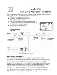
PREAMPLIFIERS<br />
SINGLE ELEMENT<br />
Infrared Systems Development produce preamplifiers, which provide complete<br />
detector interfacing. The proper bias voltage and input stage are selected for<br />
each detector type. The preamplifier output is suitable for driving test<br />
equipment, A/D cards and instrument circuitry. We fully test and integrate the<br />
detector with the preamplifier when supplied, or simulated detector<br />
components. Each amplifier is tested with methods most closely matching the<br />
final application. From DC response to femtosecond laser pulse, our preamps<br />
are optimized to provide the best performance for each task.<br />
MODEL Type Bandwidth Gain<br />
MCT-1000 PC HgCdTe 1.5Hz – 150kHz 50-1000<br />
MCT-1000DC PC HgCdTe DC – 150kHz 50-1000<br />
MCT-1000H PC HgCdTe 1.5Hz – 150kHz 200-4000<br />
MCT-1000HS PC HgCdTe 500Hz – 1.0MHz 50-1000<br />
PVMCT-1000 PV HgCdTe 1.5Hz – 150kHz 5-100<br />
MCT Array PC or PV HgCdTe Any DC-1.0Mhz 5-1000<br />
INSB-1000 PV InSb 1.5Hz – 200kHz 5-100<br />
INSB-1000DC PV InSb DC – 200kHz 5-100<br />
INSB-1000HS PV InSb 2mm 500HZ – 1.0MHz 0.5-10<br />
INSB-1000HS PV InSb 1mm 500Hz – 1.0MHz 2.5-30<br />
PYRO-1000 DTGS and LiTaO3 1.5Hz – 10kHz 50-1000<br />
PB-1000 PbS/PbSe 1.5Hz – 50kHz 2-200<br />
INGAAS-1000 InGaAs 1.5Hz – 50kHz 5-100<br />
VA-1000 Any 10Hz – 500Hz 100-3000<br />
Bias Adjust<br />
Access Port<br />
Zero Adjust<br />
Access Port<br />
Zero Adjust<br />
Test Point<br />
MCT<br />
Detector<br />
Input<br />
InSb<br />
Detector<br />
Input<br />
Φ<br />
ZERO<br />
30 – 80 Ω<br />
1.5-150KHz<br />
MCT<br />
GND<br />
TP1<br />
BIAS<br />
I N F R A R E D S Y S T E M S D E V E L O P M E N T<br />
CORPORATION<br />
-15V<br />
IN<br />
BIAS<br />
IN<br />
GAIN<br />
OUT<br />
ZERO<br />
M CT-1000<br />
Current Mode<br />
Preamplifier<br />
GAIN<br />
OUT<br />
+15V<br />
Φ<br />
IN INSB-<br />
1000<br />
Current Mode<br />
INFRARED SYSTEMS DEVELOPMENT<br />
Preamplifier<br />
CORPORATION<br />
InSb<br />
1.5-150KHz<br />
IN<br />
InSb<br />
GND<br />
-15V<br />
GAIN<br />
OUT<br />
OUT<br />
GAIN<br />
+15V<br />
Power<br />
Supply<br />
Ground<br />
Power<br />
Supply<br />
Ground<br />
- 15 Volts<br />
100ma<br />
Output<br />
+ 15 Volts<br />
200 ma<br />
- 15 Volts<br />
100ma<br />
Output<br />
+ 15 Volts<br />
100 ma<br />
M CT-1000 Preamplifier<br />
Figure 1<br />
Gain Adjust<br />
Access Port<br />
Gain Adjust<br />
Access Port<br />
INSB-1000 Preamplifier<br />
Figure 1<br />
31
PREAMPLIFIERS<br />
MULTI- ELEMENT<br />
ARRAY DETECTOR<br />
PREAMPLIFIERS<br />
MCT-6400<br />
Infrared Systems Development <strong>Corporation</strong> offers multi-channel preamplifiers for<br />
small and large array detectors. These preamplifiers are the same high quality low<br />
noise amplifiers as the single channel unit, packaged in multi-channel housings. Bias<br />
and Gain adjustments allow corrections for signal differences between array<br />
elements. Each element can be adjusted to compensate for responsivity variations.<br />
Bias and Responsivity (gain) of each individual array element can be tuned to<br />
provide uniform response from all elements. Front Panel input BNC connectors<br />
attach to the detector terminals and Rear Panel output BNC’s connect to signal<br />
acquisition and analysis circuitry. Low impedance output (50 Ohm) allows direct<br />
connection to PC based A/D boards, and drive long length cables. Several multichannel<br />
arrays can be used for larger arrays; two MCT-6400’s will interface with a<br />
128 Element array.<br />
PREAMP MODEL<br />
ARRAY SIZE<br />
(# OF ELEMENTS)<br />
MCT-4000 4<br />
MCT-8000 8<br />
MCT-1600 16<br />
MCT-3200 32<br />
MCT-6400 64<br />
MCT-4000<br />
32
7319 SANDSCOVE CT. #4 Φ WINTER PARK, FL 32792<br />
(TEL) 407-679-5101 Φ (FAX) 407-679-5520<br />
SALES@INFRAREDSYSTEMS.COM HTTP://WWW.INFRAREDSYSTEMS.COM
Φ<br />
INFRARED SYSTEMS DEVELOPMENT<br />
CORPORATION<br />
Infrared Systems Development <strong>Corporation</strong> (ISDC) Designs<br />
and Manufactures High Quality Electro-Optical Systems and<br />
Components for all aspects of Infrared Sciences.<br />
WE HAVE A SOLUTION FOR YOU<br />
We also develop <strong>systems</strong> for custom applications, and offer<br />
design consulting services for many <strong>infrared</strong> instrument and<br />
sub-system projects. Our experienced staff can offer<br />
assistance in almost any IR field, and offer suggestions for<br />
your system needs.<br />
Contact us for more information.<br />
Infrared Systems Development <strong>Corporation</strong><br />
7319 Sandscove Court #4<br />
Winter Park, FL 32792<br />
Phone: 407-679-5101<br />
Fax: 407-679-5520<br />
Email: sales@<strong>infrared</strong><strong>systems</strong>.com<br />
Visit us at: www.<strong>infrared</strong><strong>systems</strong>.com