Cordless System - Finn-ID
Cordless System - Finn-ID
Cordless System - Finn-ID

Create successful ePaper yourself
Turn your PDF publications into a flip-book with our unique Google optimized e-Paper software.
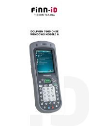
IMAGETEAM 2020/5620<br />
<strong>Cordless</strong> <strong>System</strong><br />
<br />
<strong>System</strong> Manual
Disclaimer<br />
Hand Held Products, Inc. (“Hand Held Products“) reserves the right to make<br />
changes in specifications and other information contained in this document<br />
without prior notice, and the reader should in all cases consult Hand Held<br />
Products to determine whether any such changes have been made. The<br />
information in this publication does not represent a commitment on the part of<br />
Hand Held Products.<br />
Hand Held Products shall not be liable for technical or editorial errors or<br />
omissions contained herein; nor for incidental or consequential damages<br />
resulting from the furnishing, performance, or use of this material.<br />
This document contains proprietary information which is protected by copyright.<br />
All rights are reserved. No part of this document may be photocopied,<br />
reproduced, or translated into another language without the prior written consent<br />
of Hand Held Products.<br />
© 2004-2005 Hand Held Products, Inc. All rights reserved.<br />
Web Address: www.handheld.com<br />
Microsoft Pocket PC 2002, Windows, Windows NT, Windows 2000, Windows ME,<br />
Windows XP, ActiveSync, Outlook, and the Windows logo are trademarks or registered<br />
trademarks of Microsoft Corporation.<br />
The Bluetooth® word mark and logos are owned by Bluetooth SIG, Inc.
Statement of Agency Compliance<br />
The IT2020-5B/IT5620 system meets or exceeds the requirements of all<br />
applicable standards organizations for safe operation. However, as with any<br />
electrical equipment, the best way to ensure safe operation is to operate them<br />
according to the agency guidelines that follow. Please read these guidelines<br />
carefully before using your IT2020-5B/IT5620 system.<br />
Regulatory and Safety Approvals for the IT2020-5B/<br />
IT5620<br />
Parameter<br />
USA<br />
Canada<br />
European Community<br />
Specification<br />
FCC Part 15, Class B<br />
ICES-003<br />
EN 55022 (CISPR 22) Class B<br />
EN60950<br />
EN60825-1<br />
EN55024:1998<br />
FCC Class B Compliance Statement<br />
This device complies with part 15 of the FCC Rules. Operation is subject to the<br />
following two conditions:<br />
1. This device may not cause harmful interference.<br />
2. This device must accept any interference received, including interference<br />
that may cause undesired operation.<br />
This equipment has been tested and found to comply with the limits for a Class<br />
B digital device pursuant to part 15 of the FCC Rules. These limits are designed<br />
to provide reasonable protection against harmful interference in a residential<br />
installation. This equipment generates, uses, and can radiate radio frequency<br />
energy and, if not installed and used in accordance with the instructions, may<br />
cause harmful interference to radio communications. If this equipment does<br />
cause harmful interference to radio or television reception, which can be<br />
determined by turning the equipment off and on, the user is encouraged to try to<br />
correct the interference by one or more of the following measures:<br />
• Reorient or relocate the receiving antenna.<br />
• Increase the separation between the equipment and receiver.<br />
• Connect the equipment into an outlet on a circuit different from that to which<br />
the receiver is connected.<br />
• Consult the dealer or an experienced radio or television technician for help.
If necessary, the user should consult the dealer or an experienced radio/<br />
television technician for additional suggestions. The user may find the following<br />
booklet helpful: “Something About Interference.” This is available at FCC local<br />
regional offices. Hand Held Products, Inc. is not responsible for any radio or<br />
television interference caused by unauthorized modifications of this equipment<br />
or the substitution or attachment of connecting cables and equipment other than<br />
those specified by Hand Held Products, Inc. The correction is the responsibility<br />
of the user. Use only shielded data cables with this system.<br />
In accordance with FCC 15.21, changes or modifications not expressly<br />
approved by the party responsible for compliance could void the user’s authority<br />
to operate the equipment.<br />
This device and its antenna must not be co-located or operating<br />
in conjunction with any other antenna or transmitter. To maintain<br />
! compliance with FCC RF exposure guidelines for body-worn<br />
operation, do not use accessories that contain metallic<br />
components and ensure that the device is at least 15mm (0.6<br />
inches) from the body.<br />
Canadian Compliance<br />
This Class B digital apparatus compiles with Canadian ICES-003. Operation is<br />
subject to the following two conditions:<br />
1. This device may not cause harmful interference.<br />
2. This device must accept any interference received, including interference<br />
that may cause undesired operation.<br />
3. To prevent radio interference to the licensed service, this device is intended<br />
to be operated indoors and away from windows to provide maximum<br />
shielding. Equipment (or its transmit antenna) that is installed outdoors is<br />
subject to licensing.<br />
Cet appareil numérique de la Classe B est conforme à la norme NMB-003 du<br />
Canada.<br />
CE Compliance<br />
The CE mark on the product indicates that the system has been tested<br />
to and conforms with the provisions noted within the 89/336/EEC<br />
Electromagnetic Compatibility Directive and the 73/23/EEC Low Voltage<br />
Directive.<br />
For CE-related inquiries, please contact:<br />
Hand Held Products, Inc.<br />
Nijverheidsweg 9<br />
5627 BT Eindhoven<br />
The Netherlands
Hand Held Products shall not be liable for use of our product with equipment<br />
(i.e., power supplies, personal computers, etc.) that is not CE marked and does<br />
not comply with the Low Voltage Directive.<br />
Regulatory Approvals for Bluetooth Radio Devices<br />
RF devices are designed to comply with the most current applicable standards<br />
on safe levels of RF energy developed by the Institute of Electrical and<br />
Electronics Engineers (IEEE) and the American National Standards Institute<br />
(ANSI) and have been recommended for adoption by the Federal<br />
Communications Commission (FCC).<br />
Parameter<br />
Specification<br />
RF Approvals<br />
U.S.A. FCC Part 15.247<br />
Canada RSS 210<br />
Bluetooth Radio Device R&TTE Compliance Statement<br />
These devices are in conformity with all essential requirements of the R&TTE<br />
Directive (1999/5/EC). This equipment has been assessed to the following<br />
standards:<br />
Parameter<br />
Specification<br />
R&TTE EN 300 328-2:2000<br />
EN 301 489-1 (2002-08)<br />
EN 301 489-17 (2002-08)<br />
EN 60950:2000<br />
EN 50361:2001<br />
This product is marked with<br />
in accordance with the product<br />
requirements specified in the R&TTE Directive, 1999/5/EC.<br />
The equipment is intended for use throughout the European Community.<br />
Bluetooth Qualified Product<br />
Bluetooth Qualified Body approved as a Bluetooth Class II radio.
UL and cUL Statement<br />
UL listed UL1950 and CSA 22.2 No.950. cUL listed UL1950 and CSA 22.2 No<br />
950.<br />
TÜV Statement<br />
TÜV or GS marked to EN60950 and EN60825-1.<br />
C-Tick Statement<br />
Conforms to AS/NZS 3548. C-Tick number: N10410.<br />
Mexico<br />
Certified<br />
Patents<br />
Please refer to the IT5620 packaging for patent information.<br />
Solids and Water Protection<br />
The IT5620 has a rating of IP41, immunity of foreign particles and dripping<br />
water.
Required Safety Labels<br />
IT5620<br />
B
B<br />
IT2020-5B<br />
'<br />
'<br />
US and Foreign Patents Pending<br />
FCC <strong>ID</strong>:<br />
Canada<br />
HD5MX2702B<br />
IC1693BMX2702B<br />
Hand Held Products, Inc.<br />
Skaneateles Falls, NY 13153<br />
www.handheld.com<br />
I.T.E.<br />
ACCESSORY<br />
7D21<br />
E153740<br />
0682<br />
"Made in China"
Table of Contents<br />
Chapter 1 - Getting Started<br />
About This Manual............................................................... 1-1<br />
Unpacking the <strong>System</strong> .......................................................... 1-2<br />
Models .................................................................................. 1-2<br />
<strong>Cordless</strong> <strong>System</strong>: Main Components.................................... 1-3<br />
About the Battery.................................................................. 1-3<br />
Proper Disposal of the Battery ....................................... 1-4<br />
Base Charge Mode................................................................ 1-5<br />
Linking Scanner to Base....................................................... 1-6<br />
Scanner Modes...................................................................... 1-6<br />
Unlinking the Scanner.................................................... 1-6<br />
Single Scanner Operation ..................................................... 1-7<br />
Locked Link Mode - Single Scanner ............................. 1-7<br />
Open Link Mode - Single Scanner................................. 1-7<br />
Override Locked Scanner............................................... 1-7<br />
Multiple Scanner Operation.................................................. 1-8<br />
Scanner Name....................................................................... 1-8<br />
Changing Scanner Name - Serially................................ 1-8<br />
Changing Scanner Name - via Bar Codes...................... 1-9<br />
Scanner Report.................................................................... 1-10<br />
Application Work Groups................................................... 1-10<br />
Application Work Group Selection.............................. 1-11<br />
Resetting the Standard Product Default Settings:<br />
Current Application Work Group .................................... 1-12<br />
Resetting the Standard Product Default Settings: All<br />
Application Work Groups................................................ 1-12<br />
Using the Scanner with Bluetooth Devices ........................ 1-13<br />
Changing Bluetooth PIN Code..................................... 1-13<br />
Out-of-Range Alarm........................................................... 1-13<br />
Duration........................................................................ 1-13<br />
Alarm Sound Type ....................................................... 1-14<br />
Data Accumulation Mode................................................... 1-14<br />
Beeper and LED Sequences and Their Meaning................ 1-14<br />
IT5620 LED Sequences and Their Meaning................ 1-15<br />
IT2020-5B LED Sequences and Their Meaning.......... 1-15<br />
i
Basic Operation of the <strong>Cordless</strong> <strong>System</strong> ............................ 1-16<br />
<strong>System</strong> Conditions ....................................................... 1-17<br />
Communication Between the <strong>Cordless</strong> <strong>System</strong><br />
and the Host.................................................................. 1-18<br />
Connecting the Base When Powered by Host<br />
(Keyboard Wedge)........................................................... 1-18<br />
Reading Techniques............................................................ 1-20<br />
Resetting the Standard Product Defaults ............................ 1-20<br />
Plug and Play ...................................................................... 1-20<br />
Keyboard Wedge Connection............................................. 1-21<br />
Laptop Direct Connect ................................................. 1-21<br />
RS-232.......................................................................... 1-21<br />
Wand Emulation Plug & Play...................................... 1-22<br />
IBM 4683 Ports 5B, 9B, and 17 Interface .......................... 1-23<br />
Connecting the Base with USB .......................................... 1-24<br />
IBM SurePos ............................................................... 1-25<br />
USB PC or Macintosh Keyboard ................................. 1-25<br />
USB H<strong>ID</strong>...................................................................... 1-26<br />
USB Com Port Emulation............................................ 1-26<br />
Connecting the Base with Serial Wedge ............................ 1-27<br />
Chapter 2 - Terminal Interfaces<br />
Terminal <strong>ID</strong> .......................................................................... 2-1<br />
Supported Terminals............................................................. 2-2<br />
Keyboard Country ................................................................ 2-4<br />
Keyboard Style ..................................................................... 2-5<br />
Keyboard Modifiers.............................................................. 2-6<br />
Connecting the Base with RS-232 Serial Port...................... 2-7<br />
RS-232 Baud Rate.......................................................... 2-8<br />
RS-232 Word Length: Data Bits, Stop Bits, and Parity. 2-9<br />
RS-232 Handshaking ................................................... 2-10<br />
Host ACK Selection..................................................... 2-10<br />
Host ACK Enable......................................................... 2-11<br />
ii
Wand Emulation ................................................................. 2-13<br />
Wand Emulation Connection ....................................... 2-13<br />
Wand Emulation Transmission Rate............................ 2-14<br />
Wand Emulation Polarity ............................................. 2-14<br />
Wand Emulation Idle.................................................... 2-15<br />
Wand Emulation Data Block Size................................ 2-15<br />
Wand Emulation Delay Between Blocks ..................... 2-15<br />
Wand Emulation Overall Checksum............................ 2-16<br />
Chapter 3 - Output<br />
Good Read Indicators ........................................................... 3-1<br />
Beeper – Good Read....................................................... 3-1<br />
Beeper Volume – Good Read......................................... 3-1<br />
Beeper Pitch – Good Read ............................................. 3-2<br />
Beeper Duration – Good Read ....................................... 3-2<br />
LED – Good Read .......................................................... 3-2<br />
Number of Beeps – Good Read...................................... 3-3<br />
Good Read Delay.................................................................. 3-3<br />
User-Specified Good Read Delay .................................. 3-3<br />
Scanner Trigger Modes......................................................... 3-4<br />
Manual/Serial Trigger, Low Power................................ 3-4<br />
Automatic Trigger .......................................................... 3-5<br />
Presentation Mode.......................................................... 3-5<br />
Hands Free Time-Out ........................................................... 3-6<br />
Reread Delay......................................................................... 3-6<br />
User-Specified Reread Delay ......................................... 3-6<br />
Centering Window................................................................ 3-7<br />
Output Sequence Overview .................................................. 3-8<br />
Output Sequence Editor.................................................. 3-9<br />
Require Output Sequence............................................... 3-9<br />
Multiple Symbols................................................................ 3-12<br />
No Read .............................................................................. 3-12<br />
Video Reverse..................................................................... 3-12<br />
Chapter 4 - Data Editing<br />
iii
Prefix/Suffix Overview......................................................... 4-1<br />
To Add a Prefix or Suffix: ............................................ 4-2<br />
To Clear One or All Prefixes or Suffixes:...................... 4-3<br />
To Add a Carriage Return Suffix to all Symbologies.... 4-3<br />
Prefix Selections............................................................. 4-3<br />
Suffix Selections ............................................................ 4-4<br />
Function Code Transmit................................................. 4-4<br />
Intercharacter, Interfunction, and Intermessage Delays ....... 4-4<br />
Intercharacter Delay....................................................... 4-5<br />
User Specified Intercharacter Delay .............................. 4-5<br />
Interfunction Delay ........................................................ 4-6<br />
Intermessage Delay ........................................................ 4-6<br />
Chapter 5 - Data Formatting<br />
Data Format Editor Introduction .......................................... 5-1<br />
To Add a Data Format.................................................... 5-1<br />
Other Programming Selections ...................................... 5-2<br />
Data Format Editor Commands ..................................... 5-2<br />
Data Format Editor......................................................... 5-4<br />
Data Formatter ............................................................... 5-5<br />
Alternate Data Formats .................................................. 5-5<br />
Chapter 6 - Symbologies<br />
Introduction........................................................................... 6-1<br />
All Symbologies ................................................................... 6-1<br />
Message Length.................................................................... 6-2<br />
Codabar................................................................................. 6-3<br />
Codabar Start/Stop Characters ...................................... 6-3<br />
Codabar Check Character .............................................. 6-3<br />
Codabar Concatenation .................................................. 6-4<br />
Codabar Message Length............................................... 6-5<br />
iv
Code 39 ................................................................................. 6-5<br />
Code 39 Start/Stop Characters....................................... 6-5<br />
Code 39 Check Character............................................... 6-6<br />
Code 39 Message Length ............................................... 6-6<br />
Code 39 Append............................................................. 6-7<br />
Code 32 Pharmaceutical (PARAF) ................................ 6-7<br />
Full ASCII ...................................................................... 6-8<br />
Code 39 Code Page ........................................................ 6-9<br />
Interleaved 2 of 5 .................................................................. 6-9<br />
Check Digit..................................................................... 6-9<br />
Interleaved 2 of 5 Message Length .............................. 6-10<br />
Code 93 ............................................................................... 6-11<br />
Code 93 Message Length ............................................. 6-11<br />
Code 93 Code Page ...................................................... 6-11<br />
Code 2 of 5.......................................................................... 6-12<br />
Code 2 of 5 Message Length........................................ 6-12<br />
IATA Code 2 of 5 Message Length ............................. 6-13<br />
Matrix 2 of 5 ....................................................................... 6-13<br />
Matrix 2 of 5 Message Length ..................................... 6-14<br />
Code 11 ............................................................................... 6-14<br />
Check Digits Required ................................................. 6-14<br />
Code 11 Message Length ............................................. 6-15<br />
Code 128 ............................................................................. 6-15<br />
ISBT 128 Concatenation .............................................. 6-16<br />
Code 128 Message Length ........................................... 6-16<br />
Code 128 Code Page .................................................... 6-16<br />
Code 128 Function Code Transmit .............................. 6-17<br />
Telepen................................................................................ 6-17<br />
Telepen Output............................................................. 6-17<br />
Telepen Message Length.............................................. 6-18<br />
UPC A................................................................................. 6-18<br />
UPC A Check Digit...................................................... 6-18<br />
UPC A Number <strong>System</strong> ............................................... 6-19<br />
UPC A Addenda........................................................... 6-19<br />
UPC A Addenda Required ........................................... 6-19<br />
UPC A Addenda Separator........................................... 6-20<br />
UPC-A/EAN-13 with Extended Coupon Code................... 6-20<br />
v
vi<br />
UPC E0 and UPC E1 .......................................................... 6-21<br />
UPC E0 and UPC E1 Expand ...................................... 6-21<br />
UPC E0 and UPC E1 Addenda Required .................... 6-21<br />
UPC E0 and UPC E1 Addenda Separator.................... 6-22<br />
UPC E0 Check Digit .................................................... 6-22<br />
UPC E0 Number <strong>System</strong>.............................................. 6-22<br />
UPC E0 Addenda ......................................................... 6-23<br />
EAN/JAN 13....................................................................... 6-23<br />
EAN/JAN 13 Check Digit............................................ 6-23<br />
EAN/JAN 13 Addenda................................................. 6-24<br />
EAN/JAN 13 Addenda Required................................. 6-24<br />
EAN/JAN 13 Addenda Separator ................................ 6-24<br />
ISBN Translate............................................................. 6-25<br />
EAN/JAN 8......................................................................... 6-25<br />
EAN/JAN 8 Check Digit.............................................. 6-25<br />
EAN/JAN 8 Addenda................................................... 6-26<br />
EAN/JAN 8 Addenda Required................................... 6-26<br />
EAN/JAN 8 Addenda Separator .................................. 6-26<br />
MSI ..................................................................................... 6-27<br />
MSI Check Character................................................... 6-27<br />
MSI Message Length ................................................... 6-28<br />
Plessey Code....................................................................... 6-28<br />
Plessey Message Length .............................................. 6-28<br />
RSS Limited ....................................................................... 6-29<br />
RSS Expanded .................................................................... 6-30<br />
RSS Expanded Message Length .................................. 6-30<br />
EAN•UCC Emulation......................................................... 6-30<br />
China Post Code ................................................................. 6-31<br />
Korea Post Code ................................................................. 6-32<br />
Korea Post Message Length......................................... 6-32<br />
PosiCode A and B............................................................... 6-33<br />
PosiCode Message Length ........................................... 6-33<br />
Codablock F........................................................................ 6-34<br />
Codablock F Message Length...................................... 6-34<br />
Code 16K............................................................................ 6-35<br />
Code 16K Message Length .......................................... 6-35
Code 49 ............................................................................... 6-36<br />
Code 49 Message Length ............................................. 6-36<br />
Chapter 7 - Interface Keys<br />
Keyboard Function Relationships......................................... 7-1<br />
Supported Interface Keys...................................................... 7-3<br />
Chapter 8 - Utilities<br />
To Add a Test Code I.D. Prefix to All Symbologies ............ 8-1<br />
Reset Scanner........................................................................ 8-1<br />
Show Software Revision....................................................... 8-1<br />
Show Data Format ................................................................ 8-1<br />
Scanner Report...................................................................... 8-2<br />
Scanner Address.................................................................... 8-2<br />
Base Address......................................................................... 8-2<br />
Resetting the Standard Product Default Settings:<br />
Current Application Work Group....................................... 8-2<br />
Resetting the Standard Product Default Settings: All<br />
Application Work Groups .................................................. 8-3<br />
Temporary Visual Menu 2003 Configuration....................... 8-3<br />
Chapter 9 - Visual Menu 2003<br />
Visual Menu 2003 Introduction ............................................ 9-1<br />
Installing Visual Menu 2003 from the Web................... 9-1<br />
Chapter 10 - Serial Programming Commands<br />
Conventions ........................................................................ 10-1<br />
Menu Command Syntax ..................................................... 10-1<br />
Query Commands......................................................... 10-2<br />
Concatenation of Multiple Commands......................... 10-3<br />
Responses ..................................................................... 10-3<br />
Examples of Query Commands.................................... 10-3<br />
Trigger Commands ............................................................. 10-4<br />
Resetting the Standard Product Default Settings:<br />
Current Application Work Group..................................... 10-5<br />
vii
Resetting the Standard Product Default Settings: All<br />
Application Work Groups................................................ 10-5<br />
Menu Commands................................................................ 10-6<br />
Terminal Interfaces ............................................... 10-7<br />
Output Selections .................................................. 10-9<br />
Prefix/Suffix Selections ...................................... 10-11<br />
Data Formatter Selections .................................. 10-12<br />
Symbologies ....................................................... 10-12<br />
Chapter 11 - Product Specifications<br />
IMAGETEAM 5620 Product Specifications...................... 11-1<br />
IMAGETEAM 2020-5B Product Specifications................ 11-2<br />
IMAGETEAM 5620 Depth of Field................................... 11-3<br />
Chapter 12 - Maintenance<br />
Maintenance........................................................................ 12-1<br />
Cleaning the Scanner’s Window.................................. 12-1<br />
Inspecting Cords and Connectors................................. 12-1<br />
Replacing the IT2020-5B Interface Cable: .................. 12-2<br />
Troubleshooting Base ......................................................... 12-2<br />
Chapter 13 - Customer Support<br />
Appendix A<br />
Product Service and Repair ................................................ 13-1<br />
Online Product Service and Repair Assistance............ 13-2<br />
Technical Assistance .......................................................... 13-2<br />
Online Technical Assistance........................................ 13-2<br />
Limited Warranty................................................................ 13-2<br />
Symbology Chart..................................................................A-1<br />
ASCII Conversion Chart (Code Page 1252).........................A-2<br />
Code Page Mapping of Printed Bar Codes...........................A-4<br />
viii
1<br />
Getting Started<br />
The IMAGETEAM 5620 cordless scanning system consists of one IT2020-5B<br />
base and one IT5620 <strong>Cordless</strong> Linear Scanner. Up to seven scanners may be<br />
linked to one base. The IT5620 marks a new performance level for hand held<br />
scanners. The IT5620 is powered by Hand Held Products Adaptus TM Imaging<br />
Technology. The performance of Adaptus technology delivers aggressive read<br />
rates and depths of field on 1D codes.<br />
Designed for today’s demanding retail and commercial environments, the<br />
IT5620 offers a superior reading range, durability, and the ability to read poor<br />
quality bar codes. Linear imaging technology is defined by a bright and sharply<br />
focused aiming line, high resolution imaging, and fast reading speed. The<br />
IT5620 is comfortable to hold, easy to use, rugged, and excellent for retail<br />
applications, as well as for all general scanning applications.<br />
The cordless system is an economical, durable solution for a wide variety of<br />
portable data collection applications. The cordless system features:<br />
• a tough, ergonomic thermoplastic housing for comfort and durability.<br />
• an advanced two-way spread-spectrum radio, Bluetooth ® wireless<br />
technology<br />
• a wide range of interfaces: keyboard wedge, wand emulation, RS-232<br />
terminals, USB, and legacy decoders.<br />
• visible and audible feedback for confirmation of a successful decode.<br />
• a rechargeable battery designed to operate through a whole work day.<br />
The cordless system can be programmed for many communication parameters<br />
and input/output protocols compatible to the host, as well as advanced data<br />
editing and formatting.<br />
About This Manual<br />
This manual contains information to help you set up, operate, and program the<br />
cordless system. Product specifications, connector pinouts, a troubleshooting<br />
guide, and customer support information are also provided.<br />
Hand Held Products bar code scanners are factory programmed for the most<br />
common terminal and communications settings. If you need to change these<br />
settings, programming is accomplished by scanning the bar codes in this guide.<br />
An asterisk (*) next to an option indicates the default setting.<br />
This section contains the following information:<br />
• Unpacking the <strong>System</strong><br />
• <strong>Cordless</strong> <strong>System</strong> Main Components<br />
• Battery and Charging Information<br />
• Linking the Scanner to the Base<br />
• Beeper and LED Sequences and Their Meaning<br />
• Basic Operation of the <strong>Cordless</strong> <strong>System</strong><br />
• Communication Between the <strong>Cordless</strong> <strong>System</strong> and the Host<br />
IMAGETEAM 2020/5620 <strong>System</strong> Manual 1 - 1
• Connection of the Base to an Interface<br />
Unpacking the <strong>System</strong><br />
After you open the shipping carton containing the product, take the following<br />
steps:<br />
• Check to make sure everything you ordered is present.<br />
• Save the shipping container for later storage or shipping.<br />
• Check for damage during shipment. Report damage immediately to the<br />
carrier who delivered the carton.<br />
Models<br />
Models<br />
Description<br />
IT2020-5B Base: Keyboard wedge, TTL level 232, TTL level 232<br />
serial wedge, IBM 4683, wand emulation, USB keyboard,<br />
USB H<strong>ID</strong>, USB retail (IBM SurePOS)<br />
5620SR0C0B <strong>Cordless</strong> Linear Scanner<br />
1 - 2 IMAGETEAM 2020/5620 <strong>System</strong> Manual
<strong>Cordless</strong> <strong>System</strong>: Main Components<br />
Battery Contained in Handle<br />
About the Battery<br />
!<br />
Use only the Li-ion battery packs provided by Hand Held Products. The<br />
use of any battery pack not sold by Hand Held Products will void your<br />
warranty and may result in damage to your unit.<br />
Power is supplied to the cordless scanner by a rechargeable battery that is<br />
integrated in the scanner handle. Each scanner is shipped with a battery. (See<br />
Product Specifications beginning on page 11-1.)<br />
Charging Information<br />
The battery is designed to charge while the scanner is positioned in the cordless<br />
base unit. Refer to "IT2020-5B LED Sequences and Their Meaning" on page 1-<br />
15 for an interpretation of the Charge Status indicators.<br />
• Place the scanner in the base that is connected to an appropriate power<br />
supply.<br />
IMAGETEAM 2020/5620 <strong>System</strong> Manual 1 - 3
Battery Recommendations<br />
• Batteries are shipped approximately 30% to 60% charged and should be fully<br />
charged for maximum charge capacity.<br />
• The battery is a lithium ion cell and can be used without a full charge, as well<br />
as can be charged without fully discharging, without impacting the battery life.<br />
There is no need to perform any charge/discharge conditioning on this cell<br />
type battery.<br />
• Do not disassemble the battery. There are no user-serviceable parts in the<br />
battery.<br />
• Keep the base connected to power when the host is not in use.<br />
• Replace a defective battery immediately since it could damage the IT5620.<br />
• Don’t short-circuit a battery or throw it into a fire. It can explode and cause<br />
severe personal injury.<br />
• Although your battery can be recharged many times, it will eventually be<br />
depleted. Replace it after the battery is unable to hold an adequate charge.<br />
• If you are not sure if the battery or charger is working properly, send it to Hand<br />
Held Products or an authorized Hand Held Products service center for<br />
inspection.<br />
Proper Disposal of the Battery<br />
When the battery has reached the end of its useful life, the<br />
battery should be disposed of by a qualified recycler or<br />
hazardous materials handler. Do not incinerate the battery or<br />
dispose of the battery with general waste materials. You may<br />
send batteries to Hand Held Products (postage paid). The<br />
shipper is responsible for complying with all federal, state, and<br />
local laws and regulations related to the packing, labeling,<br />
manifesting, and shipping of spent batteries. Contact the<br />
Product Service Department (see 13-1) for recycling or disposal information.<br />
Since you may find that your cost of returning the batteries significant, it may be<br />
more cost effective to locate a local recycle/disposal company.<br />
1 - 4 IMAGETEAM 2020/5620 <strong>System</strong> Manual
Base Charge Mode<br />
In order for the battery to be charged, there must be enough voltage for the<br />
circuitry to work. There are three conditions during which power can be supplied<br />
to the base:<br />
Condition 1: 9VDC power supply connected to the barrel connector<br />
Condition 2: 12VDC host power source only<br />
Condition 3: 5VDC host power source only<br />
The chart below describes each selection by condition.<br />
Condition 1 Condition 2 Condition 3<br />
Automatic Fast Charge Slow Charge No Charge<br />
Full Charge Rate Fast Charge Fast Charge No Charge<br />
Low Charge Rate Slow Charge Slow Charge No Charge<br />
Battery Charge Off No Charge No Charge No Charge<br />
Using a slow charge rate draws less current (power) from the input power source<br />
when the battery is mostly discharged.<br />
Scan the appropriate bar code for your application. Default = Automatic.<br />
* Automatic<br />
Full Charge Rate<br />
Low Charge Rate<br />
Battery Charge Off<br />
IMAGETEAM 2020/5620 <strong>System</strong> Manual 1 - 5
Linking Scanner to Base<br />
When newly shipped or defaulted to factory settings, the base and scanner are<br />
not linked. Once the scanner is placed into the base, the software automatically<br />
links the scanner and the base. If the scanner and base have previously been<br />
linked, you do not receive any feedback. If this is the first time that the scanner<br />
and base are linked, both devices emit a short chirp when their radios link. At<br />
this point, you are set to one scanner to one base.<br />
IT5620 Scanner<br />
Green LED<br />
Red LED<br />
IT2020-5B <strong>Cordless</strong><br />
1. Provide power to the base.<br />
2. Place the IT5620 into the base. The scanner and base link.<br />
3. To determine if your cordless system is set up correctly, scan one of the<br />
sample bar codes in the back of this manual. If the scanner provides a<br />
single good read beep and the green LED lights, the scanner has<br />
successfully linked to the base. If you receive a triple error beep and the red<br />
LED lights, the scanner has not linked to the base.<br />
Scanner Modes<br />
The IT5620 is capable of working in single scanner mode, multiple scanner<br />
mode, or with Blutetooth devices, other than the IT2020-5B base.<br />
Unlinking the Scanner<br />
If the base has a scanner linked to it, that scanner must be unlinked before a new<br />
scanner can be linked. Once the previous scanner is unlinked, it will no longer<br />
communicate with the base. To unlink a scanner from the base, scan the Unlink<br />
Scanner bar code below.<br />
Unlink Scanner<br />
1 - 6 IMAGETEAM 2020/5620 <strong>System</strong> Manual
Single Scanner Operation<br />
There are two link modes to accommodate different applications: Locked Link<br />
Mode and Open Link Mode. Scan the appropriate bar codes included in the<br />
Open Link and Locked Link Mode explanations that follow to switch from one<br />
mode to another. Default = Locked Link Mode.<br />
Locked Link Mode - Single Scanner<br />
If you link a scanner to a base using the Locked Link Mode, other scanners are<br />
blocked from being linked if they are inadvertently placed into the base. If you<br />
do place a different scanner into the base, it will charge the scanner, but the<br />
scanner will not be linked.<br />
* Locked Link Mode<br />
(Single Scanner)<br />
To use a different scanner, you need to unlink the original scanner by scanning<br />
the Unlink Scanner bar code. (See "Scanner Modes" on page 1-6.)<br />
Open Link Mode - Single Scanner<br />
When newly shipped or defaulted to factory settings, the base and scanner are<br />
not linked. By placing a scanner into the base, they establish a link. Placing a<br />
different scanner into the base establishes a new link and the old scanner is<br />
unlinked. Each time a scanner is placed into the base, it becomes the linked<br />
scanner; the old scanner is unlinked.<br />
Open Link Mode<br />
(Single Scanner)<br />
Override Locked Scanner<br />
If you need to replace a broken or lost scanner that is linked to a base, scan the<br />
Override Locked Scanner bar code below with a new scanner and place that<br />
scanner in the base. The locked link will be overridden; the broken or lost<br />
scanner’s link with the base will be removed, and the new scanner will be linked.<br />
Override Locked Scanner<br />
(Single Scanner)<br />
IMAGETEAM 2020/5620 <strong>System</strong> Manual 1 - 7
Multiple Scanner Operation<br />
To put the scanner in multiple scanner mode, scan the bar code below. Once<br />
you scan this bar code, the scanner is unlinked from the base and must be<br />
placed into the base to re-link.<br />
Note: Multiple Scanner Operation Mode allows you to link up to 7 scanners to<br />
one base. You cannot join an eighth scanner until you unlink one of the<br />
7 scanners or take a scanner out of range.<br />
Scanner Name<br />
Multiple Scanner Operation<br />
You are able to assign a name to each scanner you are using. It will be helpful<br />
to name the scanners if you have multiple scanners linked to one base so that<br />
you will be able to control the scanner receiving imaging commands sent from<br />
the base. The default name for an IT5620 is “IT5620”. If you have more than<br />
one IT5620 linked to a base, the first scanner that is linked to the base receives<br />
commands addressed using this name.<br />
Changing Scanner Name - Serially<br />
If you wish to change the name, you may change it via a serial command (refer<br />
to "Menu Command Syntax" on page 10-1) or via a bar code command. To<br />
change the name serially, unlink all except one of the IT5620s from the base.<br />
Send “:IT5620:BT_NAMname.”, where name is the new scanner name. If you<br />
wish to change the name of additional IT5620s, re-link them one at a time and<br />
repeat the “:IT5620:BT_NAMname.” command for each scanner.<br />
1 - 8 IMAGETEAM 2020/5620 <strong>System</strong> Manual
Changing Scanner Name - via Bar Codes<br />
If you wanted set up your scanners with names 0001-0007, you may scan the<br />
bar codes below. Scan the Reset bar code after each name change and wait for<br />
the scanner to re-link to the base before scanning the next bar code to name the<br />
next scanner.<br />
0001<br />
0002<br />
0003<br />
0004<br />
0005<br />
0006<br />
0007<br />
Reset<br />
Alternatively, you may change the name with a bar code command if you cannot<br />
send serial commands to the base. One way to do this is to scan the bar code<br />
below and scan a number for the scanner name. For example, if you had 7<br />
scanners to one base, scan the bar code below with the first scanner, scan the<br />
1 bar code on the Programming Chart inside the back cover of this manual and<br />
scan Save. Then scan the Reset bar code and wait for the scanner to re-link to<br />
the base before scanning the next bar code. Repeat that process for scanner<br />
number 2 , 3, 4 etc.<br />
Scanner Name<br />
If you want to assign an alphabetic name to the scanner, create a Code 128 bar<br />
code containing “~BT_NAMname.” followed by a FNC3 character (hexidecimal<br />
83), where name is the new scanner name. Scan the Reset bar code (page 1-9<br />
or on the Programming Chart inside the back cover of this manual). You may<br />
use Barcode Builder, which is included with Quick*View. You may download<br />
Quick*View from the Hand Held Products website: www.handheld.com.<br />
IMAGETEAM 2020/5620 <strong>System</strong> Manual 1 - 9
Scanner Report<br />
Scan the bar code below to generate a report for the connected scanners. The<br />
report indicates the port, work group, scanner name, and address.<br />
Scanner Report<br />
Application Work Groups<br />
Your cordless system can have up to seven scanners linked to one base. You<br />
can also have up to seven work groups. If you want to have all of the scanners’<br />
settings programmed alike, you don’t need to use more than one work group. If<br />
you want each scanner to have unique settings (e.g., beeper volume, prefix/<br />
suffix, data formatter), then you may program each scanner to its own unique<br />
work group and may program each scanner independently. Visual Menu 2003<br />
(page 9-1) makes it easy for you to program your system for use with multiple<br />
scanners and multiple work groups.<br />
The scanner keeps a copy of the menu settings it is using. Whenever the<br />
scanner is connected or reconnected to a base, the scanner is updated with the<br />
latest settings from the base for its work group. The scanner also receives menu<br />
setting changes processed by the base. If a scanner is removed from one base<br />
and placed into another base, it will be updated with the new base settings for<br />
whatever work group that the scanner was previously assigned. For example, if<br />
the scanner was in work group 1 linked to the first base, it will be placed in work<br />
group 1 in the second base with the associated settings.<br />
1 - 10 IMAGETEAM 2020/5620 <strong>System</strong> Manual
Application Work Group Selection<br />
This programming selection allows you to assign a scanner to a work group by<br />
scanning the bar code below. You may then program the settings (e.g., beeper<br />
volume, prefix/suffix, data formatter) that your application requires.<br />
* Group 0<br />
Group 1<br />
Group 2<br />
Group 3<br />
Group 4<br />
Group 5<br />
Group 6<br />
IMAGETEAM 2020/5620 <strong>System</strong> Manual 1 - 11
Resetting the Standard Product Default Settings:<br />
Current Application Work Group<br />
If you aren’t sure what programming options are in your scanner, or you’ve<br />
changed some options and want the standard product default settings restored,<br />
scan the Standard Product Default Settings: Current Application Group bar<br />
code below.<br />
The Menu Commands starting on page 10-6 list the factory default settings for<br />
each of the commands (indicated by an asterisk (*) on the programming pages).<br />
Note: Scanning this bar code also causes both the scanner and the base to<br />
perform a reset and become unlinked. Refer to "Linking Scanner to<br />
Base" on page 1-6 for additional information.<br />
Standard Product Default Settings:<br />
Current Application Group<br />
Note: If your scanner is in multiple scanner mode and you scan either the<br />
current or all application group default bar code, you will hear up to 30<br />
seconds of beeping while all scanners are re-linked from the base and the<br />
settings are defaulted to * settings. The default interface is keyboard<br />
wedge and the default scanner mode is single scanner locked link mode.<br />
Resetting the Standard Product Default Settings: All<br />
Application Work Groups<br />
The following bar code defaults all of the work groups to the factory settings.<br />
Standard Product Default Settings:<br />
All Application Groups<br />
The Menu Commands starting on page 10-6 list the standard product default<br />
settings for each of the commands (indicated by an asterisk (*) on the<br />
programming pages).<br />
1 - 12 IMAGETEAM 2020/5620 <strong>System</strong> Manual
Using the Scanner with Bluetooth Devices<br />
The IT5620 scanner may be used either with the IT2020-5B base or with other<br />
Bluetooth devices. Scanning the Non-Base Bluetooth Connection bar code<br />
below allows the scanner to be used with other Bluetooth devices (e.g., PDA, PC<br />
- Bluetooth USB Adapter). After you scan the bar code below, follow the<br />
instructions supplied with your Bluetooth device to locate the scanner and<br />
connect to it. If you go out of range with your scanner, the scanner automatically<br />
reconnects to the Bluetooth device. If you want to relink to the IT2020-5B base,<br />
refer to "Single Scanner Operation" on page 1-7 or "Multiple Scanner<br />
Operation" on page 1-8.<br />
Note: The multiple work groups option is not available when you are using the<br />
imager with Bluetooth devices other than the IT2020-5B base.<br />
Non-Base BT Connection<br />
Changing Bluetooth PIN Code<br />
Some devices require a PIN code as part of the Bluetooth security features. Your<br />
scanner’s default PIN is 1234, which you may need to enter the first time you<br />
connect to your PDA or PC. The PIN code must be between 1 and 16 characters.<br />
To change the PIN, scan the bar code below and then scan the appropriate<br />
numeric bar codes from the Programming Chart inside the back cover of this<br />
manual. Scan Save to save your selection.<br />
Bluetooth PIN<br />
Out-of-Range Alarm<br />
Duration<br />
If your scanner is out range of the base, an alarm sounds from both your base<br />
and scanner. To activate the alarm options for the scanner or the base and to<br />
set the alarm duration, scan the appropriate bar code below and then set the<br />
time-out duration (from 0-3000 seconds) by scanning digits on the Programming<br />
Chart inside the back cover, then scanning Save. Default = 0 sec (no alarm).<br />
Base Alarm Duration<br />
Scanner Alarm Duration<br />
IMAGETEAM 2020/5620 <strong>System</strong> Manual 1 - 13
Note: If you are out of range when you scan a bar code, you will receive an error<br />
beep even if you do not have the alarm set. You receive the error beep<br />
since the data could not be communicated to the base or the host.<br />
Alarm Sound Type<br />
If you have set the out-of-range alarm enabled, you may change the alarm type<br />
for the scanner or base by scanning the appropriate bar code below and then<br />
scanning a digit (0-7) bar code and the Save bar code on the Programming Chart<br />
inside the back cover of this manual. Default = 0. Set the sound type to fit your<br />
application.<br />
Base Alarm Type<br />
Scanner Alarm Type<br />
Data Accumulation Mode<br />
Scan the bar codes below to turn data accumulation (batch) mode on and off. If<br />
data accumulation mode is on, bar code data is stored when the scanner is out<br />
of range of the base and transmitted once the scanner is back in range.<br />
Data Accumulation Mode On<br />
* Data Accumulation Mode Off<br />
Beeper and LED Sequences and Their Meaning<br />
The IT5620 contains LEDs on the top of the unit to indicate its power up,<br />
communication, and battery status. Simply stated, red LED = error; green<br />
LED = success of any type. The unit’s audible indicators have meaning as well:<br />
3 beeps = error; 2 beeps = menu change; 1 beep = all other successes.<br />
The table below lists the indication and cause of the LED illumination and beeps<br />
for the IT5620.<br />
1 - 14 IMAGETEAM 2020/5620 <strong>System</strong> Manual
IT5620 LED Sequences and Their Meaning<br />
LED Indication Beeper Indication Cause<br />
Normal Operation<br />
Red Flash None Battery low<br />
Green Flash<br />
1 beep<br />
Successful communication<br />
or linking<br />
Red, blinking 3 beeps Failed communication<br />
Menu Operation<br />
Green Flash 2 beeps Successful menu change<br />
Red, blinking 3 beeps Unsuccessful menu change<br />
IT2020-5B LED Sequences and Their Meaning<br />
The base contains a red LED that indicates the status of the unit and verifies its<br />
communication with the host system and a green LED that indicates scanner<br />
battery charge condition.<br />
The tables below list the indication and cause of the LED illumination and beeps<br />
for the IT2020-5B.<br />
<strong>System</strong> Condition<br />
Power On/<strong>System</strong> Idle<br />
Power On/Diagnostic Error<br />
Receiving Data (IT2020-5B only)<br />
Base requests status from its<br />
own Bluetooth radio<br />
<strong>System</strong> Status Indicator (Red LED)<br />
LED is on<br />
Blink LED for long duration, pulsing indefinitely<br />
Blink LED for short duration in multiple pulses. Occurs<br />
while transferring data to/from the RF module or the Host<br />
port.<br />
Blink LED once (occurs approx. every 30 seconds)<br />
IMAGETEAM 2020/5620 <strong>System</strong> Manual 1 - 15
Note: Charging only occurs with external power applied to the IT2020-5B or 12<br />
volt Host power.<br />
Charge Condition<br />
Charge Status Indicator (Green LED)<br />
Scanner inserted into base Three flashes<br />
>80% charged On continuously<br />
30% to 80% charged Slow flash, 1 second on, 1 second off<br />
<strong>Cordless</strong> Scanner<br />
The cordless scanner enables fast and accurate bar code scanning using a noncontact<br />
linear scanner.<br />
The scanner is comprised of a linear scanner, a decode/control assembly, and<br />
an RF communication module. The scan engine performs the bar code image<br />
illumination and sensing. The decode/control assembly coordinates the central<br />
communication activities including: capturing and decoding the bar code image<br />
data, performing software activities (parameter menuing, visual indicator<br />
support, low battery indication), and data translation required for the host system.<br />
The RF communication module performs the data exchange between the<br />
scanner and the base.<br />
<strong>System</strong> Conditions<br />
The components of the cordless system interact in specific ways as you<br />
associate a scanner to a base, as you move a scanner out of range, bring a<br />
scanner back in range, or swap scanners between two cordless systems. The<br />
following information explains the cordless system operating conditions.<br />
Linking Process<br />
Once a scanner is placed into the base, the scanner’s battery charge status is<br />
checked, and software automatically detects the scanner and links it to the base<br />
depending on the selected link mode.<br />
Scanner Is Out of Range<br />
The cordless scanner is in communication with its base, even when it is not<br />
transmitting bar code data. Whenever the scanner can’t communicate with the<br />
base for a few seconds, it is out of range. If the scanner is out of range and you<br />
scan a bar code, the scanner issues a triple beep indicating no communication<br />
with the base. In addition, your scanner and base can sound an alarm if<br />
programmed to emit an alarm. See Out-of-Range Alarm on page 1-13.<br />
Scanner Is Moved Back Into Range<br />
The scanner re-links if the scanner or the base have been reset or out of range.<br />
If the scanner re-links, you will hear a single chirp when the re-linking process<br />
(uploading of the parameter table) is complete.<br />
Out of Range and Back into Range with Data Accumulation Mode<br />
On<br />
The scanner may store a number of symbols (approximately 500 UPC symbols,<br />
others may vary) when out of range and then send them to the base when back<br />
in range. You will not hear a communication error beep in this mode, but you will<br />
hear a short buzz when you pull the trigger if the radio communication is not<br />
working. Once the radio connection is made, the scanner produces a series of<br />
beeps while the data is being transferred to the base.<br />
IMAGETEAM 2020/5620 <strong>System</strong> Manual 1 - 17
Communication Between the <strong>Cordless</strong> <strong>System</strong> and the Host<br />
The cordless scanner provides immediate feedback in the form of a “good read”<br />
indication (a green LED on the scanner and an audible beep) after a bar code is<br />
scanned correctly and the base has acknowledged receiving the data. This is<br />
possible since the cordless system provides two-way communication between<br />
the scanner and the base.<br />
When data is scanned, the data is sent to the host system via the base unit.<br />
Confirmation from the host system or the base indicates that the data sent was<br />
received by the host. The cordless scanner recognizes data acknowledgement<br />
(ACK) from the base unit. If it cannot be determined that the data has been<br />
properly sent to the base, the scanner issues an error indication. You must then<br />
check to see if the scanned data was received by the host system.<br />
1) Good Read<br />
3) Base sends<br />
data to host<br />
2) ACK from base<br />
Connecting the Base When Powered by Host<br />
(Keyboard Wedge)<br />
A base can be connected between the keyboard and PC as a “keyboard wedge,”<br />
plugged into the serial port, or connected to a portable data terminal in wand<br />
emulation or non decoded output mode. The following is an example of a<br />
keyboard wedge connection:<br />
1. Turn off power to the terminal/computer.<br />
1 - 18 IMAGETEAM 2020/5620 <strong>System</strong> Manual
2. Disconnect the keyboard cable<br />
from the back of the terminal/<br />
computer.<br />
Disconnect<br />
3. Connect the<br />
appropriate<br />
interface cable<br />
to the base and<br />
to the terminal/<br />
computer and<br />
keyboard.<br />
4. Turn the<br />
terminal/<br />
computer power<br />
back on.<br />
1<br />
3<br />
2<br />
5. Program the<br />
base for the<br />
keyboard wedge interface. See "Keyboard Wedge Connection" on page 1-<br />
21.)<br />
6. Verify the base operation by scanning a bar code from the Sample Symbols<br />
in the back of this manual.<br />
Note: Without using the 9-volt external, power supply, the base only uses<br />
enough power from the host to operate the interface. The scanner’s<br />
battery is not charged when in this mode. Using the 9-volt, external power<br />
supply allows the scanner’s battery to be charged, and no power is drawn<br />
from the host.<br />
IMAGETEAM 2020/5620 <strong>System</strong> Manual 1 - 19
Reading Techniques<br />
The scanner has a view finder that projects a bright red aiming beam that<br />
corresponds to its horizontal field of view. The aiming line should be centered<br />
horizontally over the bar code; it will not read if the aiming line is in any other<br />
direction.<br />
Good Read<br />
Bad Read<br />
Bad Read<br />
The best focus point for reading most code densities is about 5 inches (12.7 cm)<br />
from the unit. To read single or multiple symbols (on a page or on an object),<br />
hold the scanner at an appropriate distance from the target, pull the trigger, and<br />
center the aiming line on the symbol.<br />
Resetting the Standard Product Defaults<br />
If you aren’t sure what programming options are in your scanner, or you’ve<br />
changed some options and want the factory settings restored, scan the<br />
Standard Product Default Settings bar code below.<br />
The Menu Commands starting on page 10-6 lists the factory default settings for<br />
each of the commands (indicated by an asterisk (*) on the programming pages).<br />
Note: Scanning this bar code also causes both the scanner and the base to<br />
perform a reset and become unlinked. Refer to "Linking Scanner to<br />
Base" on page 1-6 for additional information.<br />
Standard Product Default Settings<br />
Plug and Play<br />
Plug and Play bar codes provide instant scanner set up for commonly used<br />
interfaces.<br />
1 - 20 IMAGETEAM 2020/5620 <strong>System</strong> Manual
Note: After you scan one of the codes, power cycle the host terminal to have the<br />
interface in effect.<br />
Keyboard Wedge Connection<br />
If you want your system programmed for an IBM PC AT and compatibles<br />
keyboard wedge interface with a USA keyboard, scan the bar code below.<br />
Keyboard wedge is the default interface.<br />
Note: The following bar code also programs a carriage return (CR) suffix.<br />
Laptop Direct Connect<br />
IBM PC AT and Compatibles<br />
with CR suffix<br />
For most laptops, scanning the Laptop Direct Connect bar code allows<br />
operation of the scanner in parallel with the integral keyboard. The following<br />
Laptop Direct Connect bar code selects terminal <strong>ID</strong> 03, programs a carriage<br />
return (CR) suffix and turns on Emulate External Keyboard (page 2-5).<br />
Laptop Direct Connect<br />
with CR suffix<br />
RS-232<br />
The RS-232 Interface bar code is used when connecting to the serial port of a<br />
PC or terminal. The following RS-232 Interface bar code also programs a<br />
carriage return (CR) and a line feed (LF) suffix, baud rate, and data format as<br />
indicated below. It also changes the trigger mode to manual.<br />
Option<br />
Baud Rate<br />
Data Format<br />
Setting<br />
115,200 bps<br />
8 data bits, no parity bit, 1 stop bit<br />
RS-232 Interface<br />
IMAGETEAM 2020/5620 <strong>System</strong> Manual 1 - 21
Wand Emulation Plug & Play<br />
In Wand Emulation mode, the scanner decodes the bar code then sends data in<br />
the same format as a wand scanner. The Code 39 Format converts all<br />
symbologies to Code 39.<br />
The Same Code Format transmits UPC, EAN, Code 128 and Interleaved 2 of 5<br />
without any changes, but converts all other symbologies to Code 39.<br />
The Wand Emulation Plug & Play Code 39 Format bar code below sets the<br />
terminal <strong>ID</strong> to 61. The Wand Emulation Plug & Play Same Code Format bar<br />
code sets the terminal <strong>ID</strong> to 64. These Plug & Play bar codes also set the<br />
Transmission Rate to 25 inches per second, Output Polarity to black high, and<br />
Idle State to high. (If you want to change the terminal <strong>ID</strong> only, without changing<br />
any other scanner settings, please refer to Terminal <strong>ID</strong> on page 2-1.)<br />
Wand Emulation (Code 39 Format)<br />
Wand Emulation Same Code<br />
1 - 22 IMAGETEAM 2020/5620 <strong>System</strong> Manual
IBM 4683 Ports 5B, 9B, and 17 Interface<br />
Scan one of the following “Plug and Play” codes to program the IT5620 for IBM<br />
4683 Port 5B, 9B, or 17.<br />
Note: After scanning one of these codes, you must power cycle the cash<br />
register.<br />
IBM 4683 Port 5B Interface<br />
IBM 4683 Port 9B HHBCR-1 Interface<br />
IBM 4683 Port 9B HHBCR-2 Interface<br />
IBM 4683 Port 17 Interface<br />
Each bar code above also programs the following suffixes for each symbology:<br />
Symbology Suffix<br />
EAN 8<br />
0C<br />
EAN 13 16<br />
UPC A<br />
0D<br />
UPC E<br />
0A<br />
Code 39<br />
00 0A 0B<br />
Interleaved 2 of 5 00 0D 0B<br />
Code 128 * 00 0A 0B<br />
Code 128 ** 00 18 0B<br />
* Suffixes programmed for Code 128 with IBM 4683 Port 5B, IBM 4683 Port 9B HHBCR-1,<br />
and IBM 4683 Port 17 Interfaces<br />
**Suffixes programmed for Code 128 with IBM 4683 Port 9 HHBCR-2 Interface<br />
IMAGETEAM 2020/5620 <strong>System</strong> Manual 1 - 23
Connecting the Base with USB<br />
A base can be connected to the USB port of a computer.<br />
1. Connect the appropriate interface cable to the base and to the computer.<br />
2. Program the base for the USB interface by scanning the appropriate<br />
programming bar code.<br />
3. Verify the base operation by scanning a bar code from the Sample Symbols<br />
in the back of this manual.<br />
For additional USB programming and technical information, refer to Hand Held<br />
Products “USB Application Note,” available at www.handheld.com.<br />
Note: Without using the 9-volt external, power supply, the base only uses<br />
enough power from the host to operate the interface. The scanner’s<br />
battery is not charged when in this mode. Using the 9-volt, external power<br />
supply allows the scanner’s battery to be charged, and no power is drawn<br />
from the host.<br />
1 - 24 IMAGETEAM 2020/5620 <strong>System</strong> Manual
IBM SurePos<br />
Scan one of the following “Plug and Play” codes to program the IT5620 for IBM<br />
SurePos (USB Hand Held scanner) or IBM SurePos (USB Tabletop scanner).<br />
Note: After scanning one of these codes, you must power cycle the cash<br />
register.<br />
IBM SurePos (USB Hand<br />
Held Scanner) Interface<br />
IBM SurePos (USB Tabletop<br />
Scanner) Interface<br />
Each bar code above also programs the following suffixes for each symbology:<br />
Symbology Suffix<br />
EAN 8<br />
0C<br />
EAN 13 16<br />
UPC A<br />
0D<br />
UPC E<br />
0A<br />
Code 39<br />
00 0A 0B<br />
Interleaved 2 of 5 00 0D 0B<br />
Code 128<br />
00 18 0B<br />
USB PC or Macintosh Keyboard<br />
Scan one of the following codes to program the IT5620 for USB PC Keyboard or<br />
USB Macintosh Keyboard. Scanning these codes adds a CR and LF, along with<br />
selecting the terminal <strong>ID</strong> (USB PC Keyboard - 124, USB Macintosh Keyboard -<br />
125).<br />
USB Keyboard (PC)<br />
USB Keyboard (Mac)<br />
IMAGETEAM 2020/5620 <strong>System</strong> Manual 1 - 25
USB H<strong>ID</strong><br />
Scan the following code to program the IT5620 for USB H<strong>ID</strong> bar code scanners.<br />
Scanning this code changes the terminal <strong>ID</strong> to 131.<br />
USB H<strong>ID</strong> Bar Code Scanner<br />
USB Com Port Emulation<br />
Scan the following code to program the IT5620 to emulate a regular RS-232-<br />
based Com Port. If you are using a Microsoft® Windows® PC, you will need to<br />
download a driver from the Hand Held Products website (www.handheld.com).<br />
The driver will use the next available Com Port number. Apple® Macintosh<br />
computers recognize the scanner as a USB CDC class device and automatically<br />
uses a class driver. Scanning the code below changes the terminal <strong>ID</strong> to 130.<br />
Note: No extra configuration (e.g., baud rate) is necessary.<br />
CTS/RTS Emulation<br />
USB Com Port Emulation<br />
USB CTS/RTS Emulation On<br />
* USB CTS/RTS Emulation Off<br />
ACK/NAK Mode<br />
ACK/NAK On<br />
* ACK/NAK Off<br />
1 - 26 IMAGETEAM 2020/5620 <strong>System</strong> Manual
Connecting the Base with Serial Wedge<br />
The IT2020-5B uses TTL signal levels to wedge into an RS-232 serial network.<br />
Use only IT2020-5B serial wedge cables to prevent damage to the base. Refer<br />
to Connecting the Base with RS-232 Serial Port on page 2-7 to set the baud rate<br />
and communications protocol.<br />
1. Turn off power to the computer.<br />
2. Disconnect the existing serial cable from the computer.<br />
3. Connect the appropriate interface cable to the base.<br />
Note: For the base to work properly, you must have the correct cable for your<br />
type of computer.<br />
Other device<br />
5<br />
4<br />
6<br />
4. Plug the serial connector into the serial port on your computer. Tighten the<br />
two screws to secure the connector to the port.<br />
5. Plug the other serial connector into the other device connection and tighten<br />
the two screws.<br />
6. Plug the power supply barrel connector to the base, and plug the power<br />
supply into the AC source.<br />
7. Once the base has been fully connected, power up the computer.<br />
IMAGETEAM 2020/5620 <strong>System</strong> Manual 1 - 27
To set up the serial wedge terminal <strong>ID</strong>, use the serial terminal <strong>ID</strong> 050 and follow<br />
the instructions on page 2-1. Make sure that all of the communication<br />
parameters match on all of the connected devices. Choosing Both sends<br />
scanned data to P1 and P2. Default = P1.<br />
* P1<br />
P2<br />
Both P1 and P2<br />
1 - 28 IMAGETEAM 2020/5620 <strong>System</strong> Manual
2<br />
Terminal Interfaces<br />
Terminal <strong>ID</strong><br />
If your interface is not a standard PC AT, refer to "Supported Terminals" on page<br />
2-2 through page 2-3, and locate the Terminal <strong>ID</strong> number for your PC. Scan the<br />
Terminal <strong>ID</strong> bar code below, then scan the numeric bar code(s) from the<br />
Programming Chart inside the back cover of this manual to program the scanner<br />
for your terminal <strong>ID</strong>. Scan Save to save your selection.<br />
For example, an IBM AT terminal has a Terminal <strong>ID</strong> of 003. You would scan the<br />
Terminal <strong>ID</strong> bar code, then 0, 0, 3 from the Programming Chart inside the back<br />
cover of this manual, then Save. If you make an error while scanning the digits<br />
(before scanning Save), scan the Discard code on the Programming Chart, scan<br />
the Terminal <strong>ID</strong> bar code, scan the digits, and the Save code again.<br />
Note: The default interface for the IT2020-5B is Keyboard Wedge (Term <strong>ID</strong> =<br />
003).<br />
Terminal <strong>ID</strong><br />
Save<br />
Note: After scanning one of these codes, you must power cycle your computer.<br />
IMAGETEAM 2020/5620 <strong>System</strong> Manual 2 - 1
Supported Terminals<br />
Terminal Model(s) Terminal <strong>ID</strong><br />
DEC VT510, 520, 525 (PC style) 005<br />
DEC<br />
VT510, 520, 525 (DEC style 104<br />
LK411)<br />
Esprit 200, 400 005<br />
Heath Zenith PC, AT 003*<br />
HP Vectra 003*<br />
IBM XT 001<br />
IBM PS/2 25, 30, 77DX2 002<br />
IBM AT, PS/2 30–286, 50, 55SX, 60, 003*<br />
70, 70–061, 70–121, 80<br />
IBM 102 key 3151, 3161, 3162, 3163, 3191, 006<br />
3192, 3194, 3196, 3197, 3471,<br />
3472, 3476, 3477<br />
IBM 122 key 3191, 3192, 3471, 3472 007<br />
IBM 122 key 3196, 3197, 3476, 3477, 3486, 008<br />
3482, 3488<br />
IBM 122 key 3180 024<br />
IBM 122 key 3180 data entry keyboard 114<br />
IBM DOS/V 106 key PC & Workstation 102<br />
IBM SurePOS USB Hand Held Scanner 128**<br />
IBM SurePOS USB Tabletop Scanner 129**<br />
IBM Thinkpad 360 CSE, 340, 750 097<br />
IBM Thinkpad 106<br />
IBM Thinkpad 365, 755CV 003*<br />
I/O 122 key 2676D, 2677C, 2677D 008<br />
ITT 9271 007<br />
Lee Data IIS 007<br />
NEC 98XX Series 103<br />
Olivetti M19, M200 001<br />
Olivetti M240, M250, M290, M380, 003*<br />
P500<br />
RS-232 TTL 000<br />
Serial Wedge 050<br />
Silicon Graphics Indy, Indigoll 005<br />
Telex 88 key 078, 078A, 79, 80, 191, 196, 025<br />
1191,1192, 1471, 1472, 1476,<br />
1477, 1483<br />
Telex 88 key Data Entry Keyboard 112<br />
Telex 102 key 078, 078A, 79, 80, 191, 196,<br />
1191,1192, 1471, 1472, 1476,<br />
1477, 1483<br />
045<br />
2 - 2 IMAGETEAM 2020/5620 <strong>System</strong> Manual
Supported Terminals (Continued)<br />
Terminal Model(s) Terminal <strong>ID</strong><br />
Telex 122 key 078, 078A, 79, 80, 191, 196, 046<br />
1191,1192, 1471, 1472, 1476,<br />
1477, 1482, 1483<br />
USB PC Keyboard 124**<br />
USB Mac Keyboard 125**<br />
USB Com Port 130<br />
USB H<strong>ID</strong>POS 131**<br />
Wand Emulation (Code<br />
061<br />
39 Format)<br />
Wand Emulation (Same<br />
Code Format)<br />
064<br />
* Default for IT2020-5B.<br />
**It is best to use the Plug and Play bar codes, beginning on page 1-25 to program these<br />
interfaces, rather than scanning the terminal <strong>ID</strong> listed in this table.<br />
IMAGETEAM 2020/5620 <strong>System</strong> Manual 2 - 3
Keyboard Country<br />
Scan the appropriate country code below to program the keyboard for your<br />
country. As a general rule, the following characters are supported, but need<br />
special care for countries other than the United States:<br />
@ | $ # { } [ ] = / ‘ \ < > ~<br />
* United States<br />
Belgium<br />
Denmark<br />
Finland<br />
France<br />
Germany/Austria<br />
Great Britain<br />
Italy<br />
Norway<br />
Spain<br />
Switzerland<br />
2 - 4 IMAGETEAM 2020/5620 <strong>System</strong> Manual
Please refer to the Hand Held Products website (www.handheld.com) for<br />
complete keyboard country support information and applicable interfaces. If you<br />
need to program a keyboard for a country other than one listed above, scan the<br />
Program Keyboard Country bar code below, then scan the numeric bar<br />
code(s) for the appropriate country from the inside back cover, then the Save bar<br />
code.<br />
Program Keyboard Country<br />
Keyboard Style<br />
This programs keyboard styles, such as Caps Lock and Shift Lock. Default =<br />
Regular.<br />
Regular is used when you normally have the Caps Lock key off.<br />
* Regular<br />
Caps Lock is used when you normally have the Caps Lock key on.<br />
Caps Lock<br />
Shift Lock is used when you normally have the Shift Lock key on (not common<br />
to U.S. keyboards).<br />
Shift Lock<br />
Automatic Caps Lock is used if you change the Caps Lock key on and off. The<br />
software tracks and reflects if you have Caps Lock on or off (AT and PS/2 only).<br />
This selection can only be used with systems that have an LED which notes the<br />
Caps Lock status.<br />
Automatic Caps Lock<br />
Autocaps via NumLock bar code should be scanned in countries (e.g.,<br />
Germany, France) where the Caps Lock key cannot be used to toggle Caps<br />
Lock. The NumLock option works similarly to the regular Auotcaps, but uses the<br />
NumLock key to retrieve the current state of the Caps Lock.<br />
Autocaps via NumLock<br />
IMAGETEAM 2020/5620 <strong>System</strong> Manual 2 - 5
Emulate External Keyboard should be scanned if you do not have an external<br />
keyboard (IBM AT or equivalent).<br />
Note: After scanning the Emulate External Keyboard bar code, you must power<br />
cycle your computer.<br />
Keyboard Modifiers<br />
Emulate External Keyboard<br />
This modifies special keyboard features, such as CTRL+ ASCII codes and Turbo<br />
Mode.<br />
Control + ASCII Mode On: The scanner sends key combinations for ASCII<br />
control characters for values 00-1F. Refer to Keyboard Function<br />
Relationships, page 7-1 for CTRL+ ASCII Values. Default = Off<br />
Control + ASCII Mode On<br />
* Control + ASCII Mode Off<br />
Turbo Mode: The scanner sends characters to a terminal faster. If the terminal<br />
drops characters, do not use Turbo Mode. Default = Off<br />
Turbo Mode On<br />
* Turbo Mode Off<br />
Numeric Keypad Mode: Sends numeric characters as if entered from a<br />
numeric keypad. Default = Off<br />
Numeric Keypad Mode On<br />
* Numeric Keypad Mode Off<br />
2 - 6 IMAGETEAM 2020/5620 <strong>System</strong> Manual
Automatic Direct Connect Mode: This selection can be used if you have an<br />
IBM AT style terminal and the system is dropping characters. Default = Off<br />
Automatic Direct<br />
Connect Mode On<br />
Connecting the Base with RS-232 Serial Port<br />
1. Turn off power to the terminal/computer.<br />
2. Connect the appropriate interface cable to the base.<br />
* Automatic Direct Connect<br />
Mode Off<br />
Note: For the base to work properly, you must have the correct cable for your<br />
type of terminal/computer.<br />
4<br />
2<br />
3<br />
5<br />
3. Plug the serial connector into the serial port on your computer. Tighten the<br />
two screws to secure the connector to the port.<br />
4. Plug the power supply barrel connector to the base, and plug the power<br />
supply into the AC source.<br />
5. Once the base has been fully connected, power up the computer.<br />
IMAGETEAM 2020/5620 <strong>System</strong> Manual 2 - 7
All communication parameters between the scanner and terminal must match for<br />
correct data transfer through the serial port using RS-232 protocol. Scanning the<br />
RS-232 interface bar code, programs the scanner for an RS-232 interface at<br />
115,200 baud, parity–none, 8 data bits, 1 stop bit, and adds a suffix of a CR LF.<br />
RS-232 Interface<br />
RS-232 Baud Rate<br />
Baud Rate sends the data from the scanner to the terminal at the specified rate.<br />
The host terminal must be set for the same baud rate as the scanner.<br />
Default = 115,200.<br />
300<br />
600<br />
1200<br />
2400<br />
4800<br />
9600<br />
19200<br />
38400<br />
57,600<br />
* 115,200<br />
2 - 8 IMAGETEAM 2020/5620 <strong>System</strong> Manual
RS-232 Word Length: Data Bits, Stop Bits, and Parity<br />
Data Bits sets the word length at 7 or 8 bits of data per character. If an<br />
application requires only ASCII Hex characters 0 through 7F decimal (text, digits,<br />
and punctuation), select 7 data bits. For applications which require use of the full<br />
ASCII set, select 8 data bits per character. Default = 8.<br />
Stop Bits sets the stop bits at 1 or 2. Default = 1.<br />
Parity provides a means of checking character bit patterns for validity.<br />
Default = None.<br />
7 Data, 1 Stop, Parity Even<br />
7 Data, 1 Stop, Parity None<br />
7 Data, 1 Stop, Parity Odd<br />
7 Data, 2 Stop, Parity Even<br />
7 Data, 2 Stop Parity None<br />
7 Data, 2 Stop, Parity Odd<br />
8 Data, 1 Stop, Parity Even<br />
* 8 Data, 1 Stop, Parity None<br />
8 Data, 1 Stop, Parity Odd<br />
IMAGETEAM 2020/5620 <strong>System</strong> Manual 2 - 9
RS-232 Handshaking<br />
RS-232 Handshaking allows control of data transmission from the scanner using<br />
software commands from the host device. CTS/RTS operates in mode 2. When<br />
this feature is turned Off, no data flow control is used. When Data Flow Control<br />
is turned On, the host device suspends transmission by sending the XOFF<br />
character (DC3, hex 13) to the scanner. To resume transmission, the host sends<br />
the XON character (DC1, hex 11). Data transmission continues where it left off<br />
when XOFF was sent. Default = RTS/CTS, XON/XOFF and ACK/NAK Off.<br />
RTS/CTS On<br />
* RTS/CTS Off<br />
XON/XOFF On<br />
* XON/OFF Off<br />
ACK/NAK On<br />
* ACK/NAK Off<br />
Host ACK Selection<br />
Some applications require that the host terminal (or server) approve or reject<br />
incoming bar code data and notify the operator of these actions. These<br />
applications require that the host maintain control over the response indicators<br />
emitted from the source scanner. Turning the Host ACK selection on, configures<br />
the cordless system scanners to respond to commands from the host system.<br />
The following criteria must be met for the Host ACK to work correctly:<br />
• The cordless system must be configured for “Host Port RS-232” (Terminal <strong>ID</strong><br />
= 000)<br />
• RTS/CTS is defaulted off. You must enable it if the host system requires it.<br />
• Host ACK must be enabled (page 2-11).<br />
• <strong>System</strong> performance degrades when using Host ACK at rates lower than<br />
9600.<br />
• The host terminal software must be capable of interpreting the bar code data,<br />
make decisions based on the data content, and send out appropriate escape<br />
commands to the source scanner.<br />
Escape commands are addressed to the source scanner via “Application Work<br />
Groups.” Once a command is sent, all scanners in a group respond to that<br />
command. Because of this situation, it is recommended that each scanner is<br />
assigned to its own group in host ACK mode.<br />
2 - 10 IMAGETEAM 2020/5620 <strong>System</strong> Manual
The commands to which the scanner responds are listed on page 2-12. The<br />
is a 1B in hex. A typical command string is y x, where “y” is the<br />
application work group number, “ x” is the escape command, and the<br />
comma is the terminator.<br />
Commands may be strung together to create custom response sequences. An<br />
example of a command string is listed below.<br />
0456,<br />
The above example will make a scanner in application work group zero beep low,<br />
medium, high.<br />
Once Host ACK is enabled, the system works as follows:<br />
• The scanner reads a code and sends data to the base/host system. No<br />
audible or visual indication is emitted until you receive an escape command.<br />
The scanner read illumination goes out upon a successful read.<br />
• Scanner is suspended until 1) a valid escape string is received from the host<br />
system (via the base) or 2) the scanner “times out.”<br />
• Once condition 1 or 2 above has been met, the scanner is ready to scan<br />
again, and the process repeats.<br />
Time out is indicated by three rapid beeps at the same pitch. A time out occurs<br />
if the source scanner does not receive a valid escape command in 10 seconds.<br />
If a time out occurs, the operator should check the host system to understand<br />
why a response to the scanner was not received.<br />
Host ACK Enable<br />
Host ACK On<br />
* Host ACK Off<br />
IMAGETEAM 2020/5620 <strong>System</strong> Manual 2 - 11
IT2020-5B Host Escape Commands<br />
Command<br />
a<br />
b<br />
1<br />
2<br />
3<br />
4<br />
5<br />
6<br />
7<br />
8<br />
Action<br />
Indicate as if successful menu change made<br />
Indicate as if unsuccessful menu change made<br />
Illuminate green LED for 135 milliseconds (followed by at least 70 mSecs.<br />
dark time when multiple blinks)<br />
Illuminate green LED for two seconds (followed by at least 500 mSecs.<br />
dark time when multiple blinks)<br />
Illuminate green LED for five seconds (followed by at least 500 mSecs.<br />
dark time when multiple blinks)<br />
One beep at low volume<br />
One beep at medium volume<br />
One beep at high volume<br />
Indicate as successful decode and communication to host.<br />
Indicate as unsuccessful decode and communication to host.<br />
1) Good Read<br />
2) Base sends<br />
data to host<br />
4) ACK: Base to Scanner<br />
3) ACK: Host to Base<br />
2 - 12 IMAGETEAM 2020/5620 <strong>System</strong> Manual
Wand Emulation<br />
Wand Emulation Connection<br />
The Wand Emulation Connection bar codes should be used if you want to<br />
change the terminal <strong>ID</strong> only, without changing any other scanner settings. We<br />
recommend using Wand Emulation Plug & Play bar codes to program your<br />
scanner to emulate a wand reader. The Wand Emulation Plug & Play bar codes<br />
change other parameters, in addition to changing the terminal <strong>ID</strong>. Please refer<br />
to Wand Emulation Plug & Play on page 1-22 for further information.<br />
In Wand Emulation mode, the scanner decodes the bar code then sends data in<br />
the same format as a wand scanner. The Code 39 Format converts all<br />
symbologies to Code 39.<br />
The Same Code Format transmits UPC, EAN, Code 128 and Interleaved 2 of 5<br />
without any changes, but converts all other symbologies to Code 39. 2D<br />
symbologies are converted to Code 128.<br />
The Code 39 Format bar code below sets the terminal <strong>ID</strong> to 61, and the Same<br />
Code Format bar code sets the terminal <strong>ID</strong> to 64.<br />
Code 39 Format<br />
Same Code Format<br />
IMAGETEAM 2020/5620 <strong>System</strong> Manual 2 - 13
Wand Emulation Transmission Rate<br />
The transmission rate is limited by the terminal’s ability to receive data without<br />
dropping characters. Default = 25 inches/second.<br />
10<br />
40<br />
* 25<br />
120<br />
80<br />
150<br />
200<br />
Wand Emulation Polarity<br />
The Polarity can be sent as standard with black bars high, or reversed with white<br />
bars high. Default = Black High.<br />
* Black High<br />
White High<br />
2 - 14 IMAGETEAM 2020/5620 <strong>System</strong> Manual
Wand Emulation Idle<br />
The idle describes the state of the scanner when no data is being transmitted.<br />
When in Wand Emulation mode, you must set the scanner’s idle state to match<br />
the idle state for the device to which the scanner is connected. Default = Idle<br />
High.<br />
* Idle High<br />
Idle Low<br />
Wand Emulation Data Block Size<br />
This transmits the data in smaller blocks to prevent buffer overflow. Default = 40.<br />
20<br />
* 40<br />
60<br />
80<br />
Wand Emulation Delay Between Blocks<br />
This sets the delay time between data blocks. Default = 50ms.<br />
5ms<br />
* 50ms<br />
150ms<br />
500ms<br />
IMAGETEAM 2020/5620 <strong>System</strong> Manual 2 - 15
Wand Emulation Overall Checksum<br />
When this option is turned on, a computed check character is added at the end<br />
of the entire message. The check character is the character which when<br />
Exclusive-OR’d with every preceding character of the message yields a result of<br />
0x00 (00H). Default = Off.<br />
Wand Emulation Overall<br />
Checksum On<br />
* Wand Emulation Overall<br />
Checksum Off<br />
2 - 16 IMAGETEAM 2020/5620 <strong>System</strong> Manual
3<br />
Output<br />
Scanner Functions<br />
Good Read Indicators<br />
Beeper – Good Read<br />
The beeper may be programmed On or Off in response to a good read. Turning<br />
this option off, only turns off the beeper response to a good read indication. All<br />
error and menu beeps are still audible. Default = On.<br />
* Beeper - Good Read On<br />
Beeper - Good Read Off<br />
Beeper Volume – Good Read<br />
The beeper volume codes modify the volume of the beep the scanner emits on<br />
a good read. Default = Medium.<br />
Low<br />
* Medium<br />
High<br />
Off<br />
IMAGETEAM 2020/5620 <strong>System</strong> Manual 3 - 1
Beeper Pitch – Good Read<br />
The beeper pitch codes modify the pitch (frequency) of the beep the scanner<br />
emits on a good read. Default = Medium.<br />
Low (1600 Hz)<br />
* Medium (3250 Hz)<br />
High (4200 Hz)<br />
Beeper Duration – Good Read<br />
The beeper duration codes modify the length of the beep the scanner emits on a<br />
good read. Default = Normal.<br />
* Normal Beep<br />
LED – Good Read<br />
Short Beep<br />
The LED indicator can be programmed On or Off in response to a good read.<br />
Default = On.<br />
*LED - Good Read On<br />
LED - Good Read Off<br />
3 - 2 IMAGETEAM 2020/5620 <strong>System</strong> Manual
Number of Beeps – Good Read<br />
The number of beeps of a good read can be programmed from 1 - 9. The same<br />
number of beeps will be applied to the beeper and LED in response to a good<br />
read. For example, if you program this option to have five beeps, there will be<br />
five beeps and five LED flashes in response to a good read. The beeps and LED<br />
flashes are in sync with one another. To change the number of beeps, scan the<br />
bar code below and then scan a digit (1-9) bar code and the Save bar code on<br />
the Programming Chart inside the back cover of this manual. Default = One.<br />
Number of Beeps/LED Flashes<br />
Good Read Delay<br />
This sets the minimum amount of time before the scanner can read another bar<br />
code. Default = 0 ms (No Delay.)<br />
* No Delay<br />
Short Delay (500 ms)<br />
Medium Delay (1000 ms)<br />
Long Delay (1500 ms)<br />
User-Specified Good Read Delay<br />
If you want to set your own length for the good read delay, scan the bar code<br />
below, then set the delay (from 0-30,000 milliseconds) by scanning digits from<br />
the inside back cover, then scanning Save.<br />
User-Specified Good Read Delay<br />
IMAGETEAM 2020/5620 <strong>System</strong> Manual 3 - 3
Scanner Trigger Modes<br />
Manual/Serial Trigger, Low Power<br />
You can activate the scanner either by pressing the trigger, or using a serial<br />
trigger command (see "Trigger Commands" on page 10-4). When in manual<br />
trigger mode, the scanner scans until a bar code is read, or until the trigger is<br />
released.<br />
When in serial mode, the scanner scans until a bar code has been read or until<br />
the deactivate command is sent. In serial mode, the scanner can also be set to<br />
turn itself off after a specified time has elapsed (see Read Time-Out (Serial<br />
Trigger Mode), which follows).<br />
* Manual/Serial Trigger<br />
Read Time-Out (Serial Trigger Mode)<br />
Use this selection to set a time-out (in milliseconds) of the scanner’s trigger when<br />
using serial commands to trigger the scanner. Once the scanner has timed out,<br />
you can activate the scanner either by pressing the trigger or using a serial<br />
trigger command. After scanning the Read Time-Out bar code, set the time-out<br />
duration (from 0-300,000 milliseconds) by scanning digits on the Programming<br />
Chart inside the back cover, then scanning Save. Default = 300,000 ms.<br />
Scanner Power Time-Out Timer<br />
Read Time-Out<br />
Note: The Scanner Power Time-out Timer option only applies to Manual/Serial<br />
Trigger.<br />
When there is no activity within a specified time period, the scanner enters low<br />
power mode. Scan the appropriate Scanner Power Time-Out bar code to<br />
change the time-out duration (in seconds).<br />
3 - 4 IMAGETEAM 2020/5620 <strong>System</strong> Manual
Note: Scanning zero (0) is the equivalent of setting no time-out.<br />
If there are no trigger pulls during the “scanner power time-out timer” interval, the<br />
scanner goes into power down mode. Whenever the trigger is enabled, the<br />
“scanner power time-out timer” is reset. If the scanner is placed in the IT2020-<br />
5B cradle and the battery is in the process of being charged, the scanner will not<br />
go into power down mode.<br />
0 seconds<br />
200 seconds<br />
400 seconds<br />
900 seconds<br />
* 3600 seconds<br />
Note: When the scanner is in power down mode, pull the trigger to power the<br />
unit back up. There will be a set of power up beeps and a delay of up to<br />
a few seconds for the radio to join. The scanner will then be ready to use.<br />
Automatic Trigger<br />
7200 seconds<br />
The scanner scans continuously at full power with illumination fully on.<br />
Automatic Trigger<br />
Presentation Mode<br />
The LEDs are off until a bar code is presented to the scanner. Then the LEDs<br />
turn on automatically to read the code. Presentation Mode uses ambient light to<br />
detect the bar codes. If the light level in the room is not high enough,<br />
Presentation Mode will not work properly.<br />
Presentation Mode<br />
IMAGETEAM 2020/5620 <strong>System</strong> Manual 3 - 5
Hands Free Time-Out<br />
The Automatic Trigger and Presentation Modes are referred to as “hands free”<br />
modes. If the scanner’s trigger is pulled when using a hands free mode, the<br />
scanner changes to manual trigger mode. You can set the time the scanner<br />
should remain in manual trigger mode by setting the Hands Free Time-Out.<br />
Once the time-out value is reached, (if there have been no further trigger pulls)<br />
the scanner reverts to the original hands free mode.<br />
Scan the Hands Free Time-Out bar code, then scan the time-out duration (from<br />
0-300,000 milliseconds) from the inside back cover, and Save. Default = 5,000<br />
ms.<br />
Hands Free Time-Out<br />
Reread Delay<br />
This sets the time period before the scanner can read the same bar code a<br />
second time. Setting a reread delay protects against accidental rereads of the<br />
same bar code. Longer delays are effective in minimizing accidental rereads at<br />
POS (point of sale). Use shorter delays in applications where repetitive bar code<br />
scanning is required. Default = Medium.<br />
Reread Delay only works when in automatic trigger mode (see page 3-5).<br />
Short (500 ms)<br />
* Medium (750 ms)<br />
Long (1000 ms)<br />
Extra Long (2000 ms)<br />
User-Specified Reread Delay<br />
If you want to set your own length for the reread delay, scan the bar code below,<br />
then set the delay (from 0-30,000 milliseconds) by scanning digits from the inside<br />
back cover, then scanning Save.<br />
User-Specified Reread Delay<br />
3 - 6 IMAGETEAM 2020/5620 <strong>System</strong> Manual
Centering Window<br />
Use the centering feature to narrow the scanner’s field of view so the scanner<br />
reads only the bar code you want. When centering is turned on, the scanner only<br />
reads codes that intersect or are contained within the centering window you set<br />
up. At least part of a bar code must be within the window to be decoded or output<br />
by the scanner.<br />
To change the left or right edge of the centering window, scan Centering On, then<br />
scan one of the following bar codes. Then scan the percent you want to shift the<br />
centering window using digits on the inside back cover of this manual. Scan<br />
Save. Default Centering = 40% for Left, 60% for Right.<br />
Centering On<br />
* Centering Off<br />
Left of Centering Window<br />
Right of Centering Window<br />
The figure below illustrates the percentage range from 1 to 100%.<br />
10%<br />
20%<br />
30%<br />
40% 60%<br />
70%<br />
80%<br />
90%<br />
0% 100%<br />
IMAGETEAM 2020/5620 <strong>System</strong> Manual 3 - 7
Example:<br />
If you have two bar codes next to one another and the centering<br />
window is set to 40% left edge and 60% right edge, only the bar<br />
code that intersects that window will be decoded.<br />
Decoded bar code<br />
10%<br />
20%<br />
30%<br />
40% 60%<br />
70%<br />
80%<br />
90%<br />
0% 100%<br />
Output Sequence Overview<br />
Require Output Sequence<br />
When turned off, the bar code data will be output to the host as the scanner<br />
decodes it. When turned on, all output data must conform to an edited sequence<br />
or the scanner will not transmit the output data to the host device.<br />
Note: This selection is unavailable when the Multiple Symbols Selection is<br />
turned on.<br />
Output Sequence Editor<br />
This programming selection allows you to program the scanner to output data<br />
(when scanning more than one symbol) in whatever order your application<br />
requires, regardless of the order in which the bar codes are scanned. Reading<br />
the Default Sequence symbol programs the scanner to the Universal values,<br />
shown below. These are the defaults. Be certain you want to delete or clear all<br />
formats before you read the Default Sequence symbol.<br />
Note: To make Output Sequence Editor selections, you’ll need to know the code<br />
I.D., code length, and character match(es) your application requires. Use<br />
the Alphanumeric symbols (inside back cover) to read these options.<br />
To Add an Output Sequence<br />
1. Scan the Enter Sequence symbol (see Multiple Symbols, page 3-12).<br />
2. Code I.D.<br />
On the Symbology Chart on page A-1, find the symbology to which you want<br />
to apply the output sequence format. Locate the Hex value for that symbology<br />
and scan the 2 digit hex value from the Programming Chart inside the<br />
back cover of this manual.<br />
3 - 8 IMAGETEAM 2020/5620 <strong>System</strong> Manual
3. Length<br />
Specify what length (up to 9999 characters) of data output will be acceptable<br />
for this symbology. Scan the four digit data length from the Programming<br />
Chart inside the back cover of this manual. (Note: 50 characters is entered<br />
as 0050. 9999 is a universal number, indicating all lengths.) When calculating<br />
the length, you must count any programmed prefixes, suffixes, or formatted<br />
characters as part of the length (unless using 9999).<br />
4. Character Match Sequences<br />
On the ASCII Conversion Chart (Code Page 1252) on page A-2, find the Hex<br />
value that represents the character(s) you want to match. Use the Programming<br />
Chart inside the back cover of this manual to read the alphanumeric<br />
combination that represents the ASCII characters. (99 is the Universal number,<br />
indicating all characters.)<br />
5. End Output Sequence Editor<br />
Scan F F to enter an Output Sequence for an additional symbology, or Save<br />
to save your entries.<br />
Other Programming Selections<br />
•Discard<br />
This exits without saving any Output Sequence changes.<br />
Output Sequence Editor<br />
Enter Sequence<br />
Default Sequence<br />
Require Output Sequence<br />
When an output sequence is Required, all output data must conform to an edited<br />
sequence or the scanner will not transmit the output data to the host device.<br />
When it’s On/Not Required, the scanner will attempt to get the output data to<br />
conform to an edited sequence, but if it cannot, the scanner transmits all output<br />
data to the host device as is.<br />
When the output sequence is Off, the bar code data is output to the host as the<br />
scanner decodes it.<br />
IMAGETEAM 2020/5620 <strong>System</strong> Manual 3 - 9
Note: This selection is unavailable when the Multiple Symbols Selection is<br />
turned on.<br />
Required<br />
On/Not Required<br />
* Off<br />
Output Sequence Example<br />
In this example, you are scanning Code 93, Code 128, and Code 39 bar codes,<br />
but you want the scanner to output Code 39 1st, Code 128 2nd, and Code 93<br />
3rd, as shown below.<br />
Note: Code 93 must be enabled to use this example.<br />
A - Code 39<br />
B - Code 128<br />
C - Code 93<br />
You would set up the sequence editor with the following command line:<br />
SEQBLK62999941FF6A999942FF69999943FF<br />
The breakdown of the command line is shown below:<br />
SEQBLKsequence editor start command<br />
62 code identifier for Code 39<br />
9999 code length that must match for Code 39, 9999 = all lengths<br />
3 - 10 IMAGETEAM 2020/5620 <strong>System</strong> Manual
41 start character match for Code 39, 41h = “A”<br />
FF termination string for first code<br />
6A code identifier for Code 128<br />
9999 code length that must match for Code 128, 9999 = all lengths<br />
42 start character match for Code 128, 42h = “B”<br />
FF termination string for second code<br />
69 code identifier for Code 93<br />
9999 code length that must match for Code 93, 9999 = all lengths<br />
43 start character match for Code 93, 43h = “C”<br />
FF termination string for third code<br />
To program the previous example using specific lengths, you would have to<br />
count any programmed prefixes, suffixes, or formatted characters as part of the<br />
length. If you use the example on page 3-10, but assume a suffix and<br />
specific code lengths, you would use the following command line:<br />
SEQBLK62001241FF6A001342FF69001243FF<br />
The breakdown of the command line is shown below:<br />
SEQBLK sequence editor start command<br />
62 code identifier for Code 39<br />
0012 A - Code 39 sample length (11) plus CR suffix (1) = 12<br />
41 start character match for Code 39, 41h = “A”<br />
FF termination string for first code<br />
6A code identifier for Code 128<br />
0013 B - Code 128 sample length (12) plus CR suffix (1) = 13<br />
42 start character match for Code 128, 42h = “B”<br />
FF termination string for second code<br />
69 code identifier for Code 93<br />
0012 C - Code 93 sample length (11) plus CR suffix (1) = 12<br />
43 start character match for Code 93, 43h = “C”<br />
FF termination string for third code<br />
IMAGETEAM 2020/5620 <strong>System</strong> Manual 3 - 11
Multiple Symbols<br />
When this programming selection is turned On, it allows you to read multiple<br />
symbols with a single pull of the scanner’s trigger. If you press and hold the<br />
trigger, aiming the scanner at a series of symbols, it reads unique symbols once,<br />
beeping (if turned on) for each read. The scanner attempts to find and decode<br />
new symbols as long as the trigger is pulled. When this programming selection<br />
is turned Off, the scanner will only read the symbol closest to the aiming beam.<br />
Multiple Symbols On<br />
No Read<br />
* Multiple Symbols Off<br />
With No Read turned On, the scanner sends an “NR” to the host if you pull and<br />
release the trigger without reading a code (e.g., bad bar code). If No Read is<br />
turned Off, the “NR” will not be sent to the host.<br />
No Read On<br />
* No Read Off<br />
If you want a different notation than “NR,” for example, “Error,” or “Bad Code,”<br />
you can edit the output message using the Data Formatter (page 5-5). The hex<br />
code for the No Read symbol is 9C.<br />
Video Reverse<br />
Video Reverse is used to allow the scanner to read bar codes that are inverted.<br />
The “Off” bar code below is an example of this type of bar code.<br />
Note: If additional menuing is required, Video Reverse must be disabled to read<br />
the menu bar codes and then re-enabled after menuing is completed.<br />
Video Reverse On<br />
* Video Reverse Off<br />
3 - 12 IMAGETEAM 2020/5620 <strong>System</strong> Manual
4<br />
Data Editing<br />
Prefix/Suffix Overview<br />
When a bar code is scanned, additional information is sent to the host computer<br />
along with the bar code data. This group of bar code data and additional,<br />
user-defined data is called a “message string.” The selections in this section are<br />
used to build the user-defined data into the message string.<br />
Prefix and Suffix characters are data characters that can be sent before and after<br />
scanned data. You can specify if they should be sent with all symbologies, or<br />
only with specific symbologies. The following illustration shows the breakdown<br />
of a message string:<br />
Prefix Scanned Data Suffix<br />
1-11<br />
alpha numeric &<br />
control characters<br />
variable length<br />
1-11<br />
alpha numeric &<br />
control characters<br />
Points to Keep In Mind<br />
• It is not necessary to build a message string. The selections in this chapter<br />
are only used if you wish to alter the default settings. Default prefix = None.<br />
Default suffix = None.<br />
• A prefix or suffix may be added or cleared from one symbology or all<br />
symbologies.<br />
• You can add any prefix or suffix from the ASCII Conversion Chart (Code Page<br />
1252) on page A-2, plus Code I.D. and AIM I.D.<br />
• You can string together several entries for several symbologies at one time.<br />
• Enter prefixes and suffixes in the order in which you want them to appear on<br />
the output.<br />
• When setting up for specific symbologies (as opposed to all symbologies), the<br />
specific symbology <strong>ID</strong> value counts as an added prefix or suffix character.<br />
IMAGETEAM 2020/5620 <strong>System</strong> Manual 4 - 1
To Add a Prefix or Suffix:<br />
Step 1. Scan the Add Prefix or Add Suffix symbol (page 4-3).<br />
Step 2. Determine the 2 digit Hex value from the Symbology Chart (included in<br />
the Appendix A) for the symbology to which you want to apply the prefix<br />
or suffix. For example, for Code 128, Code <strong>ID</strong> is “j” and Hex <strong>ID</strong> is “6A”.<br />
Step 3. Scan the 2 hex digits from the Programming Chart inside the back<br />
cover of this manual or scan 9, 9 for all symbologies.<br />
Step 4. Determine the hex value from the ASCII Conversion Chart (Code Page<br />
1252) on page A-2, for the prefix or suffix you wish to enter.<br />
Step 5. Scan the 2 digit hex value from the Programming Chart inside the back<br />
cover of this manual.<br />
Step 6. Repeat Steps 4 and 5 for every prefix or suffix character.<br />
Step 7. To add the Code I.D., scan 5, C, 8, 0.<br />
To add AIM I.D., scan 5, C, 8, 1.<br />
To add a backslash (\), scan 5, C, 5, C.<br />
Note: To add a backslash (\) as in Step 7, you must scan 5C twice – once to<br />
create the leading backslash and then to create the backslash itself.<br />
Step 8. Scan Save to exit and save, or scan Discard to exit without saving.<br />
Repeat Steps 1-6 to add a prefix or suffix for another symbology.<br />
Example: Add a Suffix to a specific symbology<br />
To send a CR (carriage return)Suffix for UPC only:<br />
Step 1. Scan Add Suffix.<br />
Step 2. Determine the 2 digit hex value from the Symbology Chart (included in<br />
the Appendix A) for UPC.<br />
Step 3. Scan 6, 3 from the Programming Chart inside the back cover of this<br />
manual.<br />
Step 4. Determine the hex value from the ASCII Conversion Chart (Code Page<br />
1252) on page A-2, for the CR (carriage return).<br />
Step 5. Scan 0, D from the Programming Chart inside the back cover of this<br />
manual.<br />
Step 6. Scan Save, or scan Discard to exit without saving.<br />
4 - 2 IMAGETEAM 2020/5620 <strong>System</strong> Manual
To Clear One or All Prefixes or Suffixes:<br />
You can clear a single prefix or suffix, or clear all prefixes/suffixes for a<br />
symbology. When you Clear One Prefix (Suffix), the specific character you<br />
select is deleted from the symbology you want. When you Clear All Prefixes<br />
(Suffixes), all the prefixes or suffixes for a symbology are deleted.<br />
Step 1. Scan the Clear One Prefix or Clear One Suffix symbol.<br />
Step 2. Determine the 2 digit Hex value from the Symbology Chart (included in<br />
the Appendix A) for the symbology from which you want to clear the prefix<br />
or suffix.<br />
Step 3. Scan the 2 digit hex value from the Programming Chart inside the back<br />
cover of this manual or scan 9, 9 for all symbologies.<br />
Your change is automatically saved.<br />
To Add a Carriage Return Suffix to all Symbologies<br />
Scan the following bar code if you wish to add a carriage return suffix to all<br />
symbologies at once. This action first clears all current suffixes, then programs<br />
a carriage return suffix for all symbologies.<br />
Add CR Suffix<br />
All Symbologies<br />
Prefix Selections<br />
Add Prefix<br />
Clear All Prefixes<br />
Clear One Prefix<br />
IMAGETEAM 2020/5620 <strong>System</strong> Manual 4 - 3
Suffix Selections<br />
Add Suffix<br />
Clear One Suffix<br />
Clear All Suffixes<br />
Function Code Transmit<br />
When this selection is enabled and function codes are contained within the<br />
scanned data, the scanner transmits the function code to the terminal. Charts of<br />
these function codes are provided in Supported Interface Keys starting on<br />
page 7-3. When the scanner is in keyboard wedge mode, the scan code is<br />
converted to a key code before it is transmitted. Default = Enable.<br />
* Enable<br />
Disable<br />
Intercharacter, Interfunction, and Intermessage Delays<br />
Some terminals drop information (characters) if data comes through too quickly.<br />
Intercharacter, interfunction, and intermessage delays slow the transmission of<br />
data, increasing data integrity.<br />
Each delay is composed of a 5 millisecond step. You can program up to 99 steps<br />
(of 5 ms each) for a range of 0-495 ms.<br />
4 - 4 IMAGETEAM 2020/5620 <strong>System</strong> Manual
Intercharacter Delay<br />
An intercharacter delay of up to 495 milliseconds may be placed between the<br />
transmission of each character of scanned data. Scan the Intercharacter Delay<br />
bar code below, then scan the number of milliseconds and the SAVE bar code<br />
using the Programming Chart inside the back cover of this manual.<br />
Prefix Scanned Data Suffix<br />
1 2 3 4 5<br />
Intercharacter Delay<br />
Intercharacter Delay<br />
To remove this delay, scan the Intercharacter Delay bar code, then set the<br />
number of steps to 0. Scan the SAVE bar code using the Programming Chart<br />
inside the back cover of this manual.<br />
Note: Intercharacter delays are not supported in USB serial emulation.<br />
User Specified Intercharacter Delay<br />
An intercharacter delay of up to 495 milliseconds may be placed after the<br />
transmission of a particular character of scanned data. Scan the Delay Length<br />
bar code below, then scan the number of milliseconds and the SAVE bar code<br />
using the Programming Chart inside the back cover of this manual.<br />
Next, scan the Character to Trigger Delay bar code, then the 2-digit hex value<br />
for the ASCII character that will trigger the delay ASCII Conversion Chart (Code<br />
Page 1252) on page A-2.<br />
Delay Length<br />
Character to Trigger Delay<br />
To remove this delay, scan the Delay Length bar code, and set the number of<br />
steps to 0. Scan the SAVE bar code using the Programming Chart inside the<br />
back cover of this manual.<br />
IMAGETEAM 2020/5620 <strong>System</strong> Manual 4 - 5
Interfunction Delay<br />
An interfunction delay of up to 495 milliseconds may be placed between the<br />
transmission of each segment of the message string. Scan the Interfunction<br />
Delay bar code below, then scan the number of milliseconds and the SAVE bar<br />
code using the Programming Chart inside the back cover of this manual.<br />
Prefix Scanned Data Suffix<br />
STX 1 HT 2 3 4 5 CR LF<br />
Interfunction Delays<br />
To remove this delay, scan the Interfunction Delay bar code, then set the<br />
number of steps to 0. Scan the SAVE bar code using the Programming Chart<br />
inside the back cover of this manual.<br />
Intermessage Delay<br />
Interfunction Delay<br />
An intermessage delay of up to 495 milliseconds may be placed between each<br />
scan transmission. Scan the Intermessage Delay bar code below, then scan<br />
the number of milliseconds and the SAVE bar code using the Programming<br />
Chart inside the back cover of this manual.<br />
1st Scan Transmission 2nd Scan Transmission<br />
Intermessage Delay<br />
Intermessage Delay<br />
To remove this delay, scan the Intermessage Delay bar code, then set the<br />
number of steps to 0. Scan the SAVE bar code using the Programming Chart<br />
inside the back cover of this manual.<br />
4 - 6 IMAGETEAM 2020/5620 <strong>System</strong> Manual
5<br />
Data Formatting<br />
Data Format Editor Introduction<br />
You may use the Data Format Editor to change the scanner’s output. For<br />
example, you can use the Data Format Editor to insert characters at certain<br />
points in bar code data as it is scanned. The selections in the following pages<br />
are used only if you wish to alter the output. Default Data Format setting = None.<br />
Normally, when you scan a bar code, it gets outputted automatically; however<br />
when you do a format, you must use a “send” command (see Send Commands<br />
on page 5-2) within the format program to output data.<br />
Multiple formats may be programmed into the scanner. They are stacked in the<br />
order in which they are entered. However, the following list presents the order<br />
in which formats are applied:<br />
1. Specific Term <strong>ID</strong>, Actual Code <strong>ID</strong>, Actual Length<br />
2. Specific Term <strong>ID</strong>, Actual Code <strong>ID</strong>, Universal Length<br />
3. Specific Term <strong>ID</strong>, Universal Code <strong>ID</strong>, Actual Length<br />
4. Specific Term <strong>ID</strong>, Universal Code <strong>ID</strong>, Universal Length<br />
5. Universal Term <strong>ID</strong>, Actual Code <strong>ID</strong>, Actual Length<br />
6. Universal Term <strong>ID</strong>, Actual Code <strong>ID</strong>, Universal Length<br />
7. Universal Term <strong>ID</strong>, Universal Code <strong>ID</strong>, Actual Length<br />
8. Universal Term <strong>ID</strong>, Universal Code <strong>ID</strong>, Universal Length<br />
If you have changed data format settings, and wish to clear all formats and return<br />
to the factory defaults, scan the Default Data Format code on page 5-4.<br />
To Add a Data Format<br />
Step 1. Scan the Enter Data Format symbol (page 5-4).<br />
Step 2. Primary/Alternate Format<br />
Determine if this will be your primary data format, or one of 3 alternate<br />
formats. (Alternate formats allow you “single shot” capability to scan<br />
one bar code using a different data format. After the one bar code has<br />
been read, the scanner reverts to the primary data format. See page 5-<br />
5.) If you are programming the primary format, scan 0 using the Programming<br />
Chart inside the back cover of this manual. If you are programming<br />
an alternate format, scan 1, 2, or 3, depending on the<br />
alternate format you are programming.<br />
Step 3. Terminal Type<br />
Refer to the Supported Terminals Chart (page 2-2) and locate the Terminal<br />
<strong>ID</strong> number for your PC. Scan three numeric bar codes on the<br />
inside back cover to program the scanner for your terminal <strong>ID</strong> (you must<br />
enter 3 digits). For example, scan 0 0 3 for an AT wedge.<br />
IMAGETEAM 2020/5620 <strong>System</strong> Manual 5 - 1
Note: The wildcard for all terminal types is 099.<br />
Step 4. Code I.D.<br />
In the Appendix A, find the symbology to which you want to apply the<br />
data format. Locate the Hex value for that symbology and scan the 2<br />
digit hex value from the Programming Chart inside the back cover of<br />
this manual.<br />
Step 5. Length<br />
Specify what length (up to 9999 characters) of data will be acceptable<br />
for this symbology. Scan the four digit data length from the Programming<br />
Chart inside the back cover of this manual. (Note: 50 characters is<br />
entered as 0050. 9999 is a universal number, indicating all lengths.)<br />
Step 6. Editor Commands<br />
Refer to the Format Editor Commands Chart (page 5-2). Scan the symbols<br />
that represent the command you want to enter. 94 alphanumeric<br />
characters may be entered for each symbology data format.<br />
Step 7. Scan Save from the Programming Chart inside the back cover of this<br />
manual to save your entries.<br />
Other Programming Selections<br />
• Clear One Data Format<br />
This deletes one data format for one symbology. If you are clearing the<br />
primary format, scan 0 from the Programming Chart inside the back cover of<br />
this manual. If you are clearing an alternate format, scan 1, 2, or 3, depending<br />
on the alternate format you are clearing. Scan the Terminal Type (refer to the<br />
Supported Terminals Chart on page 2-2), Code I.D. (refer to the Symbology<br />
Chart on page A-1), and the bar code data length for the specific data format<br />
that you want to delete. All other formats remain unaffected.<br />
• Save from the Programming Chart inside the back cover of this manual<br />
This exits, saving any Data Format changes.<br />
• Discard from the Programming Chart inside the back cover of this manual<br />
This exits without saving any Data Format changes.<br />
Data Format Editor Commands<br />
Send Commands<br />
F1 Send all characters followed by “xx” key or function code, starting from current<br />
cursor position. Syntax = F1xx (xx stands for the hex value for an<br />
ASCII code, see ASCII Conversion Chart (Code Page 1252) on page A-2.)<br />
F2 Send “nn” characters followed by “xx” key or function code, starting from<br />
current cursor position. Syntax = F2nnxx (nn stands for the numeric value<br />
(00-99) for the number of characters and xx stands for the hex value for an<br />
ASCII code. See ASCII Conversion Chart (Code Page 1252) on page A-2.)<br />
F3 Send up to but not including “ss” character (Search and Send) starting from<br />
current cursor position, leaving cursor pointing to “ss” character followed by<br />
“xx” key or function code. Syntax = F3ssxx (ss and xx both stand for the<br />
5 - 2 IMAGETEAM 2020/5620 <strong>System</strong> Manual
hex values for ASCII codes, see ASCII Conversion Chart (Code Page<br />
1252) on page A-2.)<br />
F4 Send “xx” character “nn” times (Insert) leaving cursor in current cursor position.<br />
Syntax = F4xxnn (xx stands for the hex value for an ASCII code, see<br />
ASCII Conversion Chart (Code Page 1252) on page A-2, and nn is the<br />
numeric value (00-99) for the number of times it should be sent.)<br />
E9 Send all but the last “nn” characters, starting from the current cursor position.<br />
Syntax = E9nn (nn is the numeric value (00-99) for the number of<br />
characters that will not be sent at the end of the message.)<br />
Move Commands<br />
F5 Move the cursor ahead “nn” characters from current cursor position.<br />
Syntax = F5nn (nn stands for the numeric value (00-99) for the number of<br />
characters the cursor should be moved ahead.)<br />
F6 Move the cursor back “nn” characters from current cursor position.<br />
Syntax = F6nn (nn stands for the numeric value (00-99) for the number of<br />
characters the cursor should be moved back.)<br />
F7 Move the cursor to the beginning of the data string. Syntax = F7.<br />
EA Move the cursor to the end of the data string. Syntax = EA<br />
Search Commands<br />
F8 Search ahead for “xx” character from current cursor position, leaving cursor<br />
pointing to “xx” character. Syntax = F8xx (xx stands for the hex value for<br />
an ASCII code, see ASCII Conversion Chart (Code Page 1252) on page A-<br />
2.)<br />
F9 Search back for “xx” character from current cursor position, leaving cursor<br />
pointing to “xx” character. Syntax = F9xx (xx stands for the hex value for<br />
an ASCII code, see ASCII Conversion Chart (Code Page 1252) on page A-<br />
2.)<br />
E6 Search ahead for the first non “xx” character from the current cursor position,<br />
leaving cursor pointing to non “xx” character. Syntax = E6xx (xx<br />
stands for the hex value for an ASCII code, see ASCII Conversion Chart<br />
(Code Page 1252) on page A-2.<br />
E7 Search back for the first non “xx” character from the current cursor position,<br />
leaving cursor pointing to non “xx” character. Syntax = E7xx (xx stands for<br />
the hex value for an ASCII code, see ASCII Conversion Chart (Code Page<br />
1252) on page A-2.)<br />
Miscellaneous Commands<br />
FB Suppress all occurrences of up to 15 different characters, starting at the current<br />
cursor position, as the cursor is advanced by other commands. When<br />
the FC command is encountered, the suppress function is terminated. The<br />
cursor is not moved by the FB command. Syntax = FBnnxxyy . .zz where<br />
nn is a count of the number of suppressed characters in the list and xxyy ..<br />
zz is the list of characters to be suppressed. (xx stands for the hex value for<br />
an ASCII code, see ASCII Conversion Chart (Code Page 1252) on page A-<br />
2.)<br />
FC Disables suppress filter and clear all suppressed characters. Syntax = FC.<br />
IMAGETEAM 2020/5620 <strong>System</strong> Manual 5 - 3
E4 Replaces up to 15 characters in the data string with user specified characters.<br />
Replacement continues until the E5 command is encountered. Syntax<br />
= E4nnxx 1 xx 2 yy 1 yy 2 ...zz 1 zz 2 where nn is the total count of both<br />
characters to be replaced plus replacement characters; xx 1 defines characters<br />
to be replaced and xx 2 defines replacement characters, continuing<br />
through zz 1 and zz 2 .<br />
E5 Terminates character replacement. Syntax = E5.<br />
FE Compare character in current cursor position to the character “xx.” If characters<br />
are equal, increment cursor. If characters are not equal, no format<br />
match. Syntax = FExx (xx stands for the hex value for an ASCII code, see<br />
ASCII Conversion Chart (Code Page 1252) on page A-2.)<br />
EC Check to make sure there is an ASCII number at the current cursor position.<br />
If character is not numeric, format is aborted. Syntax = EC.<br />
ED Check to make sure there is a non-numeric ASCII character at the current<br />
cursor position. If character is numeric, format is aborted. Syntax = ED.<br />
Data Format Editor<br />
Enter Data Format<br />
* Default Data Format<br />
Clear One Data Format<br />
Clear All Data Formats<br />
Save<br />
Discard<br />
5 - 4 IMAGETEAM 2020/5620 <strong>System</strong> Manual
Data Formatter<br />
When Data Formatter is turned off, the bar code data is output to the host as read<br />
(including prefixes and suffixes). Choose one of the following options. Default =<br />
Data Formatter On.<br />
* Data Formatter On,<br />
but Not Required<br />
Data Formatter Off<br />
When Data Formatter is required, all input data must conform to an edited format<br />
or the scanner does not transmit the input data to the host device.<br />
Data Format On, Format Required<br />
Alternate Data Formats<br />
Alternate formats allow you “single shot” capability to scan one bar code using a<br />
different data format than your primary format. When data formats are<br />
programmed (see page 5-1), you must input whether you are programming the<br />
primary format, or an alternate format numbered 1, 2, or 3.<br />
An alternate format is initiated by scanning one of the 3 alternate format bar<br />
codes below. The scanner will scan the next bar code, formatting the data with<br />
the selected alternate format, then revert immediately to the primary format.<br />
Alternate Data Format 1<br />
Alternate Data Format 3<br />
Alternate Data Format 2<br />
IMAGETEAM 2020/5620 <strong>System</strong> Manual 5 - 5
5 - 6 IMAGETEAM 2020/5620 <strong>System</strong> Manual
6<br />
Symbologies<br />
Introduction<br />
This programming section contains the following menu selections. Refer to<br />
Chapter 10 for settings and defaults.<br />
• All Symbologies • IATA Code 2 of 5<br />
• China Post • Interleaved 2 of 5<br />
• Codabar • Korea Post<br />
• Codablock F • Matrix 2 of 5<br />
• Code 2 of 5 • Coupon Code<br />
• Code 11 • MSI<br />
• Code 16K • Plessey Code<br />
• Code 39 • PosiCode<br />
• Code 32 Pharmaceutical (PARAF) • RSS-14<br />
• Code 49 • Telepen<br />
• Code 93 • Trioptic<br />
• Code 128 • UPC-A<br />
• EAN/JAN • UPC-E<br />
All Symbologies<br />
If you want to decode all the symbologies allowable for your scanner, scan the<br />
All Symbologies On code. If on the other hand, you want to decode only a<br />
particular symbology, scan All Symbologies Off followed by the On symbol for<br />
that particular symbology.<br />
All Symbologies On<br />
All Symbologies Off<br />
IMAGETEAM 2020/5620 <strong>System</strong> Manual 6 - 1
Message Length<br />
You are able to set the valid reading length of some of the bar code symbologies.<br />
If the data length of the scanned bar code doesn’t match the valid reading length,<br />
the scanner will issue an error beep. You may wish to set the same value for<br />
minimum and maximum length to force the scanner to read fixed length bar code<br />
data. This helps reduce the chances of a misread.<br />
EXAMPLE: Decode only those bar codes with a count of 9-20 characters.<br />
Min. length = 09 Max. length = 20<br />
EXAMPLE: Decode only those bar codes with a count of 15 characters.<br />
Min. length = 15 Max. length = 15<br />
For a value other than the minimum and maximum message length defaults,<br />
scan the bar codes included in the explanation of the symbology, then scan the<br />
digit value of the message length and Save bar codes on the Programming Chart<br />
inside the back cover of this manual. The minimum and maximum lengths and<br />
the defaults are included with the respective symbologies.<br />
6 - 2 IMAGETEAM 2020/5620 <strong>System</strong> Manual
Codabar<br />
<br />
Codabar<br />
* On<br />
Off<br />
Codabar Start/Stop Characters<br />
Start/Stop characters identify the leading and trailing ends of the bar code. You<br />
may either transmit, or not transmit Start/Stop characters.<br />
Default = Don’t Transmit.<br />
Transmit<br />
* Don’t Transmit<br />
Codabar Check Character<br />
Codabar check characters are created using different “modulos.” You can<br />
program the scanner to read only Codabar bar codes with Modulo 16 check<br />
characters. Default = No Check Character.<br />
No Check Character indicates that the scanner reads and transmits bar code<br />
data with or without a check character.<br />
When Check Character is set to Validate and Transmit, the scanner will only<br />
read Codabar bar codes printed with a check character, and will transmit this<br />
character at the end of the scanned data.<br />
IMAGETEAM 2020/5620 <strong>System</strong> Manual 6 - 3
When Check Character is set to Validate, but Don’t Transmit, the unit will only<br />
read Codabar bar codes printed with a check character, but will not transmit the<br />
check character with the scanned data.<br />
* No Check Character<br />
Validate Modulo 16, but<br />
Don’t Transmit<br />
Validate Modulo 16 and Transmit<br />
Codabar Concatenation<br />
Codabar supports symbol concatenation. When you enable concatenation, the<br />
scanner looks for a Codabar symbol having a “D” start character, adjacent to a<br />
symbol having a “D” stop character. In this case the two messages are<br />
concatenated into one with the “D” characters omitted. Default = On.<br />
Character Start Stop Start Stop<br />
Codabar<br />
A12D<br />
D34A<br />
Select Require to prevent the scanner from decoding a single “D” Codabar<br />
symbol without its companion. This selection has no effect on Codabar symbols<br />
without Stop/Start D characters.<br />
On<br />
Require<br />
* Off<br />
6 - 4 IMAGETEAM 2020/5620 <strong>System</strong> Manual
Codabar Message Length<br />
Scan the bar codes below to change the message length. Refer to Message<br />
Length on page 6-2 for additional information. Minimum and Maximum<br />
lengths = 2-60. Minimum Default = 4, Maximum Default = 60.<br />
Minimum Message Length<br />
Maximum Message Length<br />
Code 39<br />
< Default All Code 39 Settings ><br />
Code 39<br />
* On<br />
Off<br />
Code 39 Start/Stop Characters<br />
Start/Stop characters identify the leading and trailing ends of the bar code. You<br />
may either transmit, or not transmit Start/Stop characters. Default = Don’t<br />
Transmit.<br />
Transmit<br />
* Don’t Transmit<br />
IMAGETEAM 2020/5620 <strong>System</strong> Manual 6 - 5
Code 39, continued<br />
Code 39 Check Character<br />
No Check Character indicates that the scanner reads and transmits bar code<br />
data with or without a check character.<br />
When Check Character is set to Validate, but Don’t Transmit, the unit only<br />
reads Code 39 bar codes printed with a check character, but will not transmit the<br />
check character with the scanned data.<br />
When Check Character is set to Validate and Transmit, the scanner only reads<br />
Code 39 bar codes printed with a check character, and will transmit this character<br />
at the end of the scanned data. Default = No Check Character.<br />
* No Check Character<br />
Validate, but Don’t Transmit<br />
Validate and Transmit<br />
Code 39 Message Length<br />
Scan the bar codes below to change the message length. Refer to Message<br />
Length on page 6-2 for additional information. Minimum and Maximum<br />
lengths = 0-48. Minimum Default = 0, Maximum Default = 48.<br />
Minimum Message Length<br />
Maximum Message Length<br />
6 - 6 IMAGETEAM 2020/5620 <strong>System</strong> Manual
Code 39, continued<br />
Code 39 Append<br />
This function allows the scanner to append the data from several Code 39 bar<br />
codes together before transmitting them to the host computer. When this<br />
function is enabled, the scanner stores those Code 39 bar codes that start with<br />
a space (excluding the start and stop symbols), and does not immediately<br />
transmit the data. The scanner stores the data in the order in which the bar<br />
codes are read, deleting the first space from each. The scanner transmits the<br />
appended data when it reads a Code 39 bar code that starts with a character<br />
other than a space. Default = Off.<br />
On<br />
Code 32 Pharmaceutical (PARAF)<br />
* Off<br />
Code 32 Pharmaceutical is a form of the Code 39 symbology used by Italian<br />
pharmacies. This symbology is also known as PARAF.<br />
IMAGETEAM 2020/5620 <strong>System</strong> Manual 6 - 7
Note: Trioptic Code must be turned off to scan Code 32 Pharmaceutical codes.<br />
On<br />
* Off<br />
Full ASCII<br />
If Full ASCII Code 39 decoding is enabled, certain character pairs within the bar<br />
code symbol will be interpreted as a single character. For example: $V will be<br />
decoded as the ASCII character SYN, and /C will be decoded as the ASCII<br />
character #. Default = On.<br />
NUL %U DLE $P SP SPACE 0 0 @ %V P P ‘ %W p +P<br />
SOH $A DC1 $Q ! /A 1 1 A A Q Q a +A q +Q<br />
STX $B DC2 $R “ /B 2 2 B B R R b +B r +R<br />
ETX $C DC3 $S # /C 3 3 C C S S c +C s +S<br />
EOT $D DC4 $T $ /D 4 4 D D T T d +D t +T<br />
ENQ $E NAK $U % /E 5 5 E E U U e +E u +U<br />
ACK $F SYN $V & /F 6 6 F F V V f +F v +V<br />
BEL $G ETB $W ‘ /G 7 7 G G W W g +G w +W<br />
BS $H CAN $X ( /H 8 8 H H X X h +H x +X<br />
HT $I EM $Y ) /I 9 9 I I Y Y i +I y +Y<br />
LF $J SUB $Z * /J : /Z J J Z Z j +J z +Z<br />
VT $K ESC %A + /K ; %F K K [ %K k +K { %P<br />
FF $L FS %B , /L < %G L L \ %L l +L | %Q<br />
CR $M GS %C - - = %H M M ] %M m +M } %R<br />
SO $N RS %D . . > %I N N ^ %N n +N ~ %S<br />
SI $O US %E / /O ? %J O O _ %O o +O DEL %T<br />
Character pairs /M and /N decode as a minus sign and period respectively.<br />
Character pairs /P through /Y decode as 0 through 9.<br />
Full ASCII On<br />
* Full ASCII Off<br />
6 - 8 IMAGETEAM 2020/5620 <strong>System</strong> Manual
Code 39 Code Page<br />
Code pages define the mapping of character codes to characters. If the data<br />
received does not display with the proper characters, it may be because the bar<br />
code being scanned was created using a code page that is different from the one<br />
the host program is expecting. If this is the case, scan the bar code below, select<br />
the code page with which the bar codes were created from the chart, Code Page<br />
Mapping of Printed Bar Codes on page A-4, and scan the value and the SAVE<br />
bar code from the Programming Chart inside the back cover of this manual. The<br />
data characters should then appear properly.<br />
Code 39 Code Page<br />
Interleaved 2 of 5<br />
< Default All Interleaved 2 of 5 Settings ><br />
Interleaved 2 of 5<br />
* On<br />
Off<br />
Check Digit<br />
No Check Digit indicates that the scanner reads and transmits bar code data<br />
with or without a check digit.<br />
IMAGETEAM 2020/5620 <strong>System</strong> Manual 6 - 9
When Check Digit is set to Validate, but Don’t Transmit, the unit only reads<br />
Interleaved 2 of 5 bar codes printed with a check digit, but will not transmit the<br />
check digit with the scanned data.<br />
When Check Digit is set to Validate and Transmit, the scanner only reads<br />
Interleaved 2 of 5 bar codes printed with a check digit, and will transmit this digit<br />
at the end of the scanned data. Default = No Check Digit.<br />
* No Check Digit<br />
Validate, but Don’t Transmit<br />
Validate and Transmit<br />
Interleaved 2 of 5 Message Length<br />
Scan the bar codes below to change the message length. Refer to Message<br />
Length on page 6-2 for additional information. Minimum and Maximum<br />
lengths = 2-80. Minimum Default = 4, Maximum Default = 80.<br />
Minimum Message Length<br />
Maximum Message Length<br />
6 - 10 IMAGETEAM 2020/5620 <strong>System</strong> Manual
Code 93<br />
< Default All Code 93 Settings ><br />
Code 93<br />
* On<br />
Off<br />
Code 93 Message Length<br />
Scan the bar codes below to change the message length. Refer to Message<br />
Length on page 6-2 for additional information. Minimum and Maximum<br />
lengths = 0-80. Minimum Default = 0, Maximum Default = 80.<br />
Minimum Message Length<br />
Code 93 Code Page<br />
Maximum Message Length<br />
Code pages define the mapping of character codes to characters. If the data<br />
received does not display with the proper characters, it may be because the bar<br />
code being scanned was created using a code page that is different from the one<br />
the host program is expecting. If this is the case, scan the bar code below, select<br />
the code page with which the bar codes were created from the chart, Code Page<br />
Mapping of Printed Bar Codes on page A-4, and scan the value and the SAVE<br />
bar code from the Programming Chart inside the back cover of this manual. The<br />
data characters should then appear properly.<br />
Code 93 Code Page<br />
IMAGETEAM 2020/5620 <strong>System</strong> Manual 6 - 11
Code 2 of 5<br />
<br />
Code 2 of 5<br />
On<br />
* Off<br />
Code 2 of 5 Message Length<br />
Scan the bar codes below to change the message length. Refer to Message<br />
Length on page 6-2 for additional information. Minimum and Maximum<br />
lengths = 1-48. Minimum Default = 4, Maximum Default = 48.<br />
Minimum Message Length<br />
Maximum Message Length<br />
IATA Code 2 of 5<br />
<br />
6 - 12 IMAGETEAM 2020/5620 <strong>System</strong> Manual
IATA Code 2 of 5, continued<br />
On<br />
* Off<br />
IATA Code 2 of 5 Message Length<br />
Scan the bar codes below to change the message length. Refer to Message<br />
Length on page 6-2 for additional information. Minimum and Maximum<br />
lengths = 1-48. Minimum Default = 4, Maximum Default = 48.<br />
Minimum Message Length<br />
Maximum Message Length<br />
Matrix 2 of 5<br />
<br />
Matrix 2 of 5<br />
On<br />
* Off<br />
IMAGETEAM 2020/5620 <strong>System</strong> Manual 6 - 13
Matrix 2 of 5 Message Length<br />
Scan the bar codes below to change the message length. Refer to Message<br />
Length on page 6-2 for additional information. Minimum and Maximum<br />
lengths = 1-80. Minimum Default = 4, Maximum Default = 80.<br />
Minimum Message Length<br />
Maximum Message Length<br />
Code 11<br />
<br />
Code 11<br />
On<br />
* Off<br />
Check Digits Required<br />
This option sets whether 1 or 2 check digits are required with Code 11 bar codes.<br />
Default = Two Check Digits.<br />
One Check Digit<br />
* Two Check Digits<br />
6 - 14 IMAGETEAM 2020/5620 <strong>System</strong> Manual
Code 11, continued<br />
Code 11 Message Length<br />
Scan the bar codes below to change the message length. Refer to Message<br />
Length on page 6-2 for additional information. Minimum and Maximum<br />
lengths = 1-80. Minimum Default = 4, Maximum Default = 80.<br />
Minimum Message Length<br />
Maximum Message Length<br />
Code 128<br />
<br />
Code 128<br />
* On<br />
Off<br />
IMAGETEAM 2020/5620 <strong>System</strong> Manual 6 - 15
Code 128, continued<br />
ISBT 128 Concatenation<br />
In 1994 the International Society of Blood Transfusion (ISBT) ratified a standard<br />
for communicating critical blood information in a uniform manner. The use of<br />
ISBT formats requires a paid license. The ISBT 128 Application Specification<br />
describes 1) the critical data elements for labeling blood products, 2) the current<br />
recommendation to use Code 128 due to its high degree of security and its<br />
space-efficient design, 3) a variation of Code 128 that supports concatenation of<br />
neighboring symbols, and 4) the standard layout for bar codes on a blood product<br />
label. Use the bar codes below to turn concatenation on or off. Default =Off.<br />
On<br />
Code 128 Message Length<br />
* Off<br />
Scan the bar codes below to change the message length. Refer to Message<br />
Length on page 6-2 for additional information. Minimum and Maximum<br />
lengths = 0-80. Minimum Default = 0, Maximum Default = 80.<br />
Minimum Message Length<br />
Maximum Message Length<br />
Code 128 Code Page<br />
Code pages define the mapping of character codes to characters. If the data<br />
received does not display with the proper characters, it may be because the bar<br />
code being scanned was created using a code page that is different from the one<br />
the host program is expecting. If this is the case, scan the bar code below, select<br />
the code page with which the bar codes were created from the chart, Code Page<br />
Mapping of Printed Bar Codes on page A-4, and scan the value and the SAVE<br />
bar code from the Programming Chart inside the back cover of this manual. The<br />
data characters should then appear properly.<br />
Code 128 Code Page<br />
6 - 16 IMAGETEAM 2020/5620 <strong>System</strong> Manual
Code 128 Function Code Transmit<br />
By default, Code 128 function codes are not transmitted with Code 128 bar code<br />
data. However, if you wish to transmit Code 128 function codes with the bar code<br />
data, scan the Function Codes On bar code, below.<br />
* Function Codes Off<br />
Function Codes On<br />
Telepen<br />
<br />
Telepen<br />
On<br />
* Off<br />
Telepen Output<br />
Using AIM Telepen Output, the scanner reads symbols with start/stop pattern 1<br />
and decodes them as standard full ASCII (start/stop pattern 1). When Original<br />
Telepen Output is selected, the scanner reads symbols with start/stop pattern 1<br />
and decodes them as compressed numeric with optional full ASCII (start/stop<br />
pattern 2). Default = AIM Telepen Output.<br />
* AIM Telepen Output<br />
Original Telepen Output<br />
IMAGETEAM 2020/5620 <strong>System</strong> Manual 6 - 17
Telepen Message Length<br />
Scan the bar codes below to change the message length. Refer to Message<br />
Length on page 6-2 for additional information. Minimum and Maximum<br />
lengths = 1-60. Minimum Default = 1, Maximum Default = 60.<br />
Minimum Message Length<br />
Maximum Message Length<br />
UPC A<br />
<br />
UPC A<br />
* On<br />
Off<br />
UPC A Check Digit<br />
This selection allows you to specify whether the check digit should be transmitted<br />
at the end of the scanned data or not. Default = On.<br />
* On<br />
Off<br />
6 - 18 IMAGETEAM 2020/5620 <strong>System</strong> Manual
UPC A Number <strong>System</strong><br />
The numeric system digit of a U.P.C. symbol is normally transmitted at the<br />
beginning of the scanned data, but the unit can be programmed so it will not<br />
transmit it. Default = On.<br />
* On<br />
Off<br />
UPC A Addenda<br />
This selection adds 2 or 5 digits to the end of all scanned UPC A data.<br />
Default = Off for both 2 Digit and 5 Digit Addenda.<br />
2 Digit Addenda On<br />
* 2 Digit Addenda Off<br />
5 Digit Addenda On<br />
* 5 Digit Addenda Off<br />
UPC A Addenda Required<br />
When Addenda Required is set to on, the scanner will only read UPC A bar<br />
codes that have addenda. Default = Not Required.<br />
Required<br />
* Not Required<br />
IMAGETEAM 2020/5620 <strong>System</strong> Manual 6 - 19
UPC A Addenda Separator<br />
When this feature is on, there is a space between the data from the bar code and<br />
the data from the addenda. When turned off, there is no space.<br />
Default = On.<br />
* On<br />
UPC-A/EAN-13 with Extended Coupon Code<br />
Use the following codes to enable or disable UPC-A and EAN-13 with Extended<br />
Coupon Code. Default = On.<br />
Off<br />
* On<br />
Off<br />
UPC E<br />
<br />
6 - 20 IMAGETEAM 2020/5620 <strong>System</strong> Manual
UPC E0 and UPC E1<br />
Most U.P.C. bar codes lead with the 0 number system. For these codes, use the<br />
UPC E0 selection. If you need to read codes that lead with the 1 number system,<br />
use the UPC E1 selection. Default = On (UPC E0) and Off (UPC E1).<br />
* UPC E0 On<br />
UPC E0 Off<br />
UPC E1 On<br />
* UPC E1 Off<br />
UPC E0 and UPC E1 Expand<br />
UPC E Expand expands the UPC E code to the 12 digit, UPC A format.<br />
Default = Off.<br />
On<br />
* Off<br />
UPC E0 and UPC E1 Addenda Required<br />
When Addenda Required is set to on, the scanner will only read UPC E bar<br />
codes that have addenda. Default = Not Required.<br />
Required<br />
* Not Required<br />
IMAGETEAM 2020/5620 <strong>System</strong> Manual 6 - 21
UPC E0 and UPC E1 Addenda Separator<br />
When this feature is on, there is a space between the data from the bar code and<br />
the data from the addenda. When turned off, there is no space.<br />
Default = On.<br />
* On<br />
UPC E0 Check Digit<br />
Check Digit specifies whether the check digit should be transmitted at the end of<br />
the scanned data or not. Default = On.<br />
Off<br />
* On<br />
Off<br />
UPC E0 Number <strong>System</strong><br />
The numeric system digit of a U.P.C. symbol is normally transmitted at the<br />
beginning of the scanned data, but the unit can be programmed so it will not<br />
transmit it. Default = On.<br />
* On<br />
Off<br />
6 - 22 IMAGETEAM 2020/5620 <strong>System</strong> Manual
UPC E0 Addenda<br />
This selection adds 2 or 5 digits to the end of all scanned UPC E data.<br />
Default = Off for both 2 Digit and 5 Digit Addenda.<br />
2 Digit Addenda On<br />
* 2 Digit Addenda Off<br />
5 Digit Addenda On<br />
* 5 Digit Addenda Off<br />
EAN/JAN 13<br />
<br />
EAN/JAN 13<br />
* On<br />
Off<br />
EAN/JAN 13 Check Digit<br />
This selection allows you to specify whether the check digit should be transmitted<br />
at the end of the scanned data or not. Default = On.<br />
* On<br />
Off<br />
IMAGETEAM 2020/5620 <strong>System</strong> Manual 6 - 23
EAN/JAN 13 Addenda<br />
This selection adds 2 or 5 digits to the end of all scanned EAN/JAN 13 data.<br />
Default = Off for both 2 Digit and 5 Digit Addenda.<br />
2 Digit Addenda On<br />
* 2 Digit Addenda Off<br />
5 Digit Addenda On<br />
* 5 Digit Addenda Off<br />
EAN/JAN 13 Addenda Required<br />
When Addenda Required is set to on, the scanner will only read EAN/JAN 13 bar<br />
codes that have addenda. Default = Not Required.<br />
Required<br />
EAN/JAN 13 Addenda Separator<br />
* Not Required<br />
When this feature is on, there is a space between the data from the bar code and<br />
the data from the addenda. When turned off, there is no space.<br />
Default = On.<br />
* On<br />
Off<br />
6 - 24 IMAGETEAM 2020/5620 <strong>System</strong> Manual
Note: If you want to enable or disable EAN13 with Extended Coupon Code,<br />
refer to UPC-A/EAN-13 with Extended Coupon Code on page 6-20.<br />
ISBN Translate<br />
This selection causes EAN-13 Bookland symbols to be translated into their<br />
equivalent ISBN number format. Default = Off.<br />
On<br />
* Off<br />
EAN/JAN 8<br />
<br />
EAN/JAN 8<br />
* On<br />
Off<br />
EAN/JAN 8 Check Digit<br />
This selection allows you to specify whether the check digit should be transmitted<br />
at the end of the scanned data or not. Default = On.<br />
* On<br />
Off<br />
IMAGETEAM 2020/5620 <strong>System</strong> Manual 6 - 25
EAN/JAN 8 Addenda<br />
This selection adds 2 or 5 digits to the end of all scanned EAN/JAN 8 data.<br />
Default = Off for both 2 Digit and 5 Digit Addenda.<br />
2 Digit Addenda On<br />
* 2 Digit Addenda Off<br />
5 Digit Addenda On<br />
EAN/JAN 8 Addenda Required<br />
* 5 Digit Addenda Off<br />
When Addenda Required is set to on, the scanner will only read EAN/JAN 8 bar<br />
codes that have addenda. Default = Not Required.<br />
Required<br />
EAN/JAN 8 Addenda Separator<br />
* Not Required<br />
When this feature is on, there is a space between the data from the bar code and<br />
the data from the addenda. When turned off, there is no space.<br />
Default = On.<br />
* On<br />
Off<br />
6 - 26 IMAGETEAM 2020/5620 <strong>System</strong> Manual
MSI<br />
<br />
MSI<br />
On<br />
* Off<br />
MSI Check Character<br />
Different types of check characters are used with MSI bar codes. You can<br />
program the scanner to read MSI bar codes with Type 10 check characters.<br />
Default = Validate Type 10, but Don’t Transmit.<br />
When Check Character is set to Validate and Transmit, the scanner will only<br />
read MSI bar codes printed with the specified type check character, and will<br />
transmit this character at the end of the scanned data.<br />
When Check Character is set to Validate, but Don’t Transmit, the unit will only<br />
read MSI bar codes printed with the specified type check character, but will not<br />
transmit the check character with the scanned data.<br />
* Validate Type 10, but Don’t<br />
Transmit<br />
Validate Type 10 and Transmit<br />
IMAGETEAM 2020/5620 <strong>System</strong> Manual 6 - 27
MSI Message Length<br />
Scan the bar codes below to change the message length. Refer to Message<br />
Length on page 6-2 for additional information. Minimum and Maximum<br />
lengths = 4-48. Minimum Default = 4, Maximum Default = 48.<br />
Minimum Message Length<br />
Maximum Message Length<br />
Plessey Code<br />
<br />
Plessey Code<br />
On<br />
* Off<br />
Plessey Message Length<br />
Scan the bar codes below to change the message length. Refer to Message<br />
Length on page 6-2 for additional information. Minimum and Maximum<br />
lengths = 4-48. Minimum Default = 4, Maximum Default = 48.<br />
Minimum Message Length<br />
Maximum Message Length<br />
6 - 28 IMAGETEAM 2020/5620 <strong>System</strong> Manual
RSS-14<br />
< Default All RSS-14 Settings ><br />
RSS-14<br />
* On<br />
Off<br />
RSS Limited<br />
< Default All RSS Limited Settings ><br />
RSS Limited<br />
* On<br />
Off<br />
IMAGETEAM 2020/5620 <strong>System</strong> Manual 6 - 29
RSS Expanded<br />
< Default All RSS Expanded Settings ><br />
RSS Expanded<br />
* On<br />
Off<br />
RSS Expanded Message Length<br />
Scan the bar codes below to change the message length. Refer to Message<br />
Length on page 6-2 for additional information. Minimum and Maximum<br />
lengths = 4-74. Minimum Default = 4, Maximum Default = 74.<br />
Minimum Message Length<br />
Maximum Message Length<br />
EAN•UCC Emulation<br />
The scanner can automatically format the output from any EAN•UCC data carrier<br />
to emulate what would be encoded in an equivalent UCC/EAN-128 or<br />
RSS+Composite symbol. EAN•UCC data carriers include UPC-A and UPC-E,<br />
EAN-13 and EAN-8, ITF-14, UCC/EAN-128, and EAN•UCC RSS and<br />
Composites. If UCC/EAN-128 Emulation is selected, the AIM Symbology<br />
6 - 30 IMAGETEAM 2020/5620 <strong>System</strong> Manual
Identifier will be reported as “]C1”. If RSS Emulation is selected, the AIM<br />
Symbology Identifier will be reported as “]e0.” Any application that accepts<br />
EAN•UCC data can be simplified since it only needs to recognize one data carrier<br />
type. Default = EAN•UCC Emulation Off.<br />
RSS Emulation<br />
128 Emulation<br />
* EAN•UCC Emulation Off<br />
China Post Code<br />
<br />
China Post Code<br />
On<br />
* Off<br />
China Post Message Length<br />
Scan the bar codes below to change the message length. Refer to Message<br />
Length on page 6-2 for additional information. Minimum and Maximum<br />
lengths = 2-80. Minimum Default = 4, Maximum Default = 80.<br />
Minimum Message Length<br />
Maximum Message Length<br />
IMAGETEAM 2020/5620 <strong>System</strong> Manual 6 - 31
Korea Post Code<br />
<br />
Korea Post Code<br />
On<br />
* Off<br />
Korea Post Message Length<br />
Scan the bar codes below to change the message length. Refer to Message<br />
Length on page 6-2 for additional information. Minimum and Maximum<br />
lengths = 2-80. Minimum Default = 4, Maximum Default = 48.<br />
Minimum Message Length<br />
Maximum Message Length<br />
PosiCode<br />
<br />
6 - 32 IMAGETEAM 2020/5620 <strong>System</strong> Manual
PosiCode A and B<br />
* On<br />
You have to have PosiCode A and B on to read any of the PosiCode<br />
symbologies.<br />
Off<br />
A and B On<br />
(No Limited)<br />
A and B and Limited A On<br />
(Limited B Off)<br />
* A and B and Limited B On<br />
(Limited A Off)<br />
PosiCode Message Length<br />
Scan the bar codes below to change the message length. Refer to Message<br />
Length on page 6-2 for additional information. Minimum and Maximum<br />
lengths = 2-80. Minimum Default = 4, Maximum Default = 48.<br />
Minimum Message Length<br />
Maximum Message Length<br />
IMAGETEAM 2020/5620 <strong>System</strong> Manual 6 - 33
Trioptic Code<br />
Trioptic Code is used for labeling magnetic storage media.<br />
Note: If you are going to scan Code 32 Pharmaceutical codes, Trioptic Code<br />
must be off.<br />
On<br />
* Off<br />
Codablock F<br />
<br />
Codablock F<br />
On<br />
* Off<br />
Codablock F Message Length<br />
Scan the bar codes below to change the message length. Refer to Message<br />
Length on page 6-2 for additional information. Minimum and Maximum<br />
lengths = 1-2048. Minimum Default = 1, Maximum Default = 2048.<br />
Minimum Message Length<br />
Maximum Message Length<br />
6 - 34 IMAGETEAM 2020/5620 <strong>System</strong> Manual
Code 16K<br />
<br />
Code 16K<br />
On<br />
* Off<br />
Code 16K Message Length<br />
Scan the bar codes below to change the message length. Refer to Message<br />
Length on page 6-2 for additional information. Minimum and Maximum<br />
lengths = 0-160. Minimum Default = 1, Maximum Default = 160.<br />
Minimum Message Length<br />
Maximum Message Length<br />
Code 49<br />
<br />
IMAGETEAM 2020/5620 <strong>System</strong> Manual 6 - 35
Code 49<br />
* On<br />
Off<br />
Code 49 Message Length<br />
Scan the bar codes below to change the message length. Refer to Message<br />
Length on page 6-2 for additional information. Minimum and Maximum<br />
lengths = 1-81. Minimum Default = 1, Maximum Default = 81.<br />
Minimum Message Length<br />
Maximum Message Length<br />
6 - 36 IMAGETEAM 2020/5620 <strong>System</strong> Manual
7<br />
Interface Keys<br />
Keyboard Function Relationships<br />
The following Keyboard Function Code, Hex/ASCII Value, and Full ASCII<br />
“CTRL”+ relationships apply to all terminals that can be used with the scanner.<br />
Refer to page 2-6 enable Control + ASCII mode.<br />
Function Code HEX/ASCII Value Full ASCII “CTRL” +<br />
NUL 00 2<br />
SOH 01 A<br />
STX 02 B<br />
ETX 03 C<br />
EOT 04 D<br />
ENQ 05 E<br />
ACK 06 F<br />
BEL 07 G<br />
BS 08 H<br />
HT 09 I<br />
LF 0A J<br />
VT 0B K<br />
FF 0C L<br />
CR 0D M<br />
SO 0E N<br />
SI 0F O<br />
DLE 10 P<br />
DC1 11 Q<br />
DC2 12 R<br />
DC3 13 S<br />
DC4 14 T<br />
NAK 15 U<br />
SYN 16 V<br />
ETB 17 W<br />
CAN 18 X<br />
EM 19 Y<br />
SUB 1A Z<br />
ESC 1B [<br />
FS 1C \<br />
GS 1D ]<br />
RS 1E 6<br />
US 1F -<br />
IMAGETEAM 2020/5620 <strong>System</strong> Manual 7 - 1
The last five characters in the Full ASCII “CTRL”+ column ( [ \ ] 6 - ), apply to US<br />
only. The following chart indicates the equivalents of these five characters for<br />
different countries.<br />
Country<br />
Codes<br />
United States [ \ ] 6 -<br />
Belgium [ < ] 6 -<br />
Scandinavia 8 < 9 6 -<br />
France ^ 8 $ 6 =<br />
Germany à + 6 -<br />
Italy \ + 6 -<br />
Switzerland < . . 6 -<br />
United Kingdom [ ¢ ] 6 -<br />
Denmark 8 \ 9 6 -<br />
Norway 8 \ 9 6 -<br />
Spain [ \ ] 6 -<br />
7 - 2 IMAGETEAM 2020/5620 <strong>System</strong> Manual
Supported Interface Keys<br />
IBM AT/XT and<br />
PS/2 Compatibles,<br />
WYSE PC/AT<br />
Supported Keys<br />
IBM XTs and<br />
Compatibles<br />
Supported Keys<br />
IBM, DDC, Memorex<br />
Telex, Harris*<br />
Supported Keys<br />
ASCII HEX<br />
NUL 00 Reserved Reserved Reserved<br />
SOH 01 Enter (KP) CR/Enter Enter<br />
STX 02 Cap Lock Caps Lock F11<br />
ETX 03 ALT make Reserved F12<br />
EOT 04 ALT break Reserved F13<br />
ENQ 05 CTRL make Reserved F14<br />
ACK 06 CTRL break Reserved F15<br />
BEL 07 CR/Enter CR/Enter New Line<br />
BS 08 Reserved Reserved F16<br />
HT 09 Tab Tab F17<br />
LF 0A Reserved Reserved F18<br />
VT 0B Tab Tab Tab/Field Forward<br />
FF 0C Delete Delete Delete<br />
CR 0D CR/Enter CR/Enter Field Exit/New Line<br />
SO 0E Insert Insert Insert<br />
SI 0F Escape Escape F19<br />
DLE 10 F11 Reserved Error Reset<br />
DC1 11 Home Home Home<br />
DC2 12 Print Print F20<br />
DC3 13 Back Space Back Space Back Space<br />
DC4 14 Back Tab Back Tab Backfield/Back Tab<br />
NAK 15 F12 Reserved F21<br />
SYN 16 F1 F1 F1<br />
ETB 17 F2 F2 F2<br />
CAN 18 F3 F3 F3<br />
EM 19 F4 F4 F4<br />
SUB 1A F5 F5 F5<br />
ESC 1B F6 F6 F6<br />
FS 1C F7 F7 F7<br />
GS 1D F8 F8 F8<br />
RS 1E F9 F9 F9<br />
US 1F F10 F10 F10<br />
* IBM 3191/92, 3471/72, 3196/97, 3476/77, Telex (all models)<br />
IMAGETEAM 2020/5620 <strong>System</strong> Manual 7 - 3
Supported Interface Keys<br />
ASCII HEX<br />
IBM, Memorex Telex (102)*<br />
Supported Keys<br />
Memorex Telex (88)**<br />
Supported Keys<br />
NUL 00 Reserved Reserved<br />
SOH 01 Enter Enter<br />
STX 02 F11 PF10<br />
ETX 03 F12 PF11<br />
EOT 04 F13 PF12<br />
ENQ 05 F14 Reserved<br />
ACK 06 F15 Reserved<br />
BEL 07 New Line New Line<br />
BS 08 F16 Field Forward<br />
HT 09 F17 Field Forward<br />
LF 0A F18 Reserved<br />
VT 0B Tab/Field Forward Field Forward<br />
FF 0C Delete Delete<br />
CR 0D Field Exit New Line<br />
SO 0E Insert Insert<br />
SI 0F Clear Erase<br />
DLE 10 Error Reset Error Reset<br />
DC1 11 Home Reserved<br />
DC2 12 Print Print<br />
DC3 13 Back Space Back Space<br />
DC4 14 Back Tab Back Field<br />
NAK 15 F19 Reserved<br />
SYN 16 F1 PF1<br />
ETB 17 F2 PF2<br />
CAN 18 F3 PF3<br />
EM 19 F4 PF4<br />
SUB 1A F5 PF5<br />
ESC 1B F6 PF6<br />
FS 1C F7 PF7<br />
GS 1D F8 PF8<br />
RS 1E F9 PF9<br />
US 1F F10 Home<br />
* IBM 3196/97, 3476/77, 3191/92, 3471/72, Memorex Telex (all models) with 102<br />
key keyboards<br />
** Memorex Telex with 88 key keyboards<br />
7 - 4 IMAGETEAM 2020/5620 <strong>System</strong> Manual
Supported Interface Keys<br />
Esprit 200, 400<br />
ANSI<br />
Supported Keys<br />
Esprit 200, 400<br />
ASCII<br />
Supported Keys<br />
Esprit 200, 400<br />
PC<br />
Supported Keys<br />
ASCII HEX<br />
NUL 00 Reserved Reserved Reserved<br />
SOH 01 New Line New Line New Line<br />
STX 02 N/A N/A N/A<br />
ETX 03 N/A N/A N/A<br />
EOT 04 N/A N/A N/A<br />
ENQ 05 N/A N/A N/A<br />
ACK 06 N/A N/A N/A<br />
BEL 07 New Line New Line New Line<br />
BS 08 N/A N/A N/A<br />
HT 09 Tab Tab Tab<br />
LF 0A N/A N/A N/A<br />
VT 0B Tab Tab Tab<br />
FF 0C N/A N/A Delete<br />
CR 0D New Line New Line New Line<br />
SO 0E N/A N/A Insert<br />
SI 0F Escape Escape Escape<br />
DLE 10 F11 F11 F11<br />
DC1 11 Insert Insert Home<br />
DC2 12 F13 F13 Print<br />
DC3 13 Back Space Back Space Back Space<br />
DC4 14 Back Tab Back Tab Back Tab<br />
NAK 15 F12 F12 F12<br />
SYN 16 F1 F1 F1<br />
ETB 17 F2 F2 F2<br />
CAN 18 F3 F3 F3<br />
EM 19 F4 F4 F4<br />
SUB 1A F5 F5 F5<br />
ESC 1B F6 F6 F6<br />
FS 1C F7 F7 F7<br />
GS 1D F8 F8 F8<br />
RS 1E F9 F9 F9<br />
US 1F F10 F10 F10<br />
IMAGETEAM 2020/5620 <strong>System</strong> Manual 7 - 5
Supported Interface Keys<br />
ASCII HEX<br />
Apple Mac/iMac<br />
Supported Keys<br />
NUL 00 Reserved<br />
SOH 01 Enter/Numpad Enter<br />
STX 02 CAPS<br />
ETX 03 ALT make<br />
EOT 04 ALT break<br />
ENQ 05 CNTRL make<br />
ACK 06 CNTRL break<br />
BEL 07 RETURN<br />
BS 08 APPLE make<br />
HT 09 TAB<br />
LF 0A APPLE break<br />
VT 0B TAB<br />
FF 0C Del<br />
CR 0D RETURN<br />
SO 0E Ins Help<br />
SI 0F ESC<br />
DLE 10 F11<br />
DC1 11 Home<br />
DC2 12 Prnt Scrn<br />
DC3 13 BACKSPACE<br />
DC4 14 LSHIFT TAB<br />
NAK 15 F12<br />
SYN 16 F1<br />
ETB 17 F2<br />
CAN 18 F3<br />
EM 19 F4<br />
SUB 1A F5<br />
ESC 1B F6<br />
FS 1C F7<br />
GS 1D F8<br />
RS 1E F9<br />
US 1F F10<br />
DEL 7F BACKSPACE<br />
7 - 6 IMAGETEAM 2020/5620 <strong>System</strong> Manual
8<br />
Utilities<br />
To Add a Test Code I.D. Prefix to All Symbologies<br />
This selection allows you to turn on transmission of a Code I.D. before the<br />
decoded symbology. (See the Symbology Chart, included in the Appendix<br />
A, page A-1) for the single character code that identifies each symbology.) This<br />
action first clears all current prefixes, then programs a Code I.D. prefix for all<br />
symbologies. This is a temporary setting that will be removed when the unit is<br />
reset. For instructions on how to reset your scanner, refer to Reset Scanner<br />
(page 8-1).<br />
Reset Scanner<br />
Add Code I.D. Prefix to<br />
All Symbologies (Temporary)<br />
Scanning the following bar code clears temporary settings in the scanner and<br />
returns scanner to normal operation. Scanning this bar code also causes the<br />
scanner to re-link with the base.<br />
Reset Scanner<br />
Show Software Revision<br />
Scan the bar code below to output the current software revision, unit serial<br />
number, and other product information for both the scanner and base.<br />
Show Revision<br />
Show Data Format<br />
Scan the bar code below to show current data format settings.<br />
Data Format Settings<br />
IMAGETEAM 2020/5620 <strong>System</strong> Manual 8 - 1
Scanner Report<br />
Scan the bar code below to generate a report for the connected scanners. The<br />
report indicates the port, work group, scanner name, and address. To assign a<br />
name to your scanner, refer to "Menu Command Syntax" on page 10-1.<br />
Scanner Address<br />
Scanner Report<br />
Scan the bar code below to determine the address of the scanner you are using.<br />
Base Address<br />
Scanner Address<br />
Scan the bar code below to determine the address of the base you are using.<br />
Base Address<br />
Resetting the Standard Product Default Settings:<br />
Current Application Work Group<br />
If you aren’t sure what programming options are in your scanner, or you’ve<br />
changed some options and want the standard product default settings restored,<br />
scan the Standard Product Default Settings: Current Application Group bar<br />
code below.<br />
The Menu Commands starting on page 10-6 list the factory default settings for<br />
each of the commands (indicated by an asterisk (*) on the programming pages).<br />
8 - 2 IMAGETEAM 2020/5620 <strong>System</strong> Manual
Note: Scanning this bar code also causes both the scanner and the base to<br />
perform a reset and become unlinked. Refer to "Scanner Modes" on<br />
page 1-6 for additional information.<br />
Standard Product Default Settings:<br />
Current Application Group<br />
Resetting the Standard Product Default Settings: All<br />
Application Work Groups<br />
The following bar code defaults all of the work groups to the factory settings.<br />
Standard Product Default Settings:<br />
All Application Groups<br />
The Menu Commands starting on page 10-6 list the standard product default<br />
settings for each of the commands (indicated by an asterisk (*) on the<br />
programming pages).<br />
Temporary Visual Menu 2003 Configuration<br />
For quick download communication configuration, scan the Visual Menu 2003<br />
bar code to temporarily configure the scanner for Visual Menu 2003 settings.<br />
Refer to Visual Menu 2003 on page 9-1for additional information about Visual<br />
Menu 2003. After using Visual Menu, scan the Reset Scanner bar code on page<br />
8-1.<br />
Note: If you have a unit capable of keyboard wedge mode, scan the bar code<br />
below and the unit will communicate in RS-232 mode, allowing it to work<br />
with Visual Menu 2003. To convert the scanner back to keyboard wedge<br />
communication, cycle the power.<br />
Visual Menu 2003<br />
Note: If you download new software into a unit, the user-programmed<br />
parameters are retained. If you need to discard user-programmed<br />
settings, scan the Standard Product Default Settings bar code (see<br />
Resetting the Standard Product Default Settings: Current Application<br />
Work Group on page 8-2).<br />
IMAGETEAM 2020/5620 <strong>System</strong> Manual 8 - 3
8 - 4 IMAGETEAM 2020/5620 <strong>System</strong> Manual
9<br />
Visual Menu 2003<br />
Visual Menu 2003 Introduction<br />
Visual Menu 2003 provides the ability to configure a Hand Held Products<br />
scanning device by connecting the scanner to the com port of a PC. Visual Menu<br />
2003 allows you to download updates to a scanner’s firmware, change<br />
programmed parameters, and create and print programming bar codes. Using<br />
Visual Menu 2003, you can even set up the configuration for a scanner which is<br />
not attached to your PC. This enables one expert user to establish the<br />
configuration settings for all the devices your company uses, then save these<br />
configuration files for others. A configuration file can be e-mailed or, if you prefer,<br />
an expert user can create a bar code (or series of bar codes) that contains all the<br />
customized programming parameters, and mail or fax the bar code(s) to any<br />
location. Users in other locations can scan the bar code(s) to load in the<br />
customized parameters.<br />
To communicate with an IT2020-5B, Visual Menu 2003 requires that the PC<br />
have at least one available serial communication port and an RS-232 cable to<br />
connect the port to the device. A power supply, which plugs into the IT2020-5B,<br />
is also required.<br />
Note: IT5620/IT2020-5B works only with Visual Menu 2003 version 4.2 or later.<br />
Visual Menu 2003 Operations<br />
The Visual Menu 2003 program performs the following operations:<br />
• Displays all configuration data, and saves the information to a file on your PC.<br />
• Configures the device to meet your specific requirements. Visual Menu 2003<br />
has all the programming parameters which are available via programming bar<br />
codes in this User’s Guide.<br />
• Creates and prints a clone bar code which contains the program and<br />
configuration data from one device. This bar code can then be used to<br />
program additional devices with the same parameters.<br />
• Selects a device from a list, then performs offline or online file configuration<br />
for that device.<br />
Installing Visual Menu 2003 from the Web<br />
1. Use the following link to access the Developer’s Area on our website:<br />
http://www.handheld.com/Site.aspx/na/en/developers/download_software/<br />
?product=34<br />
2. Click on the entry for Visual Menu 2003.<br />
3. When prompted, select Save File, and save the files to the<br />
c:\windows\temp directory.<br />
4. Once you have finished downloading the file, exit the web site.<br />
5. Using Explorer, go to the c:\windows\temp file.<br />
IMAGETEAM 2020/5620 <strong>System</strong> Manual 9 - 1
6. Double click on the Visual Menu 2003.exe file. Follow the screen prompts<br />
to install the Visual Menu 2003 program.<br />
7. To start Visual Menu 2003, from the Start Menu click on Programs, Visual<br />
Menu 2003, Visual Menu 2003.<br />
9 - 2 IMAGETEAM 2020/5620 <strong>System</strong> Manual
10<br />
Serial Programming Commands<br />
The serial programming commands can be used in place of the programming bar<br />
codes. Both the serial commands and the programming bar codes will program<br />
the IT2020-5B. For complete descriptions and examples of each serial<br />
programming command, refer to the corresponding programming bar code in<br />
this manual.<br />
The device must be set to an RS-232 interface (see page 1-21). The following<br />
commands can be sent via a PC com port using terminal emulation software.<br />
Conventions<br />
The following conventions are used for menu and query command descriptions:<br />
parameterA label representing the actual value you should send as part of a<br />
command.<br />
[option] An optional part of a command.<br />
{Data} Alternatives in a command.<br />
bold<br />
Names of menus, menu commands, buttons, dialog boxes, and<br />
windows that appear on the screen.<br />
Menu Command Syntax<br />
Menu commands have the following syntax (spaces have been used for clarity<br />
only):<br />
Prefix [:Name:] Tag SubTag {Data} [, SubTag {Data}] [; Tag SubTag {Data}] […]<br />
Storage<br />
Prefix Three ASCII characters: SYN M CR (ASCII 22,77,13).<br />
:Name: To send information to the scanner (with the base connected to<br />
host): :IT5620: The default factory setting for an IT5620 scanner<br />
is IT5620. This setting is changed by using the BT_NAM command,<br />
which accepts alphanumeric values. If the name is not<br />
known, a wildcard (*) can be used :*:.<br />
Note: Since the base stores all work group settings and transfers to them to<br />
scanner once they are linked, changes are typically done to the base and<br />
not to the scanner.<br />
Tag<br />
SubTag<br />
A 3 character case-insensitive field that identifies the desired menu<br />
command group. For example, all RS-232 configuration settings<br />
are identified with a Tag of 232.<br />
A 3 character case-insensitive field that identifies the desired menu<br />
command within the tag group. For example, the SubTag for the<br />
RS-232 baud rate is BAD.<br />
IMAGETEAM 2020/5620 <strong>System</strong> Manual 10 - 1
Data<br />
Storage<br />
The new value for a menu setting, identified by the Tag and Sub-<br />
Tag.<br />
A single character that specifies the storage table to which the<br />
command is applied. An exclamation point (!) performs the command’s<br />
operation on the device’s volatile menu configuration table.<br />
A period (.) performs the command’s operation on the device’s<br />
non-volatile menu configuration table. Use the non-volatile table<br />
only for semi-permanent changes you want saved through a power<br />
cycle.<br />
Query Commands<br />
Several special characters can be used to query the device about its settings.<br />
^ What is the default value for the setting(s).<br />
? What is the device’s current value for the setting(s).<br />
* What is the range of possible values for the setting(s). (The device’s<br />
response uses a dash (-) to indicate a continuous range of<br />
values. A pipe (|) separates items in a list of non-continuous values.)<br />
:Name: Field Usage (Optional)<br />
This command returns the query information from the scanner.<br />
Tag Field Usage<br />
When a query is used in place of a Tag field, the query applies to the entire set<br />
of commands available for the particular storage table indicated by the Storage<br />
field of the command. In this case, the SubTag and Data fields should not be<br />
used because they are ignored by the device.<br />
SubTag Field Usage<br />
When a query is used in place of a SubTag field, the query applies only to the<br />
subset of commands available that match the Tag field. In this case, the Data<br />
field should not be used because it is ignored by the device.<br />
Data Field Usage<br />
When a query is used in place of the Data field, the query applies only to the<br />
specific command identified by the Tag and SubTag fields.<br />
10 - 2 IMAGETEAM 2020/5620 <strong>System</strong> Manual
Concatenation of Multiple Commands<br />
Multiple commands can be issued within one Prefix/Storage sequence. Only the<br />
Tag, SubTag, and Data fields must be repeated for each command in the<br />
sequence. If additional commands are to be applied to the same Tag, then the<br />
new command sequence is separated with a comma (,) and only the SubTag and<br />
Data fields of the additional command are issued. If the additional command<br />
requires a different Tag field, the command is separated from previous<br />
commands by a semicolon (;).<br />
Responses<br />
The device responds to serial commands with one of three responses:<br />
ACK Indicates a good command which has been processed.<br />
ENQ Indicates an invalid Tag or SubTag command.<br />
NAK Indicates the command was good, but the Data field entry was out of the<br />
allowable range for this Tag and SubTag combination, e.g., an entry for a<br />
minimum message length of 100 when the field will only accept 2<br />
characters.<br />
When responding, the device echoes back the command sequence with the<br />
status character inserted directly before each of the punctuation marks (the<br />
period, exclamation point, comma, or semicolon) in the command.<br />
Examples of Query Commands<br />
In the following examples, a bracketed notation [ ] depicts a non-displayable<br />
response.<br />
Example #1:What is the range of possible values for Codabar Coding Enable?<br />
Enter: cbrena*.<br />
Response: CBRENA0-1[ACK]<br />
This response indicates that Codabar Coding Enable (CBRENA) has a range of<br />
values from 0 to 1 (off and on).<br />
Example #2: What is the default value for Codabar Coding Enable?<br />
Enter: cbrena^.<br />
Response: CBRENA1[ACK]<br />
This response indicates that the default setting for Codabar Coding Enable<br />
(CBRENA) is 1, or on.<br />
Example #3: What is the device’s current setting for Codabar Coding Enable?<br />
Enter: cbrena?.<br />
Response: CBRENA1[ACK]<br />
This response indicates that the device’s Codabar Coding Enable (CBRENA) is<br />
set to 1, or on.<br />
IMAGETEAM 2020/5620 <strong>System</strong> Manual 10 - 3
Example #4: What are the device’s settings for all Codabar selections?<br />
Enter: cbr?.<br />
Response: CBRENA1[ACK],<br />
SSX0[ACK],<br />
CK20[ACK],<br />
CCT1[ACK],<br />
MIN2[ACK],<br />
MAX60[ACK],<br />
DFT[ACK].<br />
This response indicates that the device’s Codabar Coding Enable (CBRENA) is<br />
set to 1, or on;<br />
the Start/Stop Character (SSX) is set to 0, or Don’t Transmit;<br />
the Check Character (CK2) is set to 0, or Not Required;<br />
concatenation (CCT) is set to 1, or Enabled;<br />
the Minimum Message Length (MIN) is set to 2 characters;<br />
the Maximum Message Length (MAX) is set to 60 characters;<br />
and the Default setting (DFT) has no value.<br />
Trigger Commands<br />
You can activate and deactivate the scanner with serial trigger commands.<br />
First, the scanner must be put in Manual/Serial Trigger Mode either by scanning<br />
the Manual/Serial Trigger Mode bar code (page 3-4), or by sending the Manual/<br />
Serial Menu Command (page 10-10). Once the scanner is in serial trigger<br />
mode, the trigger is activated and deactivated by sending the following commands:<br />
Activate:SYN T CR<br />
Deactivate:SYN U CR<br />
The scanner scans until a bar code has been read, until the deactivate command<br />
is sent, or until the serial time-out has been reached (see Read Time-Out<br />
(Serial Trigger Mode) on page 3-4 for a description, and the serial command on<br />
page 10-10).<br />
10 - 4 IMAGETEAM 2020/5620 <strong>System</strong> Manual
Resetting the Standard Product Default Settings:<br />
Current Application Work Group<br />
If you aren’t sure what programming options are in your scanner, or you’ve<br />
changed some options and want the standard product default settings restored,<br />
scan the Standard Product Default Settings: Current Application Group bar<br />
code below.<br />
The Menu Commands starting on page 10-6 list the factory default settings for<br />
each of the commands (indicated by an asterisk (*) on the programming pages).<br />
Note: Scanning this bar code also causes both the scanner and the base to<br />
perform a reset and become unlinked. Refer to "Linking Scanner to<br />
Base" on page 1-6 for additional information.<br />
Standard Product Default Settings:<br />
Current Application Group<br />
Note: If your scanner is in multiple scanner mode and you scan either the<br />
current or all application group default bar code, you will hear up to 30<br />
seconds of beeping while all scanners are re-linked from the base and the<br />
settings are defaulted to * settings. The default interface is keyboard<br />
wedge and the default scanner mode is single scanner locked link mode.<br />
Resetting the Standard Product Default Settings: All<br />
Application Work Groups<br />
The following bar code defaults all of the work groups to the factory settings.<br />
Standard Product Default Settings:<br />
All Application Groups<br />
The Menu Commands starting on page 10-6 list the standard product default<br />
settings for each of the commands (indicated by an asterisk (*) on the<br />
programming pages).<br />
IMAGETEAM 2020/5620 <strong>System</strong> Manual 10 - 5
Menu Commands<br />
Selection<br />
Base Charge Mode<br />
Scanner Modes - Single<br />
Multiple Scanner<br />
Operation<br />
Setting<br />
* Indicates default<br />
Serial<br />
Command<br />
# Indicates a<br />
numeric entry<br />
Page<br />
*Automatic BASCHG1 1-5<br />
Full Charge Rate BASCHG2 1-5<br />
Low Charge Rate BASCHG3 1-5<br />
Battery Charge Off BASCHG4 1-5<br />
Unlink Scanner BT_RMV 1-6<br />
*Locked Link Mode<br />
BASCON0,DN<br />
G1<br />
1-7<br />
Open Link Mode<br />
BASCON1,DN<br />
G1<br />
1-7<br />
Override Locked Scanner BT_RPL1 1-7<br />
Multiple Scanner Operation<br />
BASCON2,DN<br />
G3<br />
Scanner Name Scanner Name BT_NAM 1-9<br />
Scanner Report Scanner Report RPTSCN 1-10<br />
Application Work Group<br />
Selections<br />
1-8<br />
*Group 0 GRPSEL0 1-11<br />
Group 1 GRPSEL1 1-11<br />
Group 2 GRPSEL2 1-11<br />
Group 3 GRPSEL3 1-11<br />
Group 4 GRPSEL4 1-11<br />
Group 5 GRPSEL5 1-11<br />
Group 6 GRPSEL6 1-11<br />
Standard Product Defaults:<br />
Current Application Work Default - Current Work Group DEFALT 1-12<br />
Group<br />
Standard Product Defaults:<br />
All Application Work Default - All Work Groups PAPDFT 1-12<br />
Groups<br />
Non-Base Bluetooth<br />
Connection<br />
Non-Base BT Connection BT_DNG5 1-13<br />
Bluetooth PIN Code Bluetooth PIN BT_PIN 1-13<br />
Out-of-Range Alarm<br />
Base Alarm Duration (Range 1<br />
- 3000 sec (*0))<br />
Scanner Alarm Duration<br />
(Range 1 - 3000 sec (*0))<br />
BASORD 1-13<br />
BT_ORD<br />
1-13<br />
10 - 6 IMAGETEAM 2020/5620 <strong>System</strong> Manual
Selection<br />
Alarm Sound Type<br />
Data Accumulation Mode<br />
Base Alarm Type BASORW 1-14<br />
Scanner Alarm Type BT_ORW 1-14<br />
On BATENA1 1-14<br />
*Off BATENA0 1-14<br />
Factory Default Settings Default DEFALT 1-20<br />
Terminal Interfaces<br />
Terminal <strong>ID</strong> *003 TERM<strong>ID</strong>###<br />
Program Keyboard Country<br />
Keyboard Style<br />
Setting<br />
* Indicates default<br />
Serial<br />
Command<br />
# Indicates a<br />
numeric entry<br />
Page<br />
2-2<br />
*USA KBDCTY0 2-4<br />
Belgium KBDCTY1 2-4<br />
Denmark KBDCTY8 2-4<br />
Finland KBDCTY2 2-4<br />
France KBDCTY3 2-4<br />
Germany/Austria KBDCTY4 2-4<br />
Great Britain KBDCTY7 2-4<br />
Italy KBDCTY5 2-4<br />
Norway KBDCTY9 2-4<br />
Spain KBDCTY10 2-4<br />
Switzerland KBDCTY6 2-4<br />
*Regular KBDSTY0 2-5<br />
Caps Lock KBDSTY1 2-5<br />
Shift Lock KBDSTY2 2-5<br />
Automatic Caps Lock KBDSTY6 2-5<br />
Emulate External<br />
Keyboard<br />
KBDSTY5 2-6<br />
*Control + ASCII Off KBDCAS0 2-6<br />
Control + ASCII On KBDCAS1 2-6<br />
*Turbo Mode Off KBDTMD0 2-6<br />
Keyboard Modifiers<br />
Turbo Mode On KBDTMD1 2-6<br />
*Numeric Keypad Off KBDNPS0 2-6<br />
Numeric Keypad On KBDNPS1 2-6<br />
*Auto Direct Conn. Off KBDADC0 2-7<br />
Auto Direct Conn. On KBDADC1 2-7<br />
Serial Port Connection RS-232 PAP232 2-8<br />
IMAGETEAM 2020/5620 <strong>System</strong> Manual 10 - 7
Selection<br />
Baud Rate<br />
Setting<br />
* Indicates default<br />
Serial<br />
Command<br />
# Indicates a<br />
numeric entry<br />
Page<br />
300 BPS 232BAD0 2-8<br />
600 BPS 232BAD1 2-8<br />
1200 BPS 232BAD2 2-8<br />
2400 BPS 232BAD3 2-8<br />
4800 BPS 232BAD4 2-8<br />
9600 BPS 232BAD5 2-8<br />
19200 BPS 232BAD6 2-8<br />
38400 BPS 232BAD7 2-8<br />
57600 BPS 232BAD8 2-8<br />
*115200 BPS 232BAD9 2-8<br />
7 Data, 1 Stop, Parity Even 232WRD3 2-9<br />
Word Length: Data Bits,<br />
Stop Bits, and Parity<br />
RS-232 Handshaking<br />
Wand Emulation Connection<br />
7 Data, 1 Stop, Parity None 232WRD0 2-9<br />
7 Data, 1 Stop, Parity Odd 232WRD6 2-9<br />
7 Data, 2 Stop, Parity Even 232WRD4 2-9<br />
7 Data, 2 Stop, Parity None 232WRD1 2-9<br />
7 Data, 2 Stop, Parity Odd 232WRD7 2-9<br />
8 Data, 1 Stop, Parity Even 232WRD5 2-9<br />
*8 Data, 1 Stop, Parity None 232WRD2 2-9<br />
8 Data, 1 Stop, Parity Odd 232WRD8 2-9<br />
*RTS/CTS Off 232CTS0 2-10<br />
RTS/CTS On 232CTS2 2-10<br />
*XON/XOFF Off 232XON0 2-10<br />
XON/XOFF On 232XON1 2-10<br />
*ACK/NAK Off 232ACK0 2-10<br />
ACK/NAK On 232ACK1 2-10<br />
Same Code Format TERM<strong>ID</strong>64 2-13<br />
Code 39 Format TERM<strong>ID</strong>61 2-13<br />
10 - 8 IMAGETEAM 2020/5620 <strong>System</strong> Manual
Selection<br />
Wand Emulation Transmission<br />
Rate<br />
Wand Emulation Polarity<br />
Wand Emulation Idle<br />
Wand Emulation Data<br />
Block Size<br />
Wand Emulation Delay<br />
Between Blocks<br />
Wand Emulation Overall<br />
Checksum<br />
Output Selections<br />
Beeper - Good Read<br />
Beeper Volume - Good<br />
Read<br />
Beeper Pitch - Good Read<br />
(Frequency)<br />
Setting<br />
* Indicates default<br />
Serial<br />
Command<br />
# Indicates a<br />
numeric entry<br />
Page<br />
10 WNDSPD0 2-14<br />
*25 WNDSPD1 2-14<br />
40 WNDSPD2 2-14<br />
80 WNDSPD3 2-14<br />
120 WNDSPD4 2-14<br />
150 WNDSPD5 2-14<br />
200 WNDSPD6 2-14<br />
*Black High WNDPOL0 2-14<br />
White High WNDPOL1 2-14<br />
Idle Low WND<strong>ID</strong>L0 2-15<br />
*Idle High WND<strong>ID</strong>L1 2-15<br />
20 WNDBLK0 2-15<br />
*40 WNDBLK1 2-15<br />
60 WNDBLK2 2-15<br />
80 WNDBLK3 2-15<br />
5ms WNDDLY0 2-15<br />
*50ms WNDDLY1 2-15<br />
150ms WNDDLY2 2-15<br />
500ms WNDDLY3 2-15<br />
*Off WNDCHK0 2-16<br />
On WNDCHK1 2-16<br />
Off BEPBEP0 3-1<br />
*On BEPBEP1 3-1<br />
Off BEPLVL0 3-1<br />
Low BEPLVL1 3-1<br />
*Medium BEPLVL2 3-1<br />
High BEPLVL3 3-1<br />
Low (1600) (min 400Hz) BEPFQ11600 3-2<br />
*Medium (3250) BEPFQ13250 3-2<br />
High (4200) (max 9000Hz) BEPFQ14200 3-2<br />
IMAGETEAM 2020/5620 <strong>System</strong> Manual 10 - 9
Selection<br />
Beeper Duration - Good<br />
Read<br />
LED - Good Read<br />
Number of Beeps - Good<br />
Read<br />
Good Read Delay<br />
User-Specified Good Read<br />
Delay<br />
Trigger Mode<br />
Reread Delay<br />
User-Specified Reread<br />
Delay<br />
Setting<br />
* Indicates default<br />
*Normal Beep BEPBIP0 3-2<br />
Short Beep BEPBIP1 3-2<br />
Off BEPLED0 3-2<br />
*On BEPLED1 3-2<br />
*1 BEPRPT1 3-3<br />
Range 1 - 9 BEPRPT# 3-3<br />
*No Delay DLYGRD0 3-3<br />
Short Delay (500 ms) DLYGRD500 3-3<br />
Medium Delay (1000 ms) DLYGRD1000 3-3<br />
Long Delay (1500 ms) DLYGRD1500 3-3<br />
Range 0 - 30,000 ms<br />
DLYGRD####<br />
#<br />
3-3<br />
*Manual Trigger TRGMOD0 3-4<br />
Read Time-Out (0 - 300,000<br />
ms) *300,000<br />
TRGSTO#### 3-4<br />
BT_LPT0 3-5<br />
BT_LPT200 3-5<br />
Scanner Power Time-Out BT_LPT400 3-5<br />
Timer (0-7200 seconds) *3600 BT_LPT900 3-5<br />
BT_LPT3600 3-5<br />
BT_LPT7200 3-5<br />
Automatic Trigger TRGMOD1 3-5<br />
Presentation Mode TRGMOD3 3-5<br />
Hands Free Time-Out (0-<br />
300,000 seconds) *5000<br />
TRGPTO####<br />
##<br />
3-6<br />
Short (500 ms) DLYRRD500 3-6<br />
*Medium (750 ms) DLYRRD750 3-6<br />
Long (1000 ms) DLYRRD1000 3-6<br />
Extra Long (2000 ms) DLYRRD3000 3-6<br />
Range 0 - 30,000 ms<br />
Serial<br />
Command<br />
# Indicates a<br />
numeric entry<br />
DLYRRD####<br />
#<br />
Page<br />
3-6<br />
10 - 10 IMAGETEAM 2020/5620 <strong>System</strong> Manual
Selection<br />
Centering<br />
Output Sequence Editor<br />
Require Output Sequence<br />
Multiple Symbols<br />
No Read<br />
Video Reverse<br />
Centering On DECWIN1 3-7<br />
*Centering Off DECWIN0 3-7<br />
Left of Centering Window *40 DECLFT### 3-7<br />
Right of Centering Window *60 DECRGT### 3-7<br />
Enter Sequence SEQBLK 3-9<br />
Default Sequence SEQDFT 3-9<br />
Required SEQ_EN2 3-10<br />
On/Not Required SEQ_EN1 3-10<br />
*Off SEQ_EN0 3-10<br />
On SHOTGN1 3-12<br />
*Off SHOTGN0 3-12<br />
On SHWNRD1 3-12<br />
*Off SHWNRD0 3-12<br />
On V<strong>ID</strong>REV1 3-12<br />
*Off V<strong>ID</strong>REV0 3-12<br />
Prefix/Suffix Selections<br />
Add CR Suffix to All Symbologies VSUFCR 4-3<br />
Prefix<br />
Suffix<br />
Setting<br />
* Indicates default<br />
Serial<br />
Command<br />
# Indicates a<br />
numeric entry<br />
Add Prefix PREBK2## 4-3<br />
Clear One Prefix PRECL2 4-3<br />
Clear All Prefixes PRECA2 4-3<br />
Add Suffix SUFBK2## 4-4<br />
Clear One Suffix SUFCL2 4-4<br />
Clear All Suffixes SUFCA2 4-4<br />
Function Code Transmit<br />
*Enable RMVFNC0 4-4<br />
Disable RMVFNC1 4-4<br />
Intercharacter Delay DLYCHR## 4-5<br />
User Specified Intercharacter<br />
Delay Length DLYCRX## 4-5<br />
Delay<br />
Character to Trigger Delay DLY_XX### 4-5<br />
Interfunction Delay DLYFNC## 4-6<br />
Intermessage Delay DLYMSG## 4-6<br />
Page<br />
IMAGETEAM 2020/5620 <strong>System</strong> Manual 10 - 11
Selection<br />
Data Formatter Selections<br />
Data Format Editor<br />
Data Formatter<br />
Alternate Data Formats<br />
Symbologies<br />
All Symbologies<br />
Codabar<br />
Codabar<br />
Codabar Start/Stop Char.<br />
Codabar Check Char.<br />
Codabar Concatenation<br />
Codabar Message Length<br />
Code 39<br />
Code 39<br />
Setting<br />
* Indicates default<br />
*Default Data Format (None) DFMDF3 5-4<br />
Enter Data Format DFMBK3## 5-4<br />
Clear One Data Format DFMCL3 5-4<br />
Clear All Data Formats DFMCA3 5-4<br />
Off DFM_EN0 5-5<br />
*On, but Not Required DFM_EN1 5-5<br />
On, Required DFM_EN2 5-5<br />
1 VSAF_1 5-5<br />
2 VSAF_2 5-5<br />
3 VSAF_3 5-5<br />
All Symbologies Off ALLENA0 6-1<br />
All Symbologies On ALLENA1 6-1<br />
Default All Codabar<br />
Settings<br />
CBRDFT 6-3<br />
Off CBRENA0 6-3<br />
*On CBRENA1 6-3<br />
*Don’t Transmit CBRSSX0 6-3<br />
Transmit CBRSSX1 6-3<br />
*No Check Char. CBRCK20 6-4<br />
Validate, But Don’t Transmit CBRCK21 6-4<br />
Validate, and Transmit CBRCK22 6-4<br />
*Off CBRCCT0 6-4<br />
On CBRCCT1 6-4<br />
Require CBRCCT2 6-4<br />
Minimum (2 - 60) *4 CBRMIN## 6-5<br />
Maximum (2 - 60) *60 CBRMAX## 6-5<br />
Default All Code 39<br />
Settings<br />
Serial<br />
Command<br />
# Indicates a<br />
numeric entry<br />
Page<br />
C39DFT 6-5<br />
Off C39ENA0 6-5<br />
*On C39ENA1 6-5<br />
10 - 12 IMAGETEAM 2020/5620 <strong>System</strong> Manual
Selection<br />
Code 39 Start/Stop Char.<br />
Code 39 Check Char.<br />
Code 39 Message Length<br />
Code 39 Append<br />
Code 32 Pharmaceutical<br />
(PARAF)<br />
Code 39 Full ASCII<br />
Interleaved 2 of 5<br />
Interleaved 2 of 5<br />
Interleaved 2 of 5 Check<br />
Digit<br />
Interleaved 2 of 5 Message<br />
Length<br />
Code 93<br />
Code 93<br />
Code 93 Message Length<br />
Code 2 of 5<br />
Code 2 of 5<br />
Setting<br />
* Indicates default<br />
*Don’t Transmit C39SSX0 6-5<br />
Transmit C39SSX1 6-5<br />
*No Check Char. C39CK20 6-6<br />
Validate, But Don’t<br />
Transmit<br />
C39CK21 6-6<br />
Validate,<br />
and Transmit<br />
C39CK22 6-6<br />
Minimum (0 - 48) *0 C39MIN## 6-6<br />
Maximum (0 - 48) *48 C39MAX## 6-6<br />
*Off C39APP0 6-7<br />
On C39APP1 6-7<br />
*Off C39B320 6-8<br />
On C39B321 6-8<br />
*Off C39ASC0 6-8<br />
On C39ASC1 6-8<br />
Default All Interleaved<br />
2 of 5 Settings<br />
I25DFT 6-9<br />
Off I25ENA0 6-9<br />
*On I25ENA1 6-9<br />
*No Check Char. I25CK20 6-10<br />
Validate, But Don’t<br />
Transmit<br />
I25CK21 6-10<br />
Validate, and Transmit I25CK22 6-10<br />
Minimum (2 - 80) *4 I25MIN## 6-10<br />
Maximum (2 - 80) *80 I25MAX## 6-10<br />
Default All Code 93<br />
Settings<br />
C93DFT 6-11<br />
Off C93ENA0 6-11<br />
*On C93ENA1 6-11<br />
Minimum (0 - 80) *0 C93MIN## 6-11<br />
Maximum (0 - 80) *80 C93MAX## 6-11<br />
Default All Code 2 of 5<br />
Settings<br />
Serial<br />
Command<br />
# Indicates a<br />
numeric entry<br />
Page<br />
R25DFT 6-12<br />
*Off R25ENA0 6-12<br />
On R25ENA1 6-12<br />
IMAGETEAM 2020/5620 <strong>System</strong> Manual 10 - 13
Selection<br />
Code 2 of 5 Message<br />
Length<br />
IATA Code 2 of 5<br />
IATA Code 2 of 5<br />
IATA Code 2 of 5 Message<br />
Length<br />
Matrix 2 of 5<br />
Matrix 2 of 5<br />
Matrix 2 of 5 Message<br />
Length<br />
Code 11<br />
Code 11<br />
Code 11 Check Digits<br />
Required<br />
Code 11 Message Length<br />
Code 128<br />
Code 128<br />
ISBT Concatenation<br />
Setting<br />
* Indicates default<br />
Minimum (1 - 48) *4 R25MIN## 6-12<br />
Maximum (1 - 48) *48 R25MAX## 6-12<br />
Default All IATA Code 2 of 5<br />
Settings<br />
A25DFT 6-13<br />
*Off A25ENA0 6-13<br />
On A25ENA1 6-13<br />
Minimum (1 - 48) *4 A25MIN## 6-13<br />
Maximum (1 - 48) *48 A25MAX## 6-13<br />
Default All Matrix 2 of 5<br />
Settings<br />
X25DFT 6-13<br />
*Off X25ENA0 6-13<br />
On X25ENA1 6-13<br />
Minimum (1 - 80) *4 X25MIN## 6-14<br />
Maximum (1 - 80) *80 X25MAX## 6-14<br />
Default All Code 11<br />
Settings<br />
C11DFT 6-14<br />
*Off C11ENA0 6-14<br />
On C11ENA1 6-14<br />
1 Check Digit C11CK20 6-14<br />
*2 Check Digits C11CK21 6-14<br />
Minimum (1 - 80) *4 C11MIN## 6-15<br />
Maximum (1 - 80) *80 C11MAX## 6-15<br />
Default All Code 128<br />
Settings<br />
Serial<br />
Command<br />
# Indicates a<br />
numeric entry<br />
Page<br />
128DFT 6-15<br />
Off 128ENA0 6-16<br />
*On 128ENA1 6-15<br />
On ISBENA1 6-16<br />
*Off ISBENA0 6-16<br />
Code 128 Message Length<br />
Minimum (0 - 80) *0 128MIN## 6-16<br />
Maximum (0 - 80) *80 128MAX## 6-16<br />
Code 128 Code Page Code 128 Code Page 128DCP 6-16<br />
Code 128 Function Code *Off 128FNX0 6-17<br />
Transmit<br />
On 128FNX1 6-17<br />
10 - 14 IMAGETEAM 2020/5620 <strong>System</strong> Manual
Selection<br />
ISBT Concatenation<br />
Telepen<br />
Telepen<br />
Telepen Output<br />
Telepen Message Length<br />
UPC A<br />
UPC A<br />
UPC A Check Digit<br />
UPC A Number <strong>System</strong><br />
UPC A 2 Digit Addenda<br />
UPC A 5 Digit Addenda<br />
UPC A Addenda Required<br />
UPC A Addenda<br />
Separator<br />
UPC E<br />
UPC E0<br />
UPC E1<br />
UPC E Expand<br />
Setting<br />
* Indicates default<br />
*Off ISBENA0 6-16<br />
On ISBENA1 6-16<br />
Default All Telepen<br />
Settings<br />
TELDFT 6-17<br />
*Off TELENA0 6-17<br />
On TELENA1 6-17<br />
*AIM Telepen Output TELOLD0 6-17<br />
Original Telepen Output TELOLD1 6-17<br />
Minimum (1 - 60) *1 TELMIN## 6-18<br />
Maximum (1 - 60) *60 TELMAX## 6-18<br />
Default All<br />
UPC A Settings<br />
UPADFT 6-18<br />
Off UPAENA0 6-18<br />
*On UPAENA1 6-18<br />
Off UPACKX0 6-18<br />
*On UPACKX1 6-18<br />
Off UPANSX0 6-19<br />
*On UPANSX1 6-19<br />
*Off UPAAD20 6-19<br />
On UPAAD21 6-19<br />
*Off UPAAD50 6-19<br />
On UPAAD51 6-19<br />
*Not Required UPAARQ0 6-19<br />
Required UPAARQ1 6-19<br />
Off UPAADS0 6-20<br />
*On UPAADS1 6-20<br />
Default All UPC E<br />
Settings<br />
Serial<br />
Command<br />
# Indicates a<br />
numeric entry<br />
Page<br />
UPEDFT 6-21<br />
Off UPEEN00 6-21<br />
*On UPEEN01 6-21<br />
Off UPEEN10 6-21<br />
*On UPEEN11 6-21<br />
*Off UPEEXP0 6-21<br />
On UPEEXP1 6-21<br />
IMAGETEAM 2020/5620 <strong>System</strong> Manual 10 - 15
Selection<br />
UPC E Check Digit<br />
UPC E Number <strong>System</strong><br />
UPC E 2 Digit Addenda<br />
UPC E 5 Digit Addenda<br />
UPC E Addenda Required<br />
UPC E Addenda<br />
Separator<br />
EAN/JAN 13<br />
EAN/JAN 13<br />
EAN/JAN 13 Check Digit<br />
EAN/JAN 13 2 Digit<br />
Addenda<br />
EAN/JAN 13 5 Digit<br />
Addenda<br />
EAN/JAN 13 Addenda<br />
Required<br />
EAN/JAN 13 Addenda<br />
Separator<br />
ISBN Translate<br />
EAN/JAN 8<br />
EAN/JAN 8<br />
EAN/JAN 8 Check Digit<br />
Setting<br />
* Indicates default<br />
Off UPECKX0 6-22<br />
*On UPECKX1 6-22<br />
Off UPENSX0 6-22<br />
*On UPENSX1 6-22<br />
*Off UPEAD20 6-23<br />
On UPEAD21 6-23<br />
*Off UPEAD50 6-23<br />
On UPEAD51 6-23<br />
*Not Required UPEARQ0 6-21<br />
Required UPEARQ1 6-21<br />
Off UPEADS0 6-22<br />
*On UPEADS1 6-22<br />
Default All EAN/<br />
JAN 13 Settings<br />
E13DFT 6-23<br />
Off E13ENA0 6-23<br />
*On E13ENA1 6-23<br />
Off E13CKX0 6-23<br />
*On E13CKX1 6-23<br />
*Off E13AD20 6-24<br />
On E13AD21 6-24<br />
*Off E13AD50 6-24<br />
On E13AD51 6-24<br />
*Not Required E13ARQ0 6-24<br />
Required E13ARQ1 6-24<br />
Off E13ADS0 6-24<br />
*On E13ADS1 6-24<br />
*Off E13ISB0 6-25<br />
On E13ISB1 6-25<br />
Default All EAN/<br />
JAN 8 Settings<br />
Serial<br />
Command<br />
# Indicates a<br />
numeric entry<br />
Page<br />
EA8DFT 6-25<br />
Off EA8ENA0 6-25<br />
*On EA8ENA1 6-25<br />
Off EA8CKX0 6-25<br />
*On EA8CKX1 6-25<br />
10 - 16 IMAGETEAM 2020/5620 <strong>System</strong> Manual
Selection<br />
EAN/JAN 8 2 Digit<br />
Addenda<br />
EAN/JAN 8 5 Digit<br />
Addenda<br />
EAN/JAN 8 Addenda<br />
Required<br />
EAN/JAN 8 Addenda<br />
Separator<br />
*Off EA8AD20 6-26<br />
On EA8AD21 6-26<br />
*Off EA8AD50 6-26<br />
On EA8AD51 6-26<br />
*Not Required EA8ARQ0 6-26<br />
Required EA8ARQ1 6-26<br />
Off EA8ADS0 6-26<br />
*On EA8ADS1 6-26<br />
Off CPNENA0 6-26<br />
Coupon Code<br />
*On CPNENA1 6-20<br />
MSI Default All MSI Settings MS<strong>ID</strong>FT 6-27<br />
MSI<br />
MSI Check Character<br />
*Off MSIENA0 6-27<br />
On MSIENA1 6-27<br />
*Validate Type 10, but Don’t<br />
Transmit<br />
Validate Type 10 and<br />
Transmit<br />
MSICHK0 6-27<br />
MSICHK1 6-27<br />
Minimum (4 - 48) *4 MSIMIN## 6-28<br />
MSI Message Length<br />
Maximum (4 - 48) *48 MSIMAX## 6-28<br />
Plessey Code Default All Plessey Settings PLSDFT 6-28<br />
Plessey Code<br />
Plessey Message Length<br />
RSS-14<br />
RSS-14<br />
RSS Limited<br />
RSS Limited<br />
RSS Expanded<br />
Setting<br />
* Indicates default<br />
*Off PLSENA0 6-28<br />
On PLSENA1 6-28<br />
Minimum (4 - 48) *4 PLSMIN## 6-28<br />
Maximum (4 - 48) *48 PLSMAX## 6-28<br />
Default All<br />
RSS-14 Settings<br />
RSSDFT 6-29<br />
Off RSSENA0 6-29<br />
*On RSSENA1 6-29<br />
Default All RSS-14<br />
Limited Settings<br />
RSLDFT 6-29<br />
Off RSLENA0 6-29<br />
*On RSLENA1 6-29<br />
Default All RSS-14<br />
Expanded Settings<br />
Serial<br />
Command<br />
# Indicates a<br />
numeric entry<br />
Page<br />
RSEDFT 6-30<br />
IMAGETEAM 2020/5620 <strong>System</strong> Manual 10 - 17
Selection<br />
RSS Expanded<br />
RSS Expanded Msg.<br />
Length<br />
EAN•UCC Emulation<br />
China Post Code<br />
China Post Code<br />
China Post Code Msg.<br />
Length<br />
Korea Post Code<br />
Korea Post Code<br />
Off RSEENA0 6-30<br />
*On RSEENA1 6-30<br />
Minimum (4 - 74) *4 RSEMIN## 6-30<br />
Maximum (4 - 74) *74 RSEMAX## 6-30<br />
RSS Emulation EANEMU2 6-31<br />
128 Emulation EANEMU1 6-31<br />
*EAN•UCC Emulation Off EANEMU0 6-31<br />
Default All China Post Code<br />
Settings<br />
CPCDFT 6-31<br />
*Off CPCENA0 6-31<br />
On CPCENA1 6-31<br />
Minimum (2 - 80) *4 CPCMIN## 6-31<br />
Maximum (2 - 80) *80 CPCMAX## 6-31<br />
Default All Korea Post Code<br />
Settings<br />
KPCDFT 6-32<br />
*Off KPCENA0 6-32<br />
On KPCENA1 6-32<br />
Korea Post Code Msg. Minimum (2 - 80) *4 KPCMIN## 6-32<br />
Length<br />
Maximum (2 - 80) *48 KPCMAX## 6-32<br />
PosiCode Default All PosiCode Settings POSDFT 6-32<br />
PosiCode<br />
PosiCode Msg. Length<br />
Trioptic Code<br />
Codablock F<br />
Codablock F<br />
Setting<br />
* Indicates default<br />
Off POSENA0 6-33<br />
*On POSENA1 6-33<br />
A and B On POSLIM0 6-33<br />
A and B and Limited A On POSLIM1 6-33<br />
*A and B and Limited B On POSLIM2 6-33<br />
Minimum (2 - 80) *4 POSMIN## 6-33<br />
Maximum (2 - 80) *48 POSMAX## 6-33<br />
*Off TRIENA0 6-34<br />
On TRIENA1 6-34<br />
Default All Codablock F Settings<br />
Serial<br />
Command<br />
# Indicates a<br />
numeric entry<br />
Page<br />
CBFDFT 6-34<br />
*Off CBFENA0 6-34<br />
On CBFENA1 6-34<br />
10 - 18 IMAGETEAM 2020/5620 <strong>System</strong> Manual
Selection<br />
Minimum (1 - 2048) *1 CBFMIN#### 6-34<br />
Codablock F Msg. Length<br />
Maximum (1 - 2048) *2048 CBFMAX#### 6-34<br />
Code 16K Default All Code 16K Settings 16KDFT 6-35<br />
Code 16K<br />
*Off 16KENA0 6-35<br />
On 16KENA1 6-35<br />
Minimum (0 - 160) *1 16KMIN### 6-35<br />
Code 16K<br />
Maximum (0 - 160) *160 16KMAX### 6-35<br />
Code 49 Default All Code 49 Settings C49DFT 6-35<br />
Code 49<br />
Code 49<br />
Setting<br />
* Indicates default<br />
Serial<br />
Command<br />
# Indicates a<br />
numeric entry<br />
Page<br />
Off C49ENA0 6-36<br />
*On C49ENA1 6-36<br />
Minimum (1 - 81) *1 C49MIN## 6-36<br />
Maximum (1 - 81) *81 C49MAX## 6-36<br />
IMAGETEAM 2020/5620 <strong>System</strong> Manual 10 - 19
10 - 20 IMAGETEAM 2020/5620 <strong>System</strong> Manual
11<br />
Product Specifications<br />
IMAGETEAM 5620 Product Specifications<br />
Parameter<br />
Specification<br />
Dimensions (Typical):<br />
Height<br />
6.2 inches (15.7 cm)<br />
Length<br />
5.3 inches (13.5 cm)<br />
Width<br />
3.2 inches (8.1 cm)<br />
Weight (with battery) 9.2 ounces (260 g)<br />
Light Source<br />
630 nM visible red LED<br />
Scan Rate<br />
270 scans per second in most usages<br />
Skew Angle<br />
±65 degrees<br />
Pitch Angle<br />
±65 degrees<br />
Horizontal Velocity<br />
2 inches (5 cm) per second<br />
Scan Contrast<br />
20% minimum<br />
Battery:<br />
Lithium Ion<br />
3.6 Volt<br />
1600 mAHr minimum<br />
Battery Capacity:<br />
Standby Heavy Usage (1 scan per second)<br />
20 hours 12 hours<br />
Storage:<br />
5% loss per month<br />
Temperature Ranges:<br />
Operating 32° F to +122° F (0° C to +50° C)<br />
Battery Charge 41° F to +104° F (5° C to +40° C)<br />
Storage -40° F to +140° F (-40° C to +60° C)<br />
Humidity<br />
Up to 95% non-condensing<br />
Mechanical Drop<br />
Vibration<br />
ESD Sensitivity<br />
Sealant Rating<br />
Operational after 50 drops from 6 feet<br />
(1.8 m) to concrete<br />
Withstands 5G peak from 22 to 300 Hz<br />
15 kV to any external surface<br />
IP41<br />
IMAGETEAM 2020/5620 <strong>System</strong> Manual 11 - 1
IMAGETEAM 2020-5B Product Specifications<br />
Parameter<br />
Specification<br />
Dimensions (Typical):<br />
Height<br />
3.1 inches (7.9 cm)<br />
Length<br />
5.6 inches (14.2 cm)<br />
Width<br />
4.3 inches (10.9 cm)<br />
Weight 8.8 ounces (250 g)<br />
Voltage:<br />
DC Barrel<br />
8.5 to 9.5 volts<br />
Host Port<br />
4.5-14 volts<br />
Current Draw: Base Only Base/Scanner w/ max charging<br />
5 Volt Host 125 125mA (will not charge)<br />
9 Volt DC Barrel 100 850mA<br />
12 Volt Host 100 825mA<br />
Charge Rate<br />
41° F to +104° F (5° C to +40° C)<br />
9 Volt DC Barrel (external<br />
power)<br />
Temperature Ranges:<br />
Maximum 4 hours full charge for fully discharged<br />
battery<br />
Operating 32° F to +122° F (0° C to +50° C)<br />
Battery Charge 41° F to +104° F (5° C to +40° C)<br />
Storage -40° F to +140° F (-40° C to +60° C)<br />
Humidity<br />
Up to 95% non-condensing<br />
Mechanical Drop<br />
Vibration<br />
ESD Sensitivity<br />
Sealant Rating<br />
Operational after 50 drops from 3.3 feet (1 m) to<br />
concrete<br />
Withstands 5G peak from 22 to 300 Hz<br />
15 kV to any external surface<br />
IP41<br />
11 - 2 IMAGETEAM 2020/5620 <strong>System</strong> Manual
IMAGETEAM 5620 Depth of Field<br />
Minimum Bar<br />
Width<br />
Maximum Near<br />
Field<br />
13 mil 100% UPC 1 in (2.5 cm) 24 in (61 cm)<br />
Minimum Far Field<br />
(no ambient lighting)<br />
7.5 mil Code 39 4 in (10 cm) 14 in (36 cm)<br />
10 mil Code 39 2 in (5 cm) 18 in (46 cm)<br />
13 mil Code 39 1 in (2.5 cm) 24 in (61 cm)<br />
15 mil Code 39 1 in (2.5 cm) 28 in (71 cm)<br />
20 mil Code 39 1 in (2.5 cm) 36 in (91 cm)<br />
55 mil Code 39 4 in (10.2 cm) 44 in (112 cm)<br />
IMAGETEAM 2020/5620 <strong>System</strong> Manual 11 - 3
Standard Cable Pinouts<br />
Keyboard Wedge<br />
10 Pin RJ41 Modular Plug<br />
connects to the base<br />
1<br />
2 Cord shield<br />
3 Tied to supply power<br />
4 Supply ground<br />
5 Terminal clock<br />
6 Terminal data<br />
7 Supply power input (Refer to tables on page 11-2.)<br />
8 Keyboard data<br />
9 Keyboard clock<br />
10<br />
11 - 4 IMAGETEAM 2020/5620 <strong>System</strong> Manual
Standard Cable Pinouts<br />
Wand Emulation<br />
10 Pin Modular Plug<br />
connects to the base<br />
9 Pin Type D Female<br />
connects to your terminal<br />
1<br />
2 Cord shield<br />
3 Prog 1 (Tied to supply power for primary cable)<br />
4 Supply ground<br />
5<br />
6 Bar code data output<br />
7 Supply power input (Refer to tables on page 11-2.)<br />
8<br />
9<br />
10<br />
1<br />
Bar code data output 2<br />
3<br />
Supply power input 4<br />
5<br />
6<br />
7 Supply ground<br />
8 Cord shield<br />
9<br />
IMAGETEAM 2020/5620 <strong>System</strong> Manual 11 - 5
Standard Cable Pinouts<br />
Serial Output<br />
10 Pin RJ41 Modular Plug<br />
connects to the base<br />
1<br />
2 Cord shield<br />
3 Prog 1 (Tied to supply power for primary cable)<br />
4 Supply ground<br />
5 Receive data - Serial data to scanner<br />
6 Transmit data - Serial data from scanner<br />
7 Supply power input (Refer to tables on page 11-2.)<br />
8 Request to send data<br />
9 Clear to send data<br />
10<br />
11 - 6 IMAGETEAM 2020/5620 <strong>System</strong> Manual
Standard Cable Pinouts<br />
USB<br />
10 Pin Modular Plug<br />
connects to the base<br />
1<br />
2 Data +<br />
3 Tied to supply power<br />
4 Supply ground<br />
5<br />
6<br />
7 5 volt supply power input<br />
8<br />
9<br />
10 Data -<br />
IMAGETEAM 2020/5620 <strong>System</strong> Manual 11 - 7
11 - 8 IMAGETEAM 2020/5620 <strong>System</strong> Manual
12<br />
Maintenance<br />
Maintenance<br />
Repairs and/or upgrades are not to be performed on this product. These<br />
services are to be performed only by an authorized service center. See<br />
"Customer Support" on page 13-1 for further information.<br />
Cleaning the Scanner’s Window<br />
Reading performance may degrade if the scanner’s window is not clean. If the<br />
window is visibly dirty, or if the scanner isn’t operating well, clean the window with<br />
a soft cloth or lens tissue dampened with water (or a mild detergent-water<br />
solution or alcohol). If a detergent solution is used, rinse with a clean lens tissue<br />
dampened with water only.<br />
The base and scanner’s housing may also be cleaned the same way.<br />
! Caution:<br />
Do not submerge the scanner in water. The scanner’s<br />
housing is not watertight.<br />
Do not use abrasive wipes or tissues on the scanner’s<br />
window – abrasive wipes may scratch the window. Never<br />
use solvents (e.g., alcohol or acetone) on the housing or<br />
window – solvents may damage the finish or the window.<br />
Inspecting Cords and Connectors<br />
Inspect the base’s interface cable and connector for wear or other signs of<br />
damage. A badly worn cable or damaged connector may interfere with scanner<br />
operation. Contact your Hand Held Products distributor for information about<br />
cable replacement. Cable replacement instructions are on page 12-2.<br />
IMAGETEAM 2020/5620 <strong>System</strong> Manual 12 - 1
Replacing the IT2020-5B Interface Cable:<br />
1. Turn the power to the host system<br />
OFF.<br />
2. Disconnect the base’s cable from the<br />
terminal or computer.<br />
3. Turn the base upside down.<br />
4. Pull the connector out while<br />
maintaining pressure on the connector<br />
release clip.<br />
5. Replace with the new cable.<br />
Insert the connector into the opening<br />
and press firmly. The connector is<br />
keyed to go in only one way, and will<br />
click into place.<br />
Changing the IT5620<br />
Battery:<br />
1. Remove the screw on the end<br />
cap.<br />
2. Remove the battery from the<br />
handle.<br />
3. Insert battery.<br />
4. Replace end cap and screw.<br />
Troubleshooting Base<br />
End Cap<br />
Note: Please visit the Services<br />
and Support section of our<br />
website (www.handheld.com) to check for the latest software for both the<br />
scanner and the base.<br />
If your base is not functioning properly, review the following troubleshooting<br />
guidelines to try to isolate the problem.<br />
Is the red LED on?<br />
If the red LED isn’t illuminated, check that:<br />
• The power cable is connected properly and there is power at the power<br />
source.<br />
• The host system power is on (if external power isn’t used).<br />
Is the green LED on?<br />
12 - 2 IMAGETEAM 2020/5620 <strong>System</strong> Manual
If the green LED isn’t illuminated, check that:<br />
• The scanner is correctly placed in the base.<br />
• There is external power or 12 volt host power.<br />
• Charge mode is turned on. (See "Base Charge Mode" on page 1-5)<br />
• The battery is not bad or deeply discharged. In some cases, the scanner’s<br />
battery may trickle charge to bring it into an acceptable level and then<br />
transition to a normal charge cycle.<br />
Troubleshooting Scanner<br />
Note: Make sure that your scanner’s battery is charged.<br />
Note: Please visit the Services and Support section of our website<br />
(www.handheld.com) to check for the latest software for both the scanner<br />
and the base.<br />
Is the scanner having trouble reading your symbols?<br />
If the scanner isn’t reading symbols well, check that the symbols:<br />
• Aren’t smeared, rough, scratched, or exhibiting voids.<br />
• Aren’t coated with frost or water droplets on the surface.<br />
• Are enabled in the base to which the scanner connects.<br />
Is the bar code displayed but not entered into the application?<br />
The bar code is displayed on the host device correctly, but you still have to press<br />
a key to enter it (the Enter/Return key or the Tab key, for example).<br />
You need to program a suffix. Programming a suffix enables the scanner to<br />
output the bar code data plus the key you need (such as “CR”) to enter the data<br />
into your application. Refer to Prefix/Suffix Overview on page 4-1 for further<br />
information.<br />
Does the scanner read the bar code incorrectly?<br />
If the scanner reads a bar code, but the data is not displayed correctly on the host<br />
screen:<br />
• The base may not be programmed for the appropriate terminal interface.<br />
For example, you scan “12345” and the host displays “@es%.”<br />
Reprogram the base with the correct Plug and Play or Terminal selection bar<br />
code. See Chapter 1 and Chapter 2.<br />
• The base may not be programmed to output your bar code data properly.<br />
For example, you scan “12345” and the host displays “A12345B.”<br />
Reprogram the base with the proper symbology selections. See Chapter 6.<br />
The scanner won’t read your bar code at all.<br />
IMAGETEAM 2020/5620 <strong>System</strong> Manual 12 - 3
1. Scan the sample bar codes in the back of this manual. If the scanner reads<br />
the sample bar codes, check that your bar code is readable.<br />
Verify that your bar code symbology is enabled (see Chapter 6).<br />
2. If the scanner still can’t read the sample bar codes, scan All Symbologies on<br />
page 6-1.<br />
If you aren’t sure what programming options have been set in the base, or if you<br />
want the factory default settings restored, scan Resetting the Standard Product<br />
Default Settings: Current Application Work Group on page 10-5.<br />
Troubleshooting the <strong>Cordless</strong> <strong>System</strong><br />
The scanner must be linked to the base for the system to work properly. See<br />
"Linking Scanner to Base" on page 1-6.<br />
12 - 4 IMAGETEAM 2020/5620 <strong>System</strong> Manual
13<br />
Customer Support<br />
Product Service and Repair<br />
Hand Held Products provides service for all its products through service centers<br />
throughout the world. To obtain warranty or non-warranty service, return the unit<br />
to Hand Held Products (postage paid) with a copy of the dated purchase record<br />
attached. Contact the appropriate location below to obtain a Return Material<br />
Authorization number (RMA #) before returning the product.<br />
North America<br />
Hand Held Products Corporate Offices<br />
Telephone: (800) 782-4263, Option 3<br />
Fax: (704) 566-6015<br />
E-mail: naservice@handheld.com<br />
America Latina<br />
Hand Held Products America Latina<br />
Teléfono: (239) 263-7600<br />
Fax: (239) 263-9689<br />
E-mail: laservice@handheld.com<br />
Brazil<br />
Hand Held Products Brazil<br />
Telephone: +55 (21) 2176-0250<br />
Fax: +55 (21) 2176-0249<br />
E-mail: suporte@handheld.com<br />
Europe, Middle East, and Africa<br />
Hand Held Products Europe<br />
Telephone:+ 31 (0) 40 29 01 633<br />
Fax: + 31 (0) 40 2901631<br />
E-mail: euservice@handheld.com<br />
Asia Pacific<br />
Hand Held Products Asia/Pacific<br />
Telephone: +852-2511-3050<br />
Fax: +852-2511-3557<br />
E-mail: apservice@handheld.com<br />
Japan<br />
Hand Held Products Japan<br />
Telephone: +81-3-5770-6312<br />
Fax: +81-3-5770-6313<br />
E-mail: apservice@handheld.com<br />
IMAGETEAM 2020/5620 <strong>System</strong> Manual 13 - 1
Online Product Service and Repair Assistance<br />
You can also access product service and repair assistance online at<br />
www.handheld.com.<br />
Technical Assistance<br />
If you need assistance installing or troubleshooting your scanner, please call<br />
your Distributor or the nearest Hand Held Products technical support office:<br />
North America/Canada:<br />
Telephone: (800) 782-4263, option 4 (8 a.m. to 6 p.m. EST)<br />
Fax number: (315) 685-4960<br />
E-mail: natechsupport@handheld.com<br />
Europe, Middle East, and Africa:<br />
Telephone-<br />
European Ofc:Int+31 (0) 40 29 01 600<br />
U.K. Ofc:Int+44 1925 240055<br />
E-mail:eutechsupport@handheld.com<br />
Asia Pacific:<br />
Telephone:Int+852-3188-3485 or 2511-3050<br />
E-mail:aptechsupport@handheld.com<br />
America Latina:<br />
Teléfono: (704) 998-3998, opción 8<br />
E-mail:latechsupport@handheld.com<br />
Online Technical Assistance<br />
You can also access technical assistance online at www.handheld.com.<br />
Limited Warranty<br />
Hand Held Products, Inc. ("Hand Held Products") warrants its products to be free<br />
from defects in materials and workmanship and to conform to Hand Held<br />
Products published specifications applicable to the products purchased at the<br />
time of shipment. This warranty does not cover any Hand Held Products product<br />
which is (i) improperly installed or used; (ii) damaged by accident or negligence,<br />
including failure to follow the proper maintenance, service, and cleaning<br />
schedule; or (iii) damaged as a result of (A) modification or alteration by the<br />
purchaser or other party, (B) excessive voltage or current supplied to or drawn<br />
from the interface connections, (C) static electricity or electro-static discharge,<br />
(D) operation under conditions beyond the specified operating parameters, or (E)<br />
repair or service of the product by anyone other than Hand Held Products or its<br />
authorized representatives.<br />
13 - 2 IMAGETEAM 2020/5620 <strong>System</strong> Manual
This warranty shall extend from the time of shipment for the duration published<br />
by Hand Held Products for the product at the time of purchase ("Warranty<br />
Period"). Any defective product must be returned (at purchaser’s expense)<br />
during the Warranty Period to Hand Held Products factory or authorized service<br />
center for inspection. No product will be accepted by Hand Held Products<br />
without a Return Materials Authorization, which may be obtained by contacting<br />
Hand Held Products. In the event that the product is returned to Hand Held<br />
Products or its authorized service center within the Warranty Period and Hand<br />
Held Products determines to its satisfaction that the product is defective due to<br />
defects in materials or workmanship, Hand Held Products, at its sole option, will<br />
either repair or replace the product without charge, except for return shipping to<br />
Hand Held Products.<br />
EXCEPT AS MAY BE OTHERWISE PROV<strong>ID</strong>ED BY APPLICABLE LAW, THE<br />
FOREGOING WARRANTY IS IN LIEU OF ALL OTHER COVENANTS OR<br />
WARRANTIES, EITHER EXPRESSED OR IMPLIED, ORAL OR WRITTEN,<br />
INCLUDING, WITHOUT LIMITATION, ANY IMPLIED WARRANTIES OF<br />
MERCHANTABILITY OR FITNESS FOR A PARTICULAR PURPOSE.<br />
HAND HELD PRODUCTS’ RESPONSIBILITY AND PURCHASER’S<br />
EXCLUSIVE REMEDY UNDER THIS WARRANTY IS LIMITED TO THE<br />
REPAIR OR REPLACEMENT OF THE DEFECTIVE PRODUCT. IN NO EVENT<br />
SHALL HAND HELD PRODUCTS BE LIABLE FOR INDIRECT, INC<strong>ID</strong>ENTAL,<br />
OR CONSEQUENTIAL DAMAGES, AND, IN NO EVENT, SHALL ANY<br />
LIABILITY OF HAND HELD PRODUCTS ARISING IN CONNECTION WITH<br />
ANY PRODUCT SOLD HEREUNDER (WHETHER SUCH LIABILITY ARISES<br />
FROM A CLAIM BASED ON CONTRACT, WARRANTY, TORT, OR<br />
OTHERWISE) EXCEED THE ACTUAL AMOUNT PA<strong>ID</strong> TO HAND HELD<br />
PRODUCTS FOR THE PRODUCT. THESE LIMITATIONS ON LIABILITY<br />
SHALL REMAIN IN FULL FORCE AND EFFECT EVEN WHEN HAND HELD<br />
PRODUCTS MAY HAVE BEEN ADVISED OF THE POSSIBILITY OF SUCH<br />
INJURIES, LOSSES, OR DAMAGES. SOME STATES, PROVINCES, OR<br />
COUNTRIES DO NOT ALLOW THE EXCLUSION OR LIMITATIONS OF<br />
INC<strong>ID</strong>ENTAL OR CONSEQUENTIAL DAMAGES, SO THE ABOVE<br />
LIMITATION OR EXCLUSION MAY NOT APPLY TO YOU.<br />
All provisions of this Limited Warranty are separate and severable, which means<br />
that if any provision is held invalid and unenforceable, such determination shall<br />
not affect the validity of enforceability of the other provisions hereof. Use of any<br />
peripherals not manufactured/sold by Hand Held Products voids the warranty.<br />
This includes but is not limited to: cables, power supplies, cradles, and docking<br />
stations. Hand Held Products, Inc. extends these warranties only to the first endusers<br />
of the products. These warranties are nontransferable.<br />
The limited duration of the warranty for the IT2020-5B and IT5620 is for three (3)<br />
years. The limited duration of the warranty for the scanner battery is for one (1)<br />
year.<br />
IMAGETEAM 2020/5620 <strong>System</strong> Manual 13 - 3
13 - 4 IMAGETEAM 2020/5620 <strong>System</strong> Manual
Appendix A<br />
Symbology Chart<br />
Symbology<br />
Code<br />
<strong>ID</strong><br />
AIM<br />
<strong>ID</strong><br />
Hex<br />
<strong>ID</strong><br />
Symbology<br />
Code<br />
<strong>ID</strong><br />
AIM<br />
<strong>ID</strong><br />
China Post Q ]X0 51 Korea Post ? ]X0 3F<br />
Codabar a ]Fm 61 Matrix 2 of 5 m ]X0 6D<br />
Codablock F q ]Om 71 MSI g ]Mm 67<br />
Code 11 h ]Hm 68 No Read 9C<br />
Code 16K o ]Km 6F Plessey Code n ]P0 6E<br />
Code 39 b ]Am 62 PosiCode W ]pm 57<br />
Code 32 Pharmaceutical<br />
(PARAF)<br />
Code 49<br />
< ]X0 3C Reduced Space<br />
Symbology (RSS-<br />
14, RSS Limited,<br />
RSS Expanded)<br />
l ]Tm 6C Straight 2 of 5<br />
IATA(2-bar start/<br />
stop)<br />
Straight 2 of 5<br />
Industrial (3-bar<br />
start/stop)<br />
Hex<br />
<strong>ID</strong><br />
y ]em 79<br />
Note: “m” represents the AIM modifier character. Refer to International<br />
Technical Specification, Symbology Identifiers, for AIM modifier character<br />
details.<br />
Note: Prefix/Suffix entries for specific symbologies override the universal (All<br />
Symbologies, 99) entry.<br />
Refer to Data Editing beginning on page 4-1 and Data Formatting beginning on<br />
page 5-1 for information about using Code <strong>ID</strong> and AIM <strong>ID</strong>.<br />
f<br />
]Rm<br />
Code 93 i ]Gm 69 Telepen t ]Bm 74<br />
Code 128 j ]Cm 6A Trioptic Code = ]X0 3D<br />
UCC/EAN-128 I ]C1 49 UPC-A c ]E0 63<br />
EAN/JAN-8<br />
D ]E4 44 UPC-A with<br />
Extended Coupon<br />
Code<br />
]S0<br />
66<br />
c ]E3 63<br />
EAN/JAN-13 d ]E0 64 UPC-E E ]E0 45<br />
EAN-13 with d ]E3 64<br />
Extended<br />
All Symbologies 99<br />
Coupon Code<br />
Interleaved 2 of 5 e ]lm 65<br />
IMAGETEAM 2020/5620 <strong>System</strong> Manual A - 1
ASCII Conversion Chart (Code Page 1252)<br />
Note: This table applies to U.S. style keyboards. Certain characters may differ<br />
depending on your Country Code/PC regional settings.<br />
Dec Hex Char Dec Hex Char Dec Hex Char Dec Hex Char<br />
0 00 NUL 32 20 64 40 @ 96 60 ‘<br />
1 01 SOH 33 21 ! 65 41 A 97 61 a<br />
2 02 STX 34 22 “ 66 42 B 98 62 b<br />
3 03 ETX 35 23 # 67 43 C 99 63 c<br />
4 04 EOT 36 24 $ 68 44 D 100 64 d<br />
5 05 ENQ 37 25 % 69 45 E 101 65 e<br />
6 06 ACK 38 26 & 70 46 F 102 66 f<br />
7 07 BEL 39 27 ‘ 71 47 G 103 67 g<br />
8 08 BS 40 28 ( 72 48 H 104 68 h<br />
9 09 HT 41 29 ) 73 49 l 105 69 i<br />
10 0A LF 42 2A * 74 4A J 106 6A j<br />
11 0B VT 43 2B + 75 4B K 107 6B k<br />
12 0C FF 44 2C , 76 4C L 108 6C l<br />
13 0D CR 45 2D - 77 4D M 109 6D m<br />
14 0E SO 46 2E . 78 4E N 110 6E n<br />
15 0F SI 47 2F / 79 4F O 111 6F o<br />
16 10 DLE 48 30 0 80 50 P 112 70 p<br />
17 11 DC1 49 31 1 81 51 Q 113 71 q<br />
18 12 DC2 50 32 2 82 52 R 114 72 r<br />
19 13 DC3 51 33 3 83 53 S 115 73 s<br />
20 14 DC4 52 34 4 84 54 T 116 74 t<br />
21 15 NAK 53 35 5 85 55 U 117 75 u<br />
22 16 SYN 54 36 6 86 56 V 118 76 v<br />
23 17 ETB 55 37 7 87 57 W 119 77 w<br />
24 18 CAN 56 38 8 88 58 X 120 78 x<br />
25 19 EM 57 39 9 89 59 Y 121 79 y<br />
26 1A SUB 58 3A : 90 5A Z 122 7A z<br />
27 1B ESC 59 3B ; 91 5B [ 123 7B {<br />
28 1C FS 60 3C < 92 5C \ 124 7C |<br />
29 1D GS 61 3D = 93 5D ] 125 7D }<br />
30 1E RS 62 3E > 94 5E ^ 126 7E ~<br />
31 1F US 63 3F ? 95 5F _ 127 7F<br />
A - 2<br />
IMAGETEAM 2020/5620 <strong>System</strong> Manual
Dec. Hex Char Dec. Hex Char Dec. Hex Char Dec. Hex Char<br />
128 80 € € 160 A0 192 C0 À 224 E0 à<br />
129 81 161 A1 ¡ 193 C1 Á 225 E1 á<br />
130 82 ‚ 162 A2 ¢ 194 C2 Â 226 E2 â<br />
131 83 ƒ 163 A3 £ 195 C3 Ã 227 E3 ã<br />
132 84 „ 164 A4 ¤ 196 C4 Ä 228 E4 ä<br />
133 85 … 165 A5 ¥ 197 C5 Å 229 E5 å<br />
134 86 † 166 A6 ¦ 198 C6 Æ 230 E6 æ<br />
135 87 ‡ 167 A7 § 199 C7 Ç 231 E7 ç<br />
136 88 ˆ 168 A8 ¨ 200 C8 È 232 E8 è<br />
137 89 ‰ 169 A9 © 201 C9 É 233 E9 é<br />
138 8A Š 170 AA ª 202 CA Ê 234 EA ê<br />
139 8B ‹ 171 AB « 203 CB Ë 235 EB ë<br />
140 8C Œ 172 AC ¬ 204 CC Ì 236 EC ì<br />
141 8D 173 AD - 205 CD Í 237 ED í<br />
142 8E Ž 174 AE ® 206 CE Î 238 EE î<br />
143 8F 175 AF ¯ 207 CF Ï 239 EF ï<br />
144 90 176 B0 ° 208 D0 Ð 240 F0 ð<br />
145 91 ‘ 177 B1 ± 209 D1 Ñ 241 F1 ñ<br />
146 92 ’ 178 B2 ² 210 D2 Ò 242 F2 ò<br />
147 93 “ 179 B3 ³ 211 D3 Ó 243 F3 ó<br />
148 94 ” 180 B4 ´ 212 D4 Ô 244 F4 ô<br />
149 95 • 181 B5 µ 213 D5 Õ 245 F5 õ<br />
150 96 – 182 B6 214 D6 Ö 246 F6 ö<br />
151 97 — 183 B7 · 215 D7 × 247 F7 ÷<br />
152 98 ˜ 184 B8 ¸ 216 D8 Ø 248 F8 ø<br />
153 99 185 B9 ¹ 217 D9 Ù 249 F9 ù<br />
154 9A š 186 BA 218 DA Ú 250 FA ú<br />
155 9B › 187 BB » 219 DB Û 251 FB û<br />
156 9C œ 188 BC ¼ 220 DC Ü 252 FC ü<br />
157 9D 189 BD ½ 221 DD Ý 253 FD ý<br />
158 9E ž 190 BE ¾ 222 DE Þ 254 FE þ<br />
159 9F Ÿ 191 BF ¿ 223 DF ß 255 FF ÿ<br />
IMAGETEAM 2020/5620 <strong>System</strong> Manual A - 3
Code Page Mapping of Printed Bar Codes<br />
Code pages define the mapping of character codes to characters. If the data<br />
received does not display with the proper characters, it may be because the bar<br />
code being scanned was created using a code page that is different from the one<br />
the host program is expecting. If this is the case, select the code page with which<br />
the bar codes were created. The data characters should then appear properly.<br />
Note: The Code Page option is available for Code 39, Code 93, and Code 128.<br />
Code Page Standard Description<br />
1 CP ISO646<br />
2 (Default) ISO 2022 Automatic National Replacement<br />
Characters<br />
3 CP Binary<br />
82 ISO 2022 11 Swe Swedish Replacement Characters<br />
83 ISO 2022 69 Fra French/Belgium Replacement Characters<br />
81 ISO 2022 25 Fra French/Belgium Replacement Characters<br />
84 ISO 2022 11 Ger German Replacement Characters<br />
85 ISO 2022 11 Ita Italian Replacement Characters<br />
86 ISO 2022 11 Swi Swiss Replacement Characters<br />
87 ISO 2022 11 UK British Replacement Characters<br />
88 ISO 2022 11 Dan Danish Replacement Characters<br />
89 ISO 2022 11 Nor Norwegian Replacement Characters<br />
90 ISO 2022 11 Spa Spanish Replacement Characters<br />
A - 4<br />
IMAGETEAM 2020/5620 <strong>System</strong> Manual
UPC A<br />
Sample Symbols<br />
0 123456 7890 Interleaved 2 of 5<br />
Code 128<br />
1234567890<br />
Code 128<br />
EAN 13<br />
EAN 8<br />
9 780330 290951<br />
654<br />
3210 5<br />
UPC-E<br />
0<br />
456123 8
Sample Symbols<br />
Code 39<br />
BC321<br />
Codabar<br />
Code 93<br />
A13579B<br />
123456-9$<br />
Code 2 of 5<br />
Matrix 2 of 5<br />
123456<br />
6543210<br />
RSS-14<br />
(01)00123456789012
Programming Chart<br />
0<br />
1<br />
2<br />
3<br />
4<br />
5<br />
6<br />
7<br />
8<br />
9<br />
A<br />
B<br />
C<br />
D<br />
E<br />
F<br />
Discard<br />
Save<br />
Note: If you make an error while scanning the letters or digits (before scanning Save),<br />
scan Discard, scan the correct letters or digits, and Save.
Hand Held Products, Inc.<br />
700 Visions Drive<br />
P.O. Box 208<br />
Skaneateles Falls, NY 13153-0208<br />
5620B-SM Rev A<br />
4/05