Commercial Heating - Ferroli
Commercial Heating - Ferroli
Commercial Heating - Ferroli

You also want an ePaper? Increase the reach of your titles
YUMPU automatically turns print PDFs into web optimized ePapers that Google loves.
<strong>Commercial</strong> <strong>Heating</strong><br />
Condensing 11kw – 680kW<br />
Atmospheric 56kw – 289kW<br />
Cast Iron Pressure Jet and Forced Draft 32kW – 650kW<br />
Industrial Steel Shell 92kW – 19.5MW<br />
Air Source Heat Pumps 5kW – 45kW<br />
<strong>Ferroli</strong> Limited I Sales: 0843 479 4790 I commercial@ferroli.co.uk I www.ferroli.co.uk
<strong>Commercial</strong> <strong>Heating</strong><br />
<strong>Commercial</strong> Boilers<br />
Pressure Jet Boilers<br />
Atmospheric Boilers<br />
Condensing Boilers<br />
Index<br />
Wall Mounted Econcept 51A Page 4<br />
Energy Top Page 6<br />
Floor Standing Econcept 101 Page 8<br />
Energy Top Page 10<br />
Flue Accessories Page 12<br />
Quadrifoglio Page 14<br />
Pegasus N Page 16<br />
Atlas A Page 18<br />
GN2 Range Page 20<br />
GN4 Range Page 22<br />
Prextherm RSW Quadra Page 24<br />
Prextherm RSW Tonda Page 26<br />
Prextherm RSH Quadra Page 28<br />
Prextherm RSH Tonda Page 30<br />
Industrial <strong>Heating</strong> Vapoprex LVP Page 32<br />
Vapoprex HVP Page 32<br />
Vapoprex 3GF Page 32<br />
Vapoprex 3GN Page 32<br />
Prextherm RSW/RSH Page 33<br />
Prextherm T3G Page 33<br />
Prextherm T3G ASL Page 33<br />
Prextherm ASH/ASL Page 33<br />
Prextherm 3GN AS Page 33<br />
Prextherm 3GF Page 33<br />
Cylinders Aquacyl Twin Coil Page 34<br />
Heat Pumps HXA Page 36<br />
HXP Page 38<br />
HMP Page 40<br />
FERROLI LIMITED<br />
<strong>Ferroli</strong> began producing heating appliances and equipment in Italy<br />
during the 1950s. Today, the company is still family-owned but now<br />
operates ten ultra-modern factories in Europe, employing over 2,500<br />
people and producing a wide range of wall hung, cast iron and welded<br />
steel boilers, making <strong>Ferroli</strong> one of the largest and most successful<br />
heating appliance manufacturers in the world.<br />
FERROLI COMMERCIAL AND INDUSTRIAL BOILERS<br />
The commercial and industrial boiler range covers wall hung and floor<br />
standing steel and cast iron designs, condensing, atmospheric, pressure<br />
jet units, gas and oil models. Outputs range from 50kW to 14,000kW.<br />
Other products include heat pumps, cylinders, solar heating and<br />
plate heat exchangers. <strong>Ferroli</strong>’s UK warehouse, backed by its huge<br />
manufacturing facility in Italy, offers delivery ex-stock for most smaller<br />
boiler models and for all frequently used parts. It also assembles and<br />
commissions sectional boilers in the UK to suit particular requirements.<br />
Solar Aquasol XS Page 42<br />
Aquacyl Page 44<br />
Ecotop Page 46
PRODUCTION<br />
The division, ISO 9001 certified by TÜV SUD, operates in production facilities<br />
covering twenty thousand square metres, including the factory, technical and<br />
design offices and management-sales departments. <strong>Ferroli</strong> Industrial <strong>Heating</strong><br />
adopts a “project” approach: a team of professionals that can satisfy all<br />
customer needs, the best technology applied in the production department<br />
and the use of materials and processes compliant with EN standards mean<br />
that all products are CE marked and approved in various foreign countries.<br />
The manufacturing flexibility of the <strong>Ferroli</strong> facilities allows the company to<br />
respond to a vast variety of market demands, from simple heating systems to<br />
sophisticated installations for district heating and serving production plants.<br />
Specialist engineers and technicians conduct level two non-destructive testing<br />
(ultrasound, X rays, liquid penetrants) and various welding procedures qualified<br />
by the Italian Welding Institute, according to the standard EN ISO 3834,<br />
involving all the welding featured in our projects, including submerged<br />
arc and TIG welding, welding with basic electrodes and flux-cored welding.<br />
The investments made have allowed a high level of automation to be<br />
reached in the cutting and welding process.<br />
ENERGY SAVINGS, QUALITY AND EFFICIENCY<br />
The current national and international energy market situation requires<br />
constant attention in order to achieve and maintain high efficiency in the use<br />
of thermal energy. Our generators are designed with large heat exchange<br />
surfaces and are fitted with heat recovery units and economisers. These<br />
features considerably increase efficiency and at the same time significantly<br />
reduce both heat loss and running costs. The <strong>Ferroli</strong> systems also have a low<br />
environmental impact, complying with even the strictest standards in terms<br />
of atmospheric emissions and efficiency parameters.<br />
TECHNOLOGY AND RESEARCH<br />
Technology, research and special care paid to quality are the elements that<br />
define the entire manufacturing procedure of the Industrial <strong>Heating</strong> Division.<br />
<strong>Ferroli</strong> Industrial <strong>Heating</strong> implements an advanced design system, with a<br />
3D drawing program, selects very high quality raw materials and accessories,<br />
and pays meticulous care to every phase in construction, using specialist<br />
personnel with proven experience and the most modern cutting and welding<br />
equipment. Intelligent and effective management of the entire heating plant<br />
is one of the crucial aspects of all modern companies that want to rationally<br />
exploit the heat generated by their boilers.<br />
SERVICE<br />
<strong>Ferroli</strong> Industrial <strong>Heating</strong> guarantees its customers a high level of service.<br />
The quality of our service is a decisive factor in every sale and every stage in<br />
after-sales support. The company implements ongoing training to ensure the<br />
maximum professionalism of our service centres, our technicians and our<br />
installers. The company can provide service on systems and products<br />
in all situations. This ability to serve the customer in relation to any type of<br />
need that may arise has made <strong>Ferroli</strong> Industrial and <strong>Commercial</strong> <strong>Heating</strong> the<br />
benchmark in terms of Customer Satisfaction.<br />
3
Econcept 51A – Wall mounted<br />
Wall mounted modulating condensing boiler for heating<br />
with premix burner with very low emissions<br />
Modular, premix, condensing<br />
heat generators, with very<br />
high efficiency and very low<br />
polluting emission, operating<br />
on natural gas or LPG.<br />
These generators have been<br />
designed to be installed in<br />
modular configurations, (up<br />
to five) to extend the benefits<br />
of high-efficiency heating to<br />
larger applications.<br />
Features and Benefits<br />
Modulating high efficiency premix condensing boiler for heating installations<br />
Modular installation without the need of additional controllers<br />
Microprocessor controls<br />
Independent external switching of controls to maximise efficiency<br />
Hot surface ignition with independent flame detection probe<br />
Low water pressure protection switch<br />
2 year *<br />
parts & labour<br />
Guarantee<br />
Independent internal 6 bar safety valve<br />
Can be used on pressurised systems or open vented systems where min. 1 bar is available<br />
Modular boiler control – The Econcept 51A is ready for modular application. The heat output<br />
of the various modules can be optimised according to the heating load of the system<br />
4
Technical specifications<br />
Econcept 51A<br />
Heat input in central heating operation max. kW 49.8<br />
min. kW 11.2<br />
Heat output in central heating max. kW 48.8<br />
operation (80-60°C) min. kW 11.0<br />
Heat output in central heating max. kW 53.0<br />
operation (50-30°C) min. kW 12.0<br />
Operating pressure max. bar 6.0<br />
min. bar 0.8<br />
Height mm 720<br />
Width mm 630<br />
Depth mm 380<br />
All connections Ø 3 / 4 "<br />
Water circuit content l 10<br />
Max outlet temperature °C 95.0<br />
Index of protection IP X5D<br />
Power supply voltage V/Hz 230/50<br />
Power input W 190<br />
Empty weight kg 124.0<br />
Type of appliance<br />
B23<br />
Efficiency<br />
Efficiency (80-60°C) Pmax % 98.0<br />
Pmin % 98.5<br />
Efficiency (50-30°C) Pmax % 106.4<br />
Pmin % 107.5<br />
Efficiency 30% (30°C) % 109.0<br />
NOx class 5<br />
PUMP ACCESSORY KIT (Code 042034X0)<br />
For the advanced management of an external<br />
hot water cylinder the boiler can be fitted with<br />
a special kit which allows the pump for the hot<br />
water cylinder and the return connection to be<br />
housed directly in the boiler. The electronic<br />
board manages priority of the hot water cylinder,<br />
switched by the cylinder’s control stat. When the<br />
cylinder is satisfied the boiler automatically<br />
returns to heating mode.<br />
TRAVERSE FLAME CERAMIC BURNERS<br />
The ECONCEPT 51A modules feature premix<br />
ceramic burners with reverse micro-flame, each<br />
made up of six plates fastened via a special<br />
gasket to a metal frame capable of absorbing<br />
thermal expansion. These burners have very low<br />
polluting emissions, both NOx and CO2.<br />
HEAT EXCHANGERS<br />
The heat exchangers design, build and<br />
materials ensure high efficiency, constant<br />
performances reliability.<br />
CASCADING OPERATION<br />
The ECONCEPT 51A series modules have been<br />
developed for connection in series to make up a<br />
single heat generator that, in steps of 50kW, can<br />
have a total output up to 250kW. Each with<br />
electronic programming to ensure the optimum<br />
operation from 11kW to 250kW.<br />
Control board<br />
Each ECONCEPT 51A is fitted with a user friendly<br />
multi-function display panel, which controls all<br />
basic operations. It will control up to five<br />
combustion units and handles the central heating<br />
pump plus a second pump or diverting selector<br />
valve for the hot water storage cylinder.<br />
5
Energy Top – Wall mounted<br />
Wall mounted heat generators featuring a premix burner, condensing<br />
operation, very high efficiency and very low polluting emissions.<br />
Suitable for heating only systems,<br />
featuring high energy savings<br />
and are environmentally-friendly<br />
(4 star energy rating). Cascading<br />
connection of multiple generators<br />
can be performed using special flue<br />
gas and water circuit accessories.<br />
The models are configured for<br />
operation on natural gas but can<br />
be converted to LPG using a special<br />
conversion kit.<br />
Features and Benefits<br />
Modulating high efficiency premix condensing boiler for heating installations<br />
Modular installation without the need of additional controllers<br />
Microprocessor controls<br />
Independent external switching of controls to maximise efficiency<br />
Hot surface ignition with independent flame detection probe<br />
Low water pressure protection switch<br />
Independent internal 6 bar safety valve<br />
Can be used on pressurised systems or open vented systems where min. 1 bar is available<br />
2 year *<br />
parts & labour<br />
Guarantee<br />
Modular boiler control – The Energy Top W is ready for modular application. The heat output<br />
of the various modules can be optimised according to the heating load of the system<br />
Unique spiral corrugated heat exchanger<br />
6
Technical specifications<br />
W80 W125<br />
Output and Efficiency<br />
Heat input, central heating max. kW 75.0 116.0<br />
min. kW 17.0 25.0<br />
Heat output, central heating max. (80 - 60°C) kW 73.5 113.7<br />
min. (80 - 60°C) kW 16.7 24.6<br />
max. (50 - 30°C) kW 79.5 123.0<br />
min. (50 - 30°C) kW 18.3 26.9<br />
Efficiency Pmax (80 - 60°C) % 98.0 98.0<br />
Pmin (80 - 60°C) % 98.5 98.5<br />
Pmax (50 - 30°C) % 106.0 106.0<br />
Pmin (50 - 30°C) % 107.5 107.5<br />
30% (30°C) % 109.0 109.0<br />
Efficiency class Directive 92/42 EEC ★★★★ ★★★★<br />
NOx class 5 5<br />
Central heating operating pressure max-min. bar 6-0.8 6-0.8<br />
Central heating temperature max. °C 95 95<br />
Max exchanger Δt °C 40 40<br />
Water content litres 5 7<br />
Electrical specifications<br />
Index of protection IP X5D X5D<br />
Power supply voltage V/Hz 230/50 230/50<br />
Power input (not including the pump) max. W 95 200<br />
Structural characteristics<br />
Weight kg 46 51<br />
Height mm 900 900<br />
Width mm 445 445<br />
Depth mm 430 430<br />
Water circuit<br />
Outlet/return fittings inches 1 1 /2 " 1 1 /2 "<br />
Gas fitting inches 1" 1"<br />
Combustion data<br />
Losses through the stack with burner ON at Pmax-Pmin % 2.2-1.3 1.8-1.3<br />
Losses through the casing with burner ON at Pmax-Pmin % 0.2-0.2 0.2-0.2<br />
Losses through the stack with burner OFF % 0.03 0.02<br />
Losses through the casing with burner OFF % 0.4 0.4<br />
Flue gas temperature at Pmax-Pmin (80/60) °C 65-60 67-60<br />
(50/30) °C 43-33 45-34<br />
Flue gas flow-rate at Pmax-Pmin kg/h 126.2-30.1 195.2-44.3<br />
Condensate flow-rate at Pmax-Pmin kg/h 8.7-2.0 13.5-3.2<br />
CO2 at Pmax-Pmin (G20) % 9.0-8.5 9.0-8.5<br />
CO2 at Pmax-Pmin (G31) % 10-9.2 10-9.2<br />
CO weighted mg/kWh 35.0 35.0<br />
NOx weighted mg/kWh 29.0 29.0<br />
FURNACE<br />
The new total premixed air-gas<br />
combustion unit with variable speed<br />
fan, pneumatic gas valve and cylindrical<br />
metal fibre burner allows a range of<br />
modulation that, depending on the<br />
model, can extend from 11 to 100% of<br />
rated output, with efficiency exceeding<br />
107%. The very low emissions – NOx<br />
and CO2 – as well as minimising the<br />
environmental impact, also ensures the<br />
heat exchanger remains clean over<br />
time, reducing maintenance.<br />
ELECTRONIC CONTROL<br />
The evolved electronics on ENERGY<br />
TOP can manage situations in which<br />
multiple heat generators are used in<br />
cascade, minimising the configuration<br />
and commissioning operations.<br />
CASCADING OPERATION<br />
Multiple generators can be linked.<br />
The models are factory configured<br />
for operation on natural gas and<br />
can be converted to LPG using a<br />
special conversion kit.<br />
7
Econcept 101– Floor standing<br />
Floor standing, modulating condensing boiler for heating with dual<br />
heat exchanger and double premix burner with very low emissions<br />
Modular, premix, condensing<br />
heat generators, with very<br />
high efficiency and very low<br />
polluting emission, operating<br />
on natural gas or LPG.<br />
These generators have been<br />
designed to be installed in<br />
modular configurations, (up<br />
to five) to extend the benefits<br />
of high-efficiency heating to<br />
larger applications.<br />
Features and Benefits<br />
Modulating high efficiency premix condensing boiler for heating installations<br />
Vertical modular structure with built-in manifold pipework<br />
Dual heat exchangers with independent microprocessor controls<br />
Independent external switching of controls to maximise efficiency<br />
Hot surface ignition with independent flame detection probe<br />
Low water pressure protection switch<br />
2 year *<br />
parts & labour<br />
Guarantee<br />
Independent internal 6 bar safety valves<br />
Boiler manifold can be bolted directly together; minimises use of space and installation time<br />
Can be used on pressurised systems or open vented systems where min. 1 bar is available<br />
Modular boiler control – The Econcept 101 is ready for modular application. The heat output<br />
of the various modules can be optimised according to the heating load of the system<br />
8
Technical specifications<br />
Econcept 101<br />
Output max/min.<br />
Heat input kW 99.6/11.2<br />
Useful heat output 80°C - 60°C kW 97.6/11.0<br />
Useful heat output 50°C - 30°C kW 106.0/12.0<br />
Efficiency (net)<br />
80°C - 60°C Full load % 98.0<br />
50°C - 30°C % 106.4<br />
Part load (30%) % 109.0<br />
NOx emissions<br />
Class 5<br />
Gas supply (natural gas G20)<br />
Supply pressure mbar 20.0<br />
Flow rate max/min m 3 /h 10.54/1.19<br />
TRAVERSE FLAME CERAMIC BURNERS<br />
The ECONCEPT 101 modules feature<br />
premix ceramic burners with reverse<br />
micro-flame, each made up of six plates<br />
fastened via a special gasket to a metal<br />
frame capable of absorbing thermal<br />
expansion. These burners have very low<br />
polluting emissions, both NOx and CO2.<br />
HEAT EXCHANGERS<br />
The heat exchangers design, build and<br />
materials ensure high efficiency, constant<br />
performances reliability.<br />
CASCADING OPERATION<br />
The ECONCEPT101 series modules have<br />
been developed for connection in series to<br />
make up a single heat generator that, in<br />
steps of 50kW, can have a total output of<br />
around 500kW. Each with electronic<br />
programming to ensure the optimum<br />
operation from 11kW to 500kW.<br />
Gas supply (LPG G31)<br />
Supply pressure mbar 37.0<br />
Flow rate max/min kg/h 7.8/0.88<br />
Central heating<br />
Maximum operating pressure bar 6<br />
Hot water content litres 12.8<br />
Dimensions, weights, fittings<br />
Height mm 1650<br />
Width mm 704<br />
Depth mm 410<br />
Weight (empty) kg 150<br />
Gas fitting<br />
Central heating fittings<br />
DN50<br />
DN80<br />
Power supply<br />
Max power input W 380<br />
Power supply voltage/frequency V/Hz 230V/50Hz<br />
Index of protection IP X5D<br />
9
Energy Top – Floor standing<br />
Floor standing cabinet heat generators featuring a premix burner,<br />
condensing operation, very high efficiency and very low polluting emissions<br />
Suitable for heating systems only,<br />
featuring high energy savings<br />
and are environmentally-friendly<br />
(4 star energy rating).<br />
Cascading connection of multiple<br />
generators can be performed<br />
using special flue gas and<br />
water circuit accessories.<br />
The models are configured<br />
for operation on natural gas<br />
but can be converted to LPG<br />
using a special conversion kit.<br />
Features and Benefits<br />
Low emissions – NO X and CO 2<br />
Individual and multiple configurations<br />
4 star energy rating<br />
Painted steel insulated cabinet, with reversible door (left-right) for B80 and B125 units only<br />
Natural gas and can be converted to LPG using a special conversion kit<br />
The range features four sizes, two with single burner and two with double burners<br />
Cascade configurations suitable for different types of flue options<br />
Boiler manifold can be bolted directly together; minimises use of space and installation time<br />
2 year *<br />
parts & labour<br />
Guarantee<br />
Can be used on pressurised or open vented systems where min. 1 bar is available<br />
The water circuit in cabinet modules, compared to the wall-hung versions, is already included as<br />
standard with all the components required for complete and correct installation in the boiler room.<br />
Each unit is connected to the central heating outlet and return water manifolds via 3-way on-off<br />
valves with atmospheric discharge and fixed speed pump.<br />
10
Technical specifications<br />
B80 B125 B160 B250<br />
Output and Efficiency<br />
Heat input, central heating max. kW 75.0 116.0 150.0 232.0<br />
min. kW 17.0 25.0 17.0 25.0<br />
Heat output, central heating max. (80 - 60°C) kW 73.5 113.7 147.0 227.4<br />
min. (80 - 60°C) kW 16.7 24.6 16.7 24.6<br />
max. (50 - 30°C) kW 79.5 123.0 159.0 246.0<br />
min. (50 - 30°C) kW 18.3 26.9 18.3 26.9<br />
Efficiency Pmax (80 - 60°C) % 98.0 98.0 98.0 98.0<br />
Pmin (80 - 60°C) % 98.5 98.5 98.5 98.5<br />
Pmax (50 - 30°C) % 106.0 106.0 106.0 106.0<br />
Pmin (50 - 30°C) % 107.5 107.5 107.5 107.5<br />
30% (30°C) % 109.0 109.0 109.0 109.0<br />
Efficiency class Directive 92/42 EEC ★★★★ ★★★★ ★★★★ ★★★★<br />
NOx class 5 5 5 5<br />
Central heating operating pressure max-min. bar 6-0.8 6-0.8 6-0.8 6-0.8<br />
Central heating temperature max. °C 95 95 95 95<br />
Max exchanger Δt °C 40 40 40 40<br />
Water content litres 13 15 26 30<br />
Electrical specifications<br />
Index of protection IP X5D X5D X5D X5D<br />
Power supply voltage V/Hz 230/50 230/50 230/50 230/50<br />
Max power input (not including the pump) W 285 390 570 780<br />
Structural characteristics<br />
Weight kg 110 115 190 210<br />
Height mm 1700 1700 1700 1700<br />
Width mm 500 500 1000 1000<br />
Depth mm 450 450 450 450<br />
Water circuit<br />
Outlet/return fittings inches DN100 DN100 DN100 DN100<br />
Gas fitting inches DN65 DN65 DN65 DN65<br />
Combustion data, single furnace<br />
Type of appliance B23 B23 B23 B23<br />
Losses through the stack with burner ON at Pmax-Pmin % 2.2-1.3 1.8-1.3 2.2-1.3 1.8-1.3<br />
Losses through the casing with burner ON at Pmax-Pmin % 0.2-0.2 0.2-0.2 0.2-0.2 0.2-0.2<br />
Losses through the stack with burner OFF % 0.03 0.02 0.03 0.02<br />
Losses through the casing with burner OFF % 0.4 0.4 0.4 0.4<br />
Flue gas temperature at Pmax-Pmin (80/60) °C 65-60 67-60 65-60 67-60<br />
Flue gas temperature at Pmax-Pmin (50/30) °C 43-33 45-34 43-33 45-34<br />
Flue gas flow-rate at Pmax-Pmin kg/h 126.2-30.1 195.2-44.3 126.2-30.1 195.2-44.3<br />
Condensate flow-rate at Pmax-Pmin kg/h 8.7-2.0 13.5-3.2 8.7-2.0 13.5-3.2<br />
CO2 at Pmax-Pmin (G20) % 9.0-8.5 9.0-8.5 9.0-8.5 9.0-8.5<br />
CO2 at Pmax-Pmin (G31) % 10-9.2 10-9.2 10-9.2 10.-9.2<br />
CO weighted mg/kWh 35.0 35.0 35.0 35.0<br />
NOx weighted mg/kWh 29.0 29.0 29.0 29.0<br />
11
Flue Accessories<br />
and cascade options for the Energy Top and Econcept ranges<br />
Various solutions are<br />
available for the air<br />
intake and flue gas<br />
outlet for the Energy Top<br />
and Econcept cabinet<br />
models. Modules can<br />
be linked ‘in line’<br />
modular form and even<br />
in opposing (front to<br />
back) configurations.<br />
IN LINE<br />
Connection with flue gas manifold<br />
OPPOSING<br />
12
Similar arrangements are<br />
available for the wall mounted<br />
options where self supporting<br />
frames, cascade flue options<br />
and manifolds are available.<br />
Flue gas manifold kit, dia. 200 mm,<br />
grey PPs (L=600 mm) for cascading<br />
configurations complete with backflow<br />
preventer valves, stubs, gaskets and brackets<br />
Condensate drain trap kit complete with<br />
fastening brackets<br />
Concentric flue options<br />
80/125mm Vertical adaptor (Econcept 51A only)<br />
80/125mm Vertical adaptor (Energy Top W80 and W125 only)<br />
80/125mm Concentric horizontal terminal 1000mm<br />
80/125mm Concentric extension (M/F socket) 1000mm<br />
80/125mm Concentric extension (M/F socket) 500mm<br />
80/125mm Concentric 45° bend (M/F socket)<br />
80/125mm Concentric 90° bend (M/F socket)<br />
80/125mm Vertical terminal cowl only<br />
125mm Wall seal<br />
125mm Flue support bracket<br />
80/125mm Concentric roof terminal (1145mm total length)<br />
Flat roof tile for use with 010026X0<br />
Pitched roof slate for use with 010026X0<br />
Part number<br />
1KWMA74Y<br />
041007X0<br />
1KWMA58W<br />
1KWMA59W<br />
1KWMR43A<br />
1KWMA72W<br />
1KWMA73W<br />
1KWMR12A<br />
1KWMR09A<br />
1KWMR49A<br />
010026X0<br />
1KWMA81U<br />
1KWMA82U<br />
Starter kit self-supporting frame for individual<br />
boiler complete with support brackets<br />
Self-supporting frame extension kit for individual<br />
boiler complete with support brackets<br />
Water connection kit for cascading complete<br />
with on-off valves and fixed speed pump<br />
Flange kit, containing: 3 blind flanges,<br />
3 perforated flanges, gaskets<br />
Water manifold starter kit for individual<br />
boiler, DN65 (2 1 /2 " ) with ISPESL safety<br />
devices (excluding safety valve) and gas<br />
manifold, DN40 (1 1 /2 " )<br />
Water manifold extension kit for individual<br />
boiler, DN65 (2 1 /2 " ) and gas manifold,<br />
DN40 (1 1 /2 " )<br />
Water circuit compensator kit<br />
Two pipe options<br />
2 Pipe 80mm Flue adaptor kit complete 1KWMR54A<br />
80mm Pipe extension (M/F socket) 1000mm 222952<br />
80mm Pipe Extension (M/F socket) 500mm<br />
ZU00008115<br />
80mm 45° bend (M/F socket) 222954<br />
80mm 90° bend (M/F socket) 222955<br />
80mm Terminal only (no slate available)<br />
1KWMR47A<br />
80mm Wall air intake terminal<br />
1KWMA85A<br />
80mm wall flue terminal<br />
1KWMA86A<br />
80mm Flue support bracket<br />
1KWMR48A<br />
2 Pipe 80mm connection roof terminal, single exit. 010027X0<br />
Flat roof tile for use with 010027X0<br />
1KWMA81U<br />
Pitched roof slate for use with 010027X0<br />
1KWMA82U<br />
Also available are a range of individual<br />
flue accessories. Show here the 80mm<br />
Terminals for direct connection.<br />
13
Quadrifoglio<br />
Vertical condensing module in stainless steel<br />
Suitable for operation with large<br />
water flow requirements. Ideal for<br />
multizone heating circuits operating<br />
simultaneously in combination with<br />
centralised production systems for<br />
domestic hot water. The possibility to<br />
adopt a practically unlimited ΔT (max<br />
60°C) facilitates the combination with<br />
variable speed pumps.<br />
Features and Benefits<br />
Huge water content copes with extremely low water pressure<br />
Patented stainless steel cloverleaf-shaped heat exchanger<br />
Available in three models up to 299kW/530 litres<br />
Lowest possible NO X and CO 2 emissions<br />
Extremely energy efficient for big fuel cost savings<br />
Innovative design for clean operation and long-term durability<br />
4 star energy rating<br />
Can be used on pressurised systems or open vented systems where min. 1 bar is available<br />
2 year *<br />
parts & labour<br />
Guarantee<br />
Remote monitoring and adjustment of boiler by remote control<br />
Built in electronics for cascade configurations<br />
14
Technical specifications<br />
125 220 320<br />
Output and Efficiency<br />
Heat input, central heating max. kW 116.0 207.0 299.0<br />
min. kW 23.0 41.0 62.0<br />
Heat output, central heating max. (80 - 60°C) kW 114.0 204.0 294.5<br />
min. (80 - 60°C) kW 22.5 40.2 60.8<br />
max. (50 - 30°C) kW 123.9 221.0 319.3<br />
min. (50 - 30°C) kW 24.8 44.2 66.8<br />
Efficiency Pmax (80 - 60°C) % 98.3 98.5 98.5<br />
Pmin (80 - 60°C) % 98.0 98.0 98.0<br />
Pmax (50 - 30°C) % 106.8 106.8 106.8<br />
Pmin (50 - 30°C) % 107.7 107.7 107.7<br />
30% (30°C) % 109.6 109.6 109.6<br />
Efficiency class Directive 92/42 EEC ★★★★ ★★★★ ★★★★<br />
NOx class 5 5 5<br />
Central heating operating pressure max-min. bar 6-0.8 6-0.8 6-0.8<br />
Central heating temperature max. °C 95 95 95<br />
Water content litres 265 380 530<br />
Electrical specifications<br />
Index of protection IP X0D X0D X0D<br />
Power supply voltage V/Hz 230/50 230/50 230/50<br />
Power input (not including the pump) max. W 200 260 370<br />
Structural characteristics<br />
Weight kg 280 400 500<br />
Height mm 1750 1820 1850<br />
Width mm 660 780 900<br />
Depth mm 720 870 1020<br />
Water circuit<br />
Outlet/return fittings inches DN50 DN65 DN65<br />
Gas fitting inches 1" 1" 1 1 /4 "<br />
Combustion data<br />
Losses through the stack with burner ON at Pmax-Pmin % 1.7-1.3 1.7-1.3 1.7-1.3<br />
Flue gas temperature at Pmax-Pmin (80/60) °C 66-60 67-61 67-61<br />
(50/30) °C 43-32 45-31 45-31<br />
Flue gas flow-rate at Pmax-Pmin kg/h 1189.6-39.9 338.4-71.1 488.8-107.5<br />
CO2 at Pmax-Pmin (G20) % 30.0-2.0 40.0-2.0 35.0-3.0<br />
CO weighted mg/kWh 6.0 8.0 20.0<br />
NOx weighted mg/kWh 37.0 38.0 26.0<br />
ELECTRONIC CONTROL<br />
QUADRIFOGLIO generators are<br />
equipped with evolved electronics,<br />
for complete control of the boiler<br />
and connected accessories.<br />
Boiler’s operation is easily<br />
monitored by the wide single-view<br />
backlit display and settings can be<br />
easily made through the keypad.<br />
15
Pegasus N<br />
Gas-fired cast iron floor boiler with atmospheric burner<br />
High efficiency<br />
cast iron floor<br />
standing boiler<br />
with atmospheric<br />
burner for the<br />
production of<br />
hot water for<br />
central heating<br />
installations.<br />
Features and Benefits<br />
A range of outputs from 67 to 289 kW<br />
Stainless steel main burner<br />
Double body gas valve with shut-off devices controlled by the regulating and safety thermostats<br />
Flue gas safety thermostat<br />
Electronic ignition with ionising flame regulation with reset button and intermittent pilot burner<br />
Main switch<br />
2 year *<br />
parts & labour<br />
Guarantee<br />
Temperature/pressure gauges<br />
Regulating thermostat<br />
Safety thermostat<br />
Automatic air vent valve<br />
Pressure stabiliser and gas pressure gauge<br />
Drain cock<br />
Flue gas test point on flue gas chamber<br />
16
Technical specifications<br />
Pegasus N F2 67 F2 87 F2 107 F3 119 F3 136 F3 153 F3 170 F3 187 F3 221 F3 255 F3 289<br />
Heat output kW 67 87 107 119 136 153 170 187 221 255 289<br />
Btu x1000 228 297 365 406 464 522 580 638 754 870 986<br />
Rated heat input nett kW 73 95 117 131 149 168 187 206 243 280 317<br />
Btu x1000 249 324 399 447 508 573 638 703 829 955 1082<br />
Design Flow rate at 82ºC/71ºC litre/sec 1.45 1.89 2.32 2.56 2.90 3.30 3.67 4.03 4.76 5.49 6.23<br />
Minimum flow rate litre/sec 0.46 0.59 0.73 1.02 1.16 1.32 1.47 1.61 1.90 2.20 2.50<br />
Boiler water content litres 19 24 29 38 42 46 50 54 62 70 78<br />
Maximum working pressure bar 6 6 6 4 4 4 4 4 4 4 4<br />
Sections 7 9 11 8 9 10 11 12 14 16 18<br />
Dimensions A mm 760 930 1100 930 1020 1100 1190 1270 1440 1610 1780<br />
B mm 100 110 120 133 148 148 173 173 173 198 198<br />
C Ø mm 180 200 220 220 250 250 300 300 300 350 350<br />
D mm 42 42 42 50 53 58 60 58 57 62 66<br />
E mm 32 32 32 42 45 43 46 44 45 46 49<br />
F mm 760 760 760 1050 1050 1050 1050 1050 1050 1100 1100<br />
Connections a1 1 1 /4 " 1 1 /4 " 1 1 /4 " 2" 2" 2" 2" 2" 2" 2" 2"<br />
a2 1 1 /4 " 1 1 /4 " 1 1 /4 " 2" 2" 2" 2" 2" 2" 2" 2"<br />
a3 3 / 4 " 3 / 4 " 3 / 4 " 1" 1" 1 1 /2 " 1 1 /2 " 1 1 /2 " 1 1 /2 " 1 1 /2 " 1 1 /2 "<br />
Principal gas nozzles no. 6 8 10 7 8 9 10 11 13 15 17<br />
Elec. power supply V/Hz 230/50 230/50 230/50 230/50 230/50 230/50 230/50 230/50 230/50 230/50 230/50<br />
Total power input Watt 30 30 30 32 32 60 60 60 60 60 60<br />
Weight (with packaging) kg 275 333 390 470 530 575 625 665 760 875 945<br />
PEGASUS F2 N<br />
PEGASUS F3 N<br />
760<br />
KEY<br />
a1 central heating return inlet<br />
a2 central heating flow outlet<br />
a3 gas input<br />
17
Atlas A<br />
Floor Standing Boiler<br />
3 pass-flue floor standing<br />
boiler, only heating,<br />
for oil or gas jet burner.<br />
Features and Benefits<br />
New compact design<br />
High efficiency cast iron boiler body<br />
Silent operation thanks to low flues turbulence<br />
Widely copes with requirements for 2 stars efficiency according to directive 92/42 EEC<br />
New analogue control panel with smart fume cover<br />
Control board includes thermometer and pressure gauge, ignition switch, safety thermostat with<br />
manual reset and temperature setting knob<br />
Optional range of one and two stage* burners to be easily fitted, both for gas or liquid fuel<br />
* Two stage only available on Atlas A 95<br />
2 year *<br />
parts & labour<br />
Guarantee<br />
Equipped with a user-friendly,<br />
control panel.<br />
18
Technical specifications<br />
Atlas A 32 47 62 78 95<br />
Max thermal output kW 32 47 62 78 95<br />
Max thermal capacity kW 34.9 51.6 67.7 85.6 103<br />
Water content litres 18 23 28 33 38<br />
Efficiency Pmax (80°– 60°C) % 91.7 91.1 91.5 91.1 92<br />
Max. heating operating pressure bar 6 6 6 6 6<br />
Dimensions D mm 400 500 600 732 832<br />
B Ø mm 115 115 115 115 115<br />
F Ømm 120-130 120-130 120-130 120-130 120-130<br />
Empty weight kg 127 166 205 244 283<br />
Number of sections 3 4 5 6 7<br />
IP protection rate IP X0D X0D X0D X0D X0D<br />
500 D<br />
1<br />
F<br />
850<br />
B<br />
3<br />
2<br />
105 145 145 105<br />
KEY<br />
1 system delivery Ø 1 1 /2 "<br />
2 system return Ø 1 1 /2 "<br />
3 heating system drain cock 1 /2 "<br />
19
GN2<br />
Gas, oil or dual fuel, cast iron, free-standing boilers<br />
High efficiency heat<br />
generators for the<br />
production of hot water<br />
for central heating<br />
installations serving<br />
medium to large<br />
residential or industrial<br />
premises. The GN range<br />
of boilers is available<br />
for pressure jet oil,<br />
forced air gas or dual<br />
fuel with a range of<br />
burners for ON/OFF or<br />
high/low operation.<br />
Features and Benefits<br />
<strong>Ferroli</strong> boilers are manufactured from high quality cast iron and are designed for a reliable<br />
long life – with a 10-year manufacturer’s material guarantee on the cast iron work<br />
All GN models are suitable for natural gas, LPG or oil-fired pressure jet burners, with a dual fuel option<br />
The GN range is a highly efficient boiler with on/off, high/low or modulating burner operation<br />
We can also supply pre-mix burners which are fully modulating, low NO X and quiet<br />
High efficiency, reduce fuel consumption<br />
Boiler body is insulated with high density mineral fibre to minimise heat loss from the heat exchanger<br />
GN2 models have a double-pass heat exchanger<br />
2 year *<br />
parts & labour<br />
Guarantee<br />
Designed for use with fully pumped indirect systems operating at working pressures up to 6 bar at<br />
90ºC flow temperature<br />
The pre-wired control panel is housed in a stylish casing and incorporates: on/off illuminated<br />
switches; high/low thermostatic control with limit thermostat (manual re-set); and a<br />
temperature and pressure gauge<br />
Front access for ease of maintenance and minimum side clearance required<br />
Suitable for modular installations<br />
20
Technical specifications<br />
Number of sections 05 06 07 08 09 10 11 12 13 14<br />
Delivered heat output max. kW 90 108 126 144 162 180 198 216 234 252<br />
min. kW 73 87 101 115 129 143 157 171 185 199<br />
Heat input max. kW 98.8 117.4 136.9 156.5 176.0 195.6 215.2 234.7 254.3 273.9<br />
min. kW 80 95 110 125 140 155 170 185 200 215<br />
Water content litres 49 57 65 73 81 89 97 105 113 121<br />
Design flow rate @ Δt 11ºC litres/sec 1.95 2.35 2.74 3.13 3.52 3.91 4.3 4.7 5.01 5.47<br />
Water pressure loss @ Δt 11ºC mb 2.8 3.4 4.8 6.5 8.5 11 13 16 19 23<br />
Design flow rate @ Δt 20ºC litres/sec 1.07 1.29 1.5 1.72 1.93 2.15 2.36 2.58 2.79 3.00<br />
Water pressure loss @ Δt 20ºC mb – – 0.5 0.8 1.8 2.2 2.6 3.2 4.0 4.5<br />
Water pressure max bar 6 6 6 6 6 6 6 6 6 6<br />
Static head min m 2.1 2.1 2.1 2.1 2.1 2.1 2.1 2.1 2.1 2.1<br />
Flow rate min litres/sec 0.72 0.86 1.0 1.15 1.29 1.43 1.58 1.72 1.86 2.0<br />
Input gas rate max m 3 /h 10.46 12.28 14.49 16.56 18.62 20.70 22.77 24.84 26.91 28.98<br />
Working pressure boiler gas mb 20 20 20 20 20 20 20 20 20 20<br />
Max gas inlet gas pressure mb 25 25 25 25 25 25 25 25 25 25<br />
Draught required @ boiler flue outlet mb 0.02 0.02 0.02 0.02 0.02 0.02 0.02 0.02 0.02 0.02<br />
Pascal 2 2 2 2 2 2 2 2 2 2<br />
Burner pressure<br />
as Burner manufacturers data<br />
Flue gas volume @ NTP m 3 140 159 196 218 247 273 305 326 370 402<br />
Flue gas temperature ºC 220 220 220 220 220 220 220 220 220 220<br />
Boiler flue gas resistance mb 0.3 0.31 0.32 0.33 0.34 0.36 0.37 0.38 0.39 0.40<br />
Electric supply 230v 50Hz Yes Yes Yes Yes Yes Yes Yes Yes Yes Yes<br />
Combustion chamber Δp mbar 0.4 0.4 0.4 0.4 0.4 0.4 0.4 0.4 0.4 0.4<br />
Combustion chamber volume litres 63 77 91 104 118 132 146 160 174 187<br />
Dimensions Height mm 1196 1196 1196 1196 1196 1196 1196 1196 1196 1196<br />
Width mm 600 600 600 600 600 600 600 600 600 600<br />
Depth mm 647 757 867 977 1087 1197 1307 1417 1527 1637<br />
Blast tube diameter mm 130 130 130 154 154 154 154 154 154 154<br />
Flue diameter mm 180 180 180 200 200 200 200 200 200 200<br />
Fittings Water flow/return DN80 3 3 3 3 3 3 3 3 3 3<br />
Drain cock inches 3 / 4 " 3 / 4 " 3 / 4 " 3 / 4 " 3 / 4 " 3 / 4 " 3 / 4 " 3 / 4 " 3 / 4 " 3 / 4 "<br />
Gas inlet connection<br />
as Burner manufacturers data<br />
Weight kg 310 361 412 463 514 565 616 670 725 780<br />
Clearance Front (min) mm 1000 1000 1000 1000 1000 1000 1000 1000 1000 1000<br />
Rear (min) mm 800 800 800 800 800 800 800 800 800 800<br />
Side (min) mm 200 200 200 200 200 200 200 200 200 200<br />
21
GN4<br />
Gas, oil or dual fuel, cast iron free-standing boilers<br />
High efficiency heat<br />
generators for the<br />
production of hot water<br />
for central heating<br />
installations serving<br />
medium to large<br />
residential or industrial<br />
premises. The GN range<br />
of boilers is available<br />
for pressure jet oil,<br />
forced air gas or dual<br />
fuel with a range of<br />
burners for ON/OFF or<br />
high/low operation.<br />
Features and Benefits<br />
<strong>Ferroli</strong> boilers are manufactured from high quality cast iron and are designed for a reliable long<br />
life – with a 10-year manufacturer’s material guarantee on the cast iron work<br />
All GN models are suitable for natural gas, LPG or oil-fired pressure jet burners, with a dual fuel option<br />
The GN range is a highly efficient boiler with on/off, high/low or modulating burner operation<br />
We can also supply pre-mix burners which are fully modulating, low NO X and quiet<br />
High efficiency, reduce fuel consumption<br />
Boiler body is insulated with high density mineral fibre to minimise heat loss from the heat exchanger<br />
GN4 has a triple-pass heat exchanger for maximum heat transfer and ultra-high operating efficiency<br />
2 year *<br />
parts & labour<br />
Guarantee<br />
Designed for use with fully pumped indirect systems operating at working pressures up to 6 bar at<br />
90ºC flow temperature<br />
The pre-wired control panel is housed in a stylish casing and incorporates: on/off illuminated<br />
switches; high/low thermostatic control with limit thermostat (manual re-set); and a<br />
temperature and pressure gauge<br />
Front access for ease of maintenance and minimum side clearance required<br />
Suitable for modular installations<br />
22
Technical specifications<br />
Number of sections 07 08 09 10 11 12 13 14<br />
Delivered heat output max. kW 200 250 300 360 420 480 560 650<br />
min. kW 120 150 180 215 250 290 330 390<br />
Heat input max. kW 217 270 324 388 452 516 600 695<br />
min. kW 128 160 192 229 266 309 352 416<br />
Water content litres 143 163 183 203 223 243 263 283<br />
Design flow rate @ Δt 11ºC litres/sec 4.32 5.39 6.46 7.75 9.08 10.4 12.1 14.1<br />
Water pressure loss @ Δt 11ºC mb 66 99 139 178 215 254 292 331<br />
Design flow rate @ Δt 20ºC litres/sec 2.58 2.7 3.3 3.87 4.53 5.17 6.03 7.0<br />
Water pressure loss @ Δt 20ºC mb 20 30 42 54 65 77 88 100<br />
Water pressure max bar 6 6 6 6 6 6 6 6<br />
Static head min m 2.1 2.1 2.1 2.1 2.1 2.1 2.1 2.1<br />
Flow rate min litres/sec 1.73 2.16 2.6 3.6 3.12 1.16 4.85 5.63<br />
Input gas rate max m 3 /h 20.28 25.23 30.28 36.26 42.24 48.22 56.07 64.95<br />
Working pressure boiler gas mb 20 20 20 20 20 20 20 20<br />
Max gas inlet gas pressure mb 25 25 25 25 25 25 25 25<br />
Burner pressure as Burner manufacturers data<br />
Flue gas volume @ NTP m 3 318 393 468 558 646 734 848 977<br />
Flue gas temperature ºC 200 200 200 200 200 200 200 200<br />
Draught required @ boiler flue outlet mb 0.02 0.02 0.02 0.02 0.02 0.02 0.02 0.02<br />
Pascal 2 2 2 2 2 2 2 2<br />
Electric supply 230v 50Hz Yes Yes Yes Yes Yes Yes Yes Yes<br />
Combustion chamber Length mm 880 1010 1140 1270 1400 1530 1660 1790<br />
Ø mm 500 500 500 500 500 500 500 500<br />
Combustion chamber volume litres 161.3 185.1 208.9 232.8 256.6 280.4 304.3 328.1<br />
Dimensions Height mm 1193 1193 1193 1193 1193 1193 1193 1193<br />
Width mm 850 850 850 850 850 850 850 850<br />
Depth mm 1040 1170 1300 1430 1560 1690 1820 1950<br />
Flue diameter mm 180 180 250 250 250 250 250 250<br />
Fittings Water flow/return DN80 3 3 3 3 3 3 3 3<br />
Drain cock inches 3 / 4 " 3 /4 " 3 / 4 " 3 / 4 " 3 / 4 " 3 /4 " 3 /4 " 3 / 4 "<br />
Gas inlet connection as Burner manufacturers data<br />
Weight kg 940 1050 1170 1270 1400 1510 1630 1740<br />
Clearance Front (min) mm 1000 1000 1000 1000 1000 1000 1000 1000<br />
Rear (min) mm 800 800 800 800 800 800 800 800<br />
Side (min) mm 200 200 200 200 200 200 200 200<br />
23
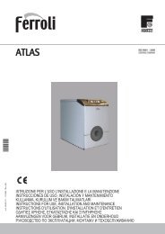
Prextherm RSW Quadra<br />
Pressurised steel boilers<br />
The PREXTHERM RSW<br />
Quadra series heat<br />
generators are<br />
pressurised combustion<br />
boilers with flame<br />
reversal in the<br />
combustion chamber<br />
and three flue<br />
gas passes.<br />
18 models<br />
available from<br />
92 to 1890kW<br />
Features and Benefits<br />
The shape design of the heat exchanger ensures an optimum ratio between the combustion<br />
volumes and the heat exchange surfaces<br />
The materials used ensure the long life of the boiler<br />
New turbulators improve the heat exchange of the flue gas and at the same time ensures a lower<br />
pressure drop<br />
A baffle plate has been fitted at the central heating system return inlet to improve the circulation of<br />
cold water towards the bottom of the boiler. This solution ensures more uniform distribution of the<br />
heat exchange fluid across the boiler’s heat exchange surface, achieving maximum heat exchange<br />
with less stress on the walls<br />
The tube bundle has been positioned above the combustion chamber, so that the flue gas is always<br />
discharged into a “hot”environment, preventing condensation forming<br />
The burner is not aligned with the combustion chamber, but rather has been moved downwards.<br />
This assists the reversal of the flame, reduces the pressure drop on the flue gas side and as a<br />
consequence extends the operating range of the generator<br />
The combustion chamber is completely cooled (even at the rear), to ensure a greater heat exchange<br />
surface and improve the distribution of the heating load across the walls<br />
The steel body is completely lined with an 80mm thick layer of glass wool, in turn covered by a sturdy<br />
layer of tearproof material<br />
The door can be hinged on the right-hand or left-hand side, has a double door stop with a newconcept<br />
locking and centring system. The door lining in the “Quadra” is made from ceramic fibre<br />
24
Vjltkm<br />
Rjl<br />
Pfdjlcrjq yjvth<br />
Ntgkjghjbpdjlbntkmyjcn<br />
m<br />
Gjktpyfz Ntgkjdfzvjoyjcnm<br />
Vfrc= hf,jxtt lfdktybt<br />
Vfrc= hf,jxfz ntvgthfnehf<br />
J,mtv rjnkjdjq djls<br />
Jg htccj djxyjt l fdktybt#Lfnf<br />
' ktrnhjgbnfybt<br />
Technical specifications<br />
92 107 152 190 240 300 350 399 525 600 720 820 940 1060 1250 1480 1600 1890<br />
Heat output min. kW 60 70 100 137 160 196 228 260 341 390 468 533 611 689 813 962 1040 1229<br />
max. kW 92 107 152 190 240 300 350 399 525 600 720 820 940 1060 1250 1480 1600 1890<br />
Heat input min. kW 64.3 75 107.3 147.4 170.9 209.5 242.5 277.5 364.5 417 502 566 651 731 884 1046 1128 1336<br />
max. kW 99.5 116 165 206 261 326 378 432 567 648 777 881 1011 1140 1359 1608 1736 2054<br />
Water content dm 3 120 120 185 185 235 300 360 365 405 465 735 735 850 1250 1250 1500 1500 1630<br />
Energy marking (Directive 92/42 EEC) ★★ ★★ ★★ ★★ ★★ ★★ ★★ ★★ ★★ ★★ ★★ ★★ ★★ ★★ ★★ ★★ ★★ ★★<br />
Efficiency at Pn max (Tm 70°C) % 92.48 92.00 92.30 91.95 92.25 92.05 92.51 92.30 92.50 92.56 92.71 93.10 92.95 93.05 92.00 92.03 92.15 92.01<br />
Efficiency at Pn min (Tm 70°C) % 93.33 93.20 94.30 92.99 93.60 93.50 95.25 93.70 93.55 93.49 93.30 94.20 93.80 96.20 93.20 93.48 93.55 93.51<br />
Efficiency at 30% Pn max (Tm 50°C) % 93.95 93.65 94.50 93.46 94.24 94.12 95.50 94.19 94.15 94.32 93.60 94.40 94.20 96.75 93.41 93.68 93.80 93.76<br />
Δt smokes-environment gas 150.9/105.9 161.5/118 161.6/119 167.1/115.7 162.5/109 167/115 159.9/97.9 161.5/113 159.4/115 157.9/108.9 157/120 148.2/100 153.8/105 151.6/96.7 179.6/121 176.3/108 173.6/107 176.7/107<br />
CO 2 gas 10 10 10 10 10 10 10 10 10 10 10 10 10 10 10 10 10 10<br />
CO 2 oil 13 13 13 13 13 13 13 13 13 13 13 13 13 13 13 13 13 13<br />
Specific Thermic load mW/m 2 h 34.3 36.8 32.3 40.4 41.3 42.2 41.1 44.3 47.7 46.1 42.3 48.2 47.0 39.2 46.2 44.8 48.4 51.0<br />
Volumetric Thermic load mW/m 2 h 1.10 1.28 1.17 1.47 1.53 1.48 1.45 1.35 1.26 1.20 1.25 1.42 1.44 1.26 1.51 1.34 1.44 1.58<br />
Shell loss* % 1.3 1.3 1.2 1.1 1.0 1.0 1.0 1.0 0.9 0.9 0.8 0.8 0.7 0.7 0.6 0.6 0.6 0.6<br />
Loss at chimney burner on % 6.22 6.7 6.7 6.95 6.75 6.95 6.49 6.7 6.6 6.54 6.49 6.1 6.35 6.25 7.4 7.37 7.25 7.39<br />
Loss at chimney burner off ** % 0.1 0.1 0.1 0.1 0.1 0.1 0.1 0.1 0.1 0.1 0.1 0.1 0.1 0.1 0.1 0.1 0.1 0.1<br />
Working pressure bar 6 6 6 6 6 6 6 6 6 6 6 6 6 6 6 6 6 6<br />
Water side pressure drop Δt 10°C Δp mbar 8 11 20 12 17 40 48 43 40 51 32 40 51 65 86 110 110 100<br />
Δt 20°C Δp mbar 2 2 5 3 4 9 13 16 12 16 10 18 16 20 25 32 32 29<br />
Combustion chamber Internal Ø mm 390 390 420 420 420 488 488 538 638 638 686 686 686 776 776 830 830 830<br />
Length mm 700 700 920 920 1170 1135 1385 1395 1385 1660 1670 1670 1854 2104 2250 2500 2500 2500<br />
Volume m 3 0.09 0.09 0.14 0.14 0.17 0.22 0.26 0.32 0.45 0.54 0.62 0.62 0.70 0.90 0.90 1.20 1.20 1.30<br />
Surface total m 2 2.9 2.9 4.7 4.7 5.8 7.1 8.5 9 11 13 17 17 20 27 27 33 33 37<br />
Flue gas side pressure drop Δp mbar 0.5 0.7 1.2 1.2 2.3 3.3 3.5 4.4 4.3 4.8 4.5 5.6 5.4 6 6.5 6.5 6.8 7<br />
Flue gas flow-rate gas Kg/h 150 175 249 312 394 492 571 652 856 979 1179 1329 1523 1720 2050 2426 2620 3099<br />
oil Kg/h 159 186 264 331 418 522 606 692 909 1039 1252 1411 1617 1825 2176 2576 2781 3290<br />
Boiler weight (empty) kg 260 260 350 350 440 480 550 590 860 970 1250 1250 1420 1580 2250 2650 2700 2850<br />
Dimensions Height mm 925 925 980 980 980 1100 1100 1100 1250 1250 1400 1400 1400 1580 1580 1730 1730 1730<br />
Width mm 760 760 810 810 810 950 950 950 1060 1060 1260 1260 1450 1450 1530 1530 1530 1530<br />
Length mm 1046 1046 1296 1296 1516 1546 1816 1817 1838 2098 2158 2158 2398 2420 2420 2722 2722 2722<br />
Connections T1 DN 2" 2" 2 1 /2 " 21 /2 " 21 /2 " 21 /2 " 21 /2 " 21 /2" 80 80 100 100 100 125 125 150 150 150<br />
T2 DN 2" 2" 2 1 /2 " 21 /2 " 21 /2 " 21 /2 " 21 /2 " 21 /2" 80 80 100 100 100 125 125 150 150 150<br />
T3 DN 1 1 /4 " 11 /4 " 11 /2 " 11 /2 " 11 /2 " 11 /2 " 11 /2 " 11 /2 " 2" 2" 21 /2 " 21 /2 " 21 /2" 3" 3" 100 100 100<br />
T4 DN 3 / 4 " 3 /4 " 3 /4 " 3 /4 " 3 /4 " 3 /4 " 3 /4 " 3 /4 " 3 /4 " 3 /4 " 3 /4 " 3 /4 " 3 /4 " 3 /4 " 3 /4 " 11 /2 " 11 /2 " 11 /2 "<br />
T5 Ø mm 200 200 220 220 220 220 220 220 250 250 350 350 350 400 400 450 450 450<br />
* Air Blocked, temperature 20ºC<br />
** Combustion air closed<br />
W<br />
L<br />
T3 - T1 - T2<br />
T3 T1 T2<br />
T2 - T1 - T3<br />
KEY<br />
T1 Central heating flow outlet<br />
T6<br />
H<br />
T5<br />
T5<br />
T2 Central heating return inlet<br />
T3 Expansion vessel attachment<br />
T4 Boiler drain<br />
T5 Flue attachment<br />
T4<br />
T4<br />
T6 Burner attachment fitting<br />
25
Prextherm RSW Tonda<br />
Pressurised steel boilers<br />
The PREXTHERM RSW<br />
Tonda series heat<br />
generators<br />
are pressurised<br />
combustion boilers<br />
with flame reversal<br />
in the combustion<br />
chamber and three<br />
flue gas passes.<br />
7 models available<br />
from 2360 to 6000kW<br />
Features and Benefits<br />
The shape design of the heat exchanger ensures an optimum ratio between the combustion<br />
volumes and the heat exchange surfaces<br />
The materials used ensure the long life of the boiler<br />
New turbulators improve the heat exchange of the flue gas and at the same time ensure a lower<br />
pressure drop<br />
A baffle plate has been fitted at the central heating system return inlet to improve the circulation of<br />
cold water towards the bottom of the boiler. This solution ensures more uniform distribution of the<br />
heat exchange fluid across the boiler’s heat exchange surface, achieving maximum heat exchange<br />
with less stress on the walls<br />
The tube bundle has been positioned above the combustion chamber, so that the flue gas is always<br />
discharged into a “hot”environment, preventing condensation forming<br />
The burner is not aligned with the combustion chamber, but rather has been moved downwards.<br />
This assists the reversal of the flame, reduces the pressure drop on the flue gas side and as a<br />
consequence extends the operating range of the generator<br />
The combustion chamber is completely cooled (even at the rear), to ensure a greater heat exchange<br />
surface and improve the distribution of the heating load across the walls<br />
The steel body is completely lined with an 80mm thick layer of glass wool, in turn covered by a sturdy<br />
layer of tearproof material<br />
The door can be hinged on the right-hand or left-hand side, has a double door stop with a newconcept<br />
locking and centring system. The door lining in the “Tonda” has a double cement lining plus<br />
an extra layer of insulating material<br />
26
Vjltkm<br />
Rjl<br />
Pfdjlcrjq yjvth<br />
Ntgkjghjbpdjlbntkmyjcn<br />
m<br />
Gjktpyfz Ntgkjdfzvjoyjcnm<br />
Vfrc= hf,jxtt lfdktybt<br />
Vfrc= hf,jxfz ntvgthfnehf<br />
J,mtv rjnkjdjq djls<br />
Jg h tccjd jxyjt lfdktybt#Lfnf<br />
' ktrnhjgbnfybt<br />
Technical specifications<br />
2360 3000 3600 4000 4500 5000 6000<br />
Heat output min. kW 1535 1950 2340 2600 2926 3251 3902<br />
max. kW 2360 3000 3600 4000 4500 5000 6000<br />
Heat input min. kW 1668 2113 2536 2819 3165 3515 4215<br />
max. kW 2565 3250 3900 4334 4868 5407 6483<br />
Water content dm 3 2150 2600 2950 4500 4950 6250 7000<br />
Energy marking (Directive 92/42 EEC) ★★ ★★ ★★ ★★ ★★ ★★ ★★<br />
Efficiency at Pn max (Tm 70°C) % 92.00 92.30 92.31 92.30 92.45 92.47 92.55<br />
Efficiency at Pn min (Tm 70°C) % 93.20 93.51 93.72 93.51 93.40 93.30 93.50<br />
Efficiency at 30% Pn max (Tm 50°C) % 93.65 93.76 94.21 93.76 94.05 93.90 94.35<br />
Δt smokes-environment gas 179.1/120 172.5/113 172.3/114 174.7/113 171.4/105 171.4/106 169.2/109<br />
CO 2 gas 10 10 10 10 10 10 10<br />
CO 2 oil 13 13 13 13 13 13 13<br />
Specific Thermic load mW/m 2 h 52.4 49.1 52.9 45.4 46.3 45.0 43.7<br />
Volumetric Thermic load mW/m 2 h 1.22 1.16 1.21 1.14 1.18 1.12 1.20<br />
Shell loss* % 0.5 0.5 0.5 0.4 0.4 0.4 0.4<br />
Loss at chimney burner on % 7.4 7.2 7.19 7.3 7.15 7.13 7.05<br />
Loss at chimney burner off ** % 0.1 0.1 0.1 0.1 0.1 0.1 0.1<br />
Working pressure bar 6 6 6 6 6 6 6<br />
Water side pressure drop Δt 10°C Δp mbar 150 145 190 250 280 200 215<br />
Δt 20°C Δp mbar 42 45 61 70 80 55 65<br />
Combustion chamber Internal Ø mm 980 1130 1130 1174 1174 1278 1278<br />
Length mm 2750 3000 3300 3300 3300 3300 3300<br />
Volume m 3 2.10 2.80 3.20 3.80 4.10 4.80 5.40<br />
Surface total m 2 45 61 68 88 97 111 137<br />
Flue gas side pressure drop Δp mbar 7.2 7.5 8.2 9.5 10.5 10.8 12.0<br />
Flue gas flow-rate gas Kg/h 3870 4904 5884 6539 7344 8158 9781<br />
oil Kg/h 4108 5205 6246 6941 7795 8660 10383<br />
Boiler weight (empty) kg 3900 5300 5800 7500 8000 9600 11500<br />
Dimensions Height mm 1950 2140 2140 2325 2325 2525 2525<br />
Width mm 1610 1800 1800 1980 1980 2180 2180<br />
Length mm 3232 3446 3816 4086 4436 4458 4958<br />
Connections T1 DN 150 200 200 200 200 250 250<br />
T2 DN 150 200 200 200 200 250 250<br />
T3 DN 100 125 125 125 125 150 150<br />
T4 DN 1 1 /2 " 1 1 /2 " 1 1 /2 " 1 1 /2 " 1 1 /2 " 1 1 /2 " 1 1 /2 "<br />
T5 Ø mm 450 500 500 600 600 650 650<br />
* Air Blocked, temperature 20ºC<br />
** Combustion air closed<br />
W<br />
T1 - T3 - T2<br />
T1<br />
L<br />
T3 T2 T2 - T3 - T1<br />
KEY<br />
T1 Central heating flow outlet<br />
T2 Central heating return inlet<br />
T6<br />
H<br />
T5<br />
T5<br />
T3 Expansion vessel attachment<br />
T4 Boiler drain<br />
T5 Flue attachment<br />
T4<br />
T4<br />
T6 Burner attachment fitting<br />
27
Prextherm RSH Quadra<br />
High efficiency pressurised steel boilers<br />
The PREXTHERM RSH<br />
Quadra series heat<br />
generators<br />
are pressurised<br />
combustion boilers<br />
with flame reversal<br />
in the combustion<br />
chamber and three<br />
flue gas passes.<br />
12 models<br />
available from<br />
92 to 940kW<br />
Features and Benefits<br />
The shape design of the heat exchanger ensures an optimum ratio between the combustion<br />
volumes and the heat exchange surfaces<br />
The materials used ensure the long life of the boiler<br />
New turbulators improve the heat exchange of the flue gas and at the same time ensure a lower<br />
pressure drop<br />
A baffle plate has been fitted at the central heating system return inlet to improve the circulation of<br />
cold water towards the bottom of the boiler. This solution ensures more uniform distribution of the<br />
heat exchange fluid across the boiler’s heat exchange surface, achieving maximum heat exchange<br />
with less stress on the walls<br />
The tube bundle has been positioned above the combustion chamber, so that the flue gas is always<br />
discharged into a “hot”environment, preventing condensation forming<br />
The burner is not aligned with the combustion chamber, but rather has been moved downwards.<br />
This assists the reversal of the flame, reduces the pressure drop on the flue gas side and as a<br />
consequence extends the operating range of the generator<br />
The combustion chamber is completely cooled (even at the rear), to ensure a greater heat exchange<br />
surface and improve the distribution of the heating load across the walls<br />
The steel body is completely lined with an 80mm thick layer of glass wool, in turn covered by a sturdy<br />
layer of tearproof material<br />
The door can be hinged on the right-hand or left-hand side, has a double door stop with a newconcept<br />
locking and centring system. The door lining in the “Quadra” is made from ceramic fibre<br />
28
Vjltkm<br />
Rjl<br />
Pfdjlcrjq yjvth<br />
Ntgkjghjbpdjlbntkmyjcn<br />
m<br />
Gjktpyfz Ntgkjdfzvjoyjcnm<br />
Vfrc= hf,jxtt lfdktybt<br />
Vfrc= hf,jxfz ntvgthfnehf<br />
J,mtv rjnkjdjq djls<br />
Jg htccj djxyjt l fdktybt#Lfnf<br />
' ktrnhjgbnfybt<br />
Technical specifications<br />
80 90 130 160 200 250 350 450 500 600 700 800<br />
Heat output min. kW 60 70 100 137 160 196 260 341 390 468 533 611<br />
max. kW 92 107 152 190 240 320 399 500 600 720 820 940<br />
Heat input min. kW 63.7 74.3 105.8 144.4 168.4 206 272.6 357 407.9 489.8 558.4 638.9<br />
max. kW 97.7 113.5 160.8 200.2 252.6 336.4 418.4 523.5 627.6 753.6 859.1 982.9<br />
Water content dm 3 120 185 235 304 362 337 405 471 735 850 850 1240<br />
Energy marking (Directive 92/42 EEC) ★★★ ★★★ ★★★ ★★★ ★★★ ★★★ ★★★ ★★★ ★★★ ★★★ ★★★ ★★★<br />
Efficiency at Pn max (Tm 70°C) % 94.19 94.27 94.52 94.92 95.02 95.15 95.37 95.52 95.62 95.56 95.47 96.00<br />
Efficiency at Pn min (Tm 70°C) % 95.40 95.50 95.75 95.44 95.71 95.84 96.06 96.21 96.31 96.25 96.16 96.34<br />
Efficiency at 30% Pn max (Tm 50°C) % 95.42 95.52 95.77 95.75 96.02 96.12 96.37 96.52 96.62 96.56 96.47 96.65<br />
Δt smokes-environment gas 112.9/85.6 111.1/83.4 107.8/80.1 101.1/82.7 101.1/79 98.2/76.8 95.5/73.6 92.2/70.3 92.2/70.3 93.5/78.4 97.8/75.8 93.8/71.9<br />
CO 2 gas 10 10 10 10 10 10 10 10 10 10 10 10<br />
CO 2 oil 13 13 13 13 13 13 13 13 13 13 13 13<br />
Specific Thermic load mW/m 2 h 31.7 22.7 26.2 26.3 28.2 35.5 36.2 38.4 35.2 36.0 41.0 34.8<br />
Volumetric Thermic load mW/m 2 h 1.08 0.81 0.94 0.91 0.97 1.05 0.92 0.96 1.01 1.07 1.22 1.09<br />
Shell loss* % 1.3 1.3 1.2 1.1 1.0 1.0 0.9 0.9 0.8 0.8 0.7 0.7<br />
Loss at chimney burner on % 4.51 4.43 4.28 3.98 3.98 3.85 3.73 3.58 3.58 3.6 3.83 3.65<br />
Loss at chimney burner off ** % 0.1 0.1 0.1 0.1 0.1 0.1 0.1 0.1 0.1 0.1 0.1 0.1<br />
Working pressure bar 6 6 6 6 6 6 6 6 6 6 6 6<br />
Water side pressure drop Δt 10°C Δp mbar 11 20 12 17 40 48 40 51 32 40 51 65<br />
Δt 20°C Δp mbar 2 5 3 4 9 13 12 16 10 18 16 20<br />
Combustion chamber Internal Ø mm 390 420 420 420 420 488 638 638 686 686 686 776<br />
Length mm 700 920 920 1170 1170 1135 1385 1660 1670 1670 1854 2104<br />
Volume m 3 0.09 0.14 0.17 0.22 0.26 0.32 0.45 0.54 0.62 0.70 0.70 0.90<br />
Surface total m 2 2.9 4.7 5.8 7.2 8.5 9 11 13 17 20 20 27<br />
Flue gas side pressure drop Δp mbar 0.7 1.2 1.2 2.3 3.3 3.5 4.3 4.8 4.5 5.6 5.4 6<br />
Flue gas flow-rate gas Kg/h 156 182 258 321 405 539 670 838 1005 1207 1376 1574<br />
oil Kg/h 161 186 264 329 415 553 687 860 1031 1238 1411 1615<br />
Boiler weight (empty) kg 260 350 350 440 480 550 860 970 1250 1250 1420 1580<br />
Dimensions Height mm 925 980 980 1100 1100 1100 1250 1250 1400 1400 1400 1580<br />
Width mm 760 810 810 950 950 950 1060 1060 1260 1450 1450 1450<br />
Length mm 1046 1296 1516 1546 1816 1817 1838 2098 2158 2398 2398 2420<br />
Connections T1 DN 2" 2 1 /2 " 21 /2 " 21 /2 " 21 /2 " 21 /2" 80 80 100 100 100 125<br />
T2 DN 2" 2 1 /2 " 21 /2 " 21 /2 " 21 /2 " 21 /2" 80 80 100 100 100 125<br />
T3 DN 1 1 /4 " 11 /2 " 11 /2 " 11 /2 " 11 /2 " 11 /2 " 2" 2" 21 /2 " 21 /2 " 21 /2 " 3"<br />
T4 DN 3 / 4 " 3 /4 " 3 /4 " 3 /4 " 3 /4 " 3 /4 " 3 /4 " 3 /4 " 3 /4 " 3 /4 " 3 /4 " 3 /4 "<br />
T5 Ø mm 200 220 220 220 220 220 250 250 350 350 350 400<br />
* Air Blocked, temperature 20ºC<br />
** Combustion air closed<br />
W<br />
L<br />
T3 - T1 - T2<br />
T3 T1 T2<br />
T2 - T1 - T3<br />
KEY<br />
T1 Central heating flow outlet<br />
T6<br />
H<br />
T5<br />
T5<br />
T2 Central heating return inlet<br />
T3 Expansion vessel attachment<br />
T4 Boiler drain<br />
T5 Flue attachment<br />
T4<br />
T4<br />
T6 Burner attachment<br />
29
Prextherm RSH Tonda<br />
High efficiency pressurised steel boilers<br />
The PREXTHERM RSH<br />
Tonda series heat<br />
generators<br />
are pressurised<br />
combustion boilers<br />
with flame reversal<br />
in the combustion<br />
chamber and three<br />
flue gas passes.<br />
6 models available<br />
from 1060 to 3000kW<br />
Features and Benefits<br />
The shape design of the heat exchanger ensures an optimum ratio between the combustion<br />
volumes and the heat exchange surfaces<br />
The materials used ensure the long life of the boiler<br />
New turbulators improve the heat exchange of the flue gas and at the same time ensure a lower<br />
pressure drop<br />
A baffle plate has been fitted at the central heating system return inlet to improve the circulation of<br />
cold water towards the bottom of the boiler. This solution ensures more uniform distribution of the<br />
heat exchange fluid across the boiler’s heat exchange surface, achieving maximum heat exchange with<br />
less stress on the walls<br />
The tube bundle has been positioned above the combustion chamber, so that the flue gas is always<br />
discharged into a “hot”environment, preventing condensation forming<br />
The burner is not aligned with the combustion chamber, but rather has been moved downwards. This<br />
assists the reversal of the flame, reduces the pressure drop on the flue gas side and as a consequence<br />
extends the operating range of the generator<br />
The combustion chamber is completely cooled (even at the rear), to ensure a greater heat exchange<br />
surface and improve the distribution of the heating load across the walls<br />
The steel body is completely lined with an 80mm thick layer of glass wool, in turn covered by a sturdy<br />
layer of tearproof material<br />
The door can be hinged on the right-hand or left-hand side, has a double door stop with a newconcept<br />
locking and centring system. The door lining in the “Tonda” has a double cement lining plus<br />
an extra layer of insulating material<br />
30
Vjltkm<br />
Rjl<br />
Pfdjlcrjq yjvth<br />
Ntgkjghjbpdjlbntkmyjcn<br />
m<br />
Gjktpyfz Ntgkjdfzvjoyjcnm<br />
Vfrc= hf,jxtt lfdktybt<br />
Vfrc= hf,jxfz ntvgthfnehf<br />
J,mtv rjnkjdjq djls<br />
Jg h tccjd jxyjt lfdktybt#Lfnf<br />
' ktrnhjgbnfybt<br />
Technical specifications<br />
900 1100 1300 1600 2000 2600<br />
Heat output min. kW 689 813 962 1229 1535 1950<br />
max. kW 1060 1250 1480 1845 2360 3000<br />
Heat input min. kW 719.9 848.2 1004.4 1291.2 1603.1 2033.7<br />
max. kW 1107.6 1304.2 1545.2 1930 2464.7 3128.8<br />
Water content dm 3 1490 1490 1620 1925 2600 2920<br />
Energy marking (Directive 92/42 EEC) ★★★ ★★★ ★★★ ★★★ ★★★ ★★★<br />
Efficiency at Pn max (Tm 70°C) % 95.72 95.86 95.8 95.60 95.77 95.90<br />
Efficiency at Pn min (Tm 70°C) % 96.41 96.55 96.46 95.80 96.39 96.59<br />
Efficiency at 30% Pn max (Tm 50°C) % 96.72 96.87 96.81 96.50 96.78 96.91<br />
Δt smokes-environment gas 94.4/72.5 91.3/69.3 92.7/70.6 97.1/77.3 95.5/73.4 92.7/70.6<br />
CO 2 gas 10 10 10 10 10 10<br />
CO 2 oil 13 13 13 13 13 13<br />
Specific Thermic load mW/m 2 h 32.1 37.8 40.0 41.0 38.6 44.1<br />
Volumetric Thermic load mW/m 2 h 0.93 1.08 1.18 0.92 0.88 0.97<br />
Shell loss* % 0.6 0.6 0.6 0.6 0.5 0.5<br />
Loss at chimney burner on % 3.68 3.54 3.60 3.80 3.73 3.60<br />
Loss at chimney burner off ** % 0.1 0.1 0.1 0.1 0.1 0.1<br />
Working pressure bar 6 6 6 6 6 6<br />
Water side pressure drop Δt 10°C Δp mbar 86 110 100 150 145 190<br />
Δt 20°C Δp mbar 25 32 29 42 45 61<br />
Combustion chamber Internal Ø mm 776 830 830 980 1130 1130<br />
Length mm 2250 2500 2500 2750 3000 3300<br />
Volume m 3 1.20 1.20 1.30 2.10 2.80 3.20<br />
Surface total m 2 33 33 37 45 61 68<br />
Flue gas side pressure drop Δp mbar 6.5 6.5 6.8 7 7.2 7.5<br />
Flue gas flow-rate gas Kg/h 1774 2088 2474 3091 3947 5010<br />
oil Kg/h 1819 2142 2538 3171 4049 5140<br />
Boiler weight (empty) kg 2250 2650 2850 3900 5300 5800<br />
Dimensions Height mm 1730 1730 1730 1950 2140 2140<br />
Width mm 1530 1530 1530 1610 1800 1800<br />
Length mm 2722 2722 2722 3232 3446 3816<br />
Connections T1 DN 150 150 150 150 200 200<br />
T2 DN 150 150 150 150 200 200<br />
T3 DN 100 100 100 100 125 125<br />
T4 DN 1 1 /2 " 1 1 /2 " 1 1 /2 " 1 1 /2 " 1 1 /2 " 1 1 /2 "<br />
T5 Ø mm 450 450 450 450 500 500<br />
* Air Blocked, temperature 20ºC<br />
** Combustion air closed<br />
W<br />
T1 - T3 - T2<br />
T1<br />
L<br />
T3 T2 T2 - T3 - T1<br />
KEY<br />
T1 Central heating flow outlet<br />
T6<br />
H<br />
T5<br />
T5<br />
T2 Central heating return inlet<br />
T3 Expansion vessel attachment<br />
T4 Boiler drain<br />
T5 Flue attachment<br />
T4<br />
T4<br />
T6 Burner attachment<br />
31
Industrial <strong>Heating</strong><br />
<strong>Ferroli</strong> Industrial <strong>Heating</strong> offers a range of<br />
boilers for markets worldwide, with outputs<br />
varying between 100 and 19500kW:<br />
• generators for the production of hot<br />
water, superheated water and steam<br />
(with flame reversal and 3 flue passes)<br />
• solid fuel generators for the production<br />
of hot water, superheated water and<br />
saturated steam<br />
Steam Generators<br />
Vapoprex LVP<br />
Steam output from 150 to 3000kg/h<br />
Low pressure steam boiler with three flue passes, two in furnace.<br />
Vapoprex HVP<br />
Steam output from 150 to 5000kg/h<br />
Medium pressure steam boiler with three flue passes, two in furnace.<br />
Vapoprex 3GF<br />
Steam output from 1700 to 8500kg/h<br />
Medium pressure steam boiler with three flue passes.<br />
Vapoprex 3GN<br />
Steam output from 2000 to 28000kg/h<br />
Medium pressure steam boiler with three flue passes.<br />
32
Hot water boilers<br />
Hot Water Prextherm RSW/RSH<br />
Heat output from 92 to 3600kW<br />
Hot water boiler with three flue passes, two in furnace.<br />
Prextherm T 3G<br />
Heat output from 1200 to 19500kW<br />
Hot water boiler with three flue passes, two in furnace.<br />
Superheated water boilers<br />
Prextherm T 3G ASL<br />
Heat output from 1200 to 6000kW<br />
Superheated water boiler max temperature 140°,<br />
with three flue passes.<br />
Prextherm ASH/ASL<br />
Heat output from 160 to 3500kW<br />
Superheated water boiler with three flue passes,<br />
two in furnace.<br />
Prextherm 3GN AS<br />
Heat output from 1400 to 19500kW<br />
Superheated water boiler with three flue passes.<br />
Prextherm 3GF<br />
1400 to 3000kW<br />
Superheated water boiler with three flue passes.<br />
33
Aquacyl Twin Coil<br />
High quality stainless steel hot water cylinder<br />
for use on unvented hot water systems<br />
Aquacyl twin coil cylinder is ideal<br />
for solar water heating.<br />
The lower coil can be heated by<br />
energy from the solar collector.<br />
If hot water is required at a higher<br />
temperature than can be achieved<br />
by solar energy alone, then a <strong>Ferroli</strong><br />
High Efficiency boiler fires and heats<br />
the upper coil to boost the water<br />
temperature. Alternatively the<br />
cylinder’s electric immersion<br />
heater(s) may be used to boost<br />
the hot water temperature.<br />
Features and Benefits<br />
Twin coil for fastest heat recovery<br />
No anode<br />
Easy to install<br />
Easy to commission<br />
Simple electrical installation<br />
Stylish appearance<br />
Long life stainless steel body<br />
Low density, low HCFC insulation ensures optimum efficiency<br />
Easy to adjust immersion heaters<br />
No internal expansion bubble to maintain<br />
All pipe and electrical connections are possible from cylinder ‘front’<br />
25 year guarantee plus nationwide cover from our own service engineers<br />
Special features<br />
Two 3kW immersion heaters fitted as standard (optional 6, 9 and 12kW heaters available)<br />
6kW titanium heaters available for hard water areas or for customers with bore holes<br />
34
Technical specifications<br />
875170 875200 875250 875300 875510 875000<br />
Storage capacity litres 170 200 250 300 500 1000<br />
Overall diameter mm 510 554 554 554 660 820<br />
Overall height mm 1200 1120 1330 1650 1835 2314<br />
Overall height with expansion vessel on top mm 1480 1400 1330 2110 FM FM<br />
Weight when full kg 220 250 310 360 556 1185<br />
Primary flow/return connections 3 / 4 " 3 / 4 " 3 / 4 " 3 / 4 " 1" 1"<br />
Cold feed/hot draw off connections 3 / 4 " 3 / 4 " 3 / 4 " 3 / 4 " 1" 1"<br />
Maximum water supply pressure bar 12 12 12 12 12 12<br />
System operating pressure bar 3 3 3 3 3 3<br />
Expansion vessel charge pressure bar 3 3 3 3 3 3<br />
Expansion relief valve set pressure bar 6 6 6 6 6 6<br />
Temp and pressure relief valve set pressure bar 7 7 7 7 7 7<br />
Temp and pressure relief valve lift temperature ºC 90 90 90 90 90 90<br />
Maximum primary work pressure bar 3 3 3 3 3 3<br />
Recommended maintenance Annual Annual Annual Annual Annual Annual<br />
Immersion heater 3kW 230/240V L= 355mm 1 1 1 1 1 1<br />
FM = Floor Mounted<br />
<strong>Ferroli</strong>’s Aquacyl cylinder range is<br />
easy to install and commission.<br />
Each model is supplied complete<br />
with all necessary temperature and<br />
pressure expansion valves and vessels.<br />
The Aquacyl cylinder vessel has a 25 year<br />
manufacturer’s guarantee as standard.<br />
35
Air Source Heat Pumps HXA<br />
Renewable energy<br />
The HXA series heat<br />
pumps – suitable for family<br />
houses or small apartment<br />
buildings. Heat pumps do<br />
not require gas connections<br />
or the installation of flues.<br />
Ideal for new build as well<br />
as being a cost effective<br />
retrofit solution in houses<br />
which currently rely upon<br />
liquid fuel systems (oil,<br />
LPG). The units can also be<br />
integrated with a solar<br />
heating system.<br />
Features and Benefits<br />
Remote thermostat<br />
Wired or wireless remote control unit<br />
Humidity control sensors for cooling mode<br />
Built-in microprocessor control unit to manage the heating / cooling circuit<br />
Expansion modules for management of multiple zones<br />
Integrated management of multiple units in cascade (max. 16)<br />
Legionella protection function<br />
Digital management of special tariff time bands<br />
Timer/programmer for timed domestic hot water production (with external storage cylinder)<br />
Built-in compressor oil frost protection system<br />
Outdoor probe for climate control supplied as standard<br />
Built-in room humidity control with humidity sensor (optional) for cooling in summer<br />
Control of solar heating system integration<br />
Operating hour counter for the compressor and the pumps<br />
Integrated management (with three heat output levels) of the supplementary electric heater (optional)<br />
The advanced microprocessor control unit can control the<br />
heating/cooling system, the domestic hot water storage cylinder<br />
and a solar heating system.<br />
36
NOMINAL performances – Radiant plants<br />
IP Base acoustic setting up (AB) 5.1 6.1 7.1 8.1 10.1 12.1 15.1 18.1<br />
<strong>Heating</strong> capacity kW 4.76 5.83 6.92 8.03 10.2 11.9 15.7 18.6<br />
A35W18 A2W35 A7W35<br />
Power input kW 1.21 1.49 1.87 2.28 2.86 3.39 4.28 5.29<br />
COP 3.93 3.91 3.70 3.52 3.57 3.51 3.67 3.52<br />
Water flow rate plant side l/h 823 1008 1195 1385 1749 2043 2702 3204<br />
Pressure drops plant side kPa 10 15 20 25 37 47 51 46<br />
<strong>Heating</strong> capacity kW 3.95 4.85 5.75 6.67 8.43 9.85 13.1 15.5<br />
Power input kW 1.19 1.47 1.84 2.24 2.81 3.31 4.17 5.16<br />
COP 3.32 3.30 3.13 2.98 3.00 2.98 3.14 3.00<br />
Water flow rate plant side l/h 684 838 994 1152 1453 1697 2251 2667<br />
Pressure drops plant side kPa 7 11 14 18 27 35 38 34<br />
Cooling capacity kW 5.12 6.27 7.43 8.60 10.8 12.6 16.7 19.8<br />
Power input kW 1.54 1.91 2.39 2.91 3.64 4.32 5.44 6.73<br />
EER 3.32 3.28 3.11 2.96 2.97 2.92 3.07 2.94<br />
Water flow rate plant side l/h 885 1085 1286 1490 1879 2190 2914 3448<br />
Pressure drops plant side kPa 12 17 22 28 41 53 58 52<br />
NOMINAL performances – Standard plants<br />
IP Base acoustic setting up (AB) 5.1 6.1 7.1 8.1 10.1 12.1 15.1 18.1<br />
<strong>Heating</strong> capacity kW 4.65 5.70 6.76 7.84 9.91 11.6 15.3 18.2<br />
A35W18 A2W35 A7W35<br />
Power input kW 1.44 1.78 2.23 2.72 3.40 4.02 5.06 6.27<br />
COP 3.23 3.20 3.03 2.88 2.91 2.89 3.02 2.90<br />
Water flow rate plant side l/h 806 989 1171 1357 1712 1999 2642 3146<br />
Pressure drops plant side kPa 10 14 19 24 35 45 49 45<br />
<strong>Heating</strong> capacity kW 3.84 4.72 5.59 6.49 8.19 9.58 12.7 15.1<br />
Power input kW 1.42 1.76 2.20 2.68 3.34 3.95 4.96 6.15<br />
COP 2.70 2.68 2.54 2.42 2.45 2.43 2.56 2.46<br />
Water flow rate plant side l/h 667 819 970 1124 1418 1656 2190 2607<br />
Pressure drops plant side kPa 7 10 14 18 26 33 36 33<br />
Cooling capacity kW 4.24 5.20 6.15 7.14 8.98 10.4 13.9 16.5<br />
Power input kW 1.50 1.85 2.31 2.80 3.50 4.14 5.21 6.46<br />
EER 2.83 2.81 2.66 2.55 2.57 2.51 2.67 2.55<br />
Water flow rate plant side l/h 729 894 1059 1229 1548 1802 2403 2849<br />
Pressure drops plant side kPa 8 12 16 21 30 39 42 38<br />
Data declared according to EN 14511. The values are referred to units without options and accessories.<br />
A35W7 = source : air in 35°C d.b. / plant : water in 12°C out 7°C<br />
A35W18 = source : air in 35°C d.b. / plant : water in 23°C out 18°C<br />
A7W45 = source : air in 7°C d.b. 6°C w.b. / plant : water in 40°C out 45°C<br />
A7W35 = source : air in 7°C d.b. 6°C w.b. / plant : water in 30°C out 35°C<br />
Dimensions and clearance<br />
5.1–6.1<br />
7.1–8.1<br />
10.1–12.1 15.1–18.1<br />
A mm 400 400 400<br />
B mm 600 600 600<br />
C mm 200 200 200<br />
H mm 900 1150 1450<br />
37
Air Source Heat Pumps HXP<br />
Reverse cycle (active reverse cycle) for OUTDOOR or INDOOR installation<br />
Suitable for family houses<br />
or small apartment<br />
buildings. Heat pumps<br />
do not require gas<br />
connections or the<br />
installation of flues. Ideal<br />
for newbuild as well as<br />
being a cost effective<br />
retrofit solution in houses<br />
which currently rely upon<br />
liquid fuel systems (oil,<br />
LPG). The units can also<br />
be integrated with a solar<br />
heating system.<br />
Features and Benefits<br />
Three-speed heating circuit pump on the unit<br />
Multistage high pressure heating circuit pump on the unit<br />
Multistage high efficiency heating circuit pump on the unit<br />
Snow protection cover (for outdoor installation)<br />
Three-stage supplementary electric heaters<br />
Remote thermostat<br />
Wired or wireless remote control unit<br />
Humidity control sensors in cooling mode<br />
Three-way valve for the management of domestic hot water on the unit<br />
Single-phase power supply (in versions up to 13kW)<br />
Built-in microprocessor control unit to manage the heating/cooling system<br />
Expansion modules for management of multiple zones<br />
Integrated management of multiple units in cascade (max.16)<br />
Legionella protection function<br />
Digital input for management of special tariff time bands<br />
Timer/programmer for timed domestic hot water production (with external storage cylinder)<br />
Outdoor probe for climate control supplied as standard<br />
Built-in room humidity control with humidity sensor (optional) for cooling in summer<br />
Control of solar heating system integration<br />
Operating hour counter for the compressor and pumps<br />
Integrated management (with three heat output levels) of the supplementary electric heater (optional)<br />
Ductable for indoor installation<br />
38
NOMINAL performances – Radiant plants<br />
IP Base acoustic setting up (AB) 11.1 13.1 16.1 18.1 21.1<br />
<strong>Heating</strong> capacity kW 11.1 12.8 15.3 18.1 21.0<br />
A35W18 A2W35 A7W35<br />
Power input kW 2.65 3.07 3.68 4.14 4.81<br />
COP 4.19 4.17 4.16 4.37 4.37<br />
Water flow rate plant side l/h 1922 2217 2632 3135 3619<br />
Pressure drops plant side kPa 14 18 24 13 17<br />
<strong>Heating</strong> capacity kW 9.26 10.7 12.7 15.1 17.4<br />
Power input kW 2.60 3.01 3.61 4.07 4.72<br />
COP 3.56 3.55 3.52 3.71 3.69<br />
Water flow rate plant side l/h 1600 1853 2199 2615 3013<br />
Pressure drops plant side kPa 10 13 18 9 12<br />
Cooling capacity kW 11.7 13.5 15.8 19.1 21.8<br />
Power input kW 3.68 4.27 5.11 5.77 6.70<br />
EER 3.18 3.16 3.09 3.31 3.25<br />
Water flow rate plant side l/h 2017 2328 2741 3293 3776<br />
Pressure drops plant side kPa 15 19 25 14 19<br />
NOMINAL performances – Standard plants<br />
IP Base acoustic setting up (AB) 11.1 13.1 16.1 18.1 21.1<br />
<strong>Heating</strong> capacity kW 10.9 12.5 15.0 17.7 20.5<br />
A35W7 A2W45 A7W45<br />
Power input kW 3.21 3.72 4.47 5.04 5.85<br />
COP 3.40 3.36 3.36 3.51 3.50<br />
Water flow rate plant side l/h 1894 2172 2590 3076 3545<br />
Pressure drops plant side kPa 14 17 23 13 17<br />
<strong>Heating</strong> capacity kW 8.99 10.4 12.3 14.6 16.9<br />
Power input kW 3.17 3.67 4.40 4.97 5.76<br />
COP 2.84 2.83 2.80 2.94 2.93<br />
Water flow rate plant side l/h 1561 1807 2138 2537 2937<br />
Pressure drops plant side kPa 10 13 17 9 12<br />
Cooling capacity kW 9.00 10.4 12.3 14.7 16.9<br />
Power input kW 3.41 3.96 4.73 5.35 6.20<br />
EER 2.64 2.63 2.60 2.75 2.73<br />
Water flow rate plant side l/h 1546 1785 2111 2523 2900<br />
Pressure drops plant side kPa 10 13 17 9 11<br />
Data declared according to EN 14511. The values are referred to units without options and accessories.<br />
A35W7 = source : air in 35°C d.b. / plant : water in 12°C out 7°C<br />
A35W18 = source : air in 35°C d.b. / plant : water in 23°C out 18°C<br />
A7W45 = source : air in 7°C d.b. 6°C w.b. / plant : water in 40°C out 45°C<br />
A7W35 = source : air in 7°C d.b. 6°C w.b. / plant : water in 30°C out 35°C<br />
Dimensions<br />
11.1–13.1–16.1 18.1–21.1<br />
A1 mm 730 880<br />
B1 mm 730 880<br />
B2 mm 450 465<br />
H mm 1470 1620<br />
Alow 600mm on all sides of the unit to gain accessibility<br />
for maintenance and control operations.<br />
39
Air Source Heat Pumps HMP<br />
Reverse cycle (active reverse cycle) for OUTDOOR or INDOOR installation<br />
Suitable for family houses<br />
or small apartment<br />
buildings. Heat pumps<br />
do not require gas<br />
connections or the<br />
installation of flues. Ideal<br />
for newbuild as well as<br />
being a cost effective<br />
retrofit solution in houses<br />
which currently rely upon<br />
liquid fuel systems (oil,<br />
LPG). The units can also<br />
be integrated with a solar<br />
heating system.<br />
Features and Benefits<br />
Three-speed heating circuit pump on the unit<br />
Multistage high pressure heating circuit pump on the unit<br />
Multistage high efficiency heating circuit pump on the unit<br />
Snow protection cover (for outdoor installation)<br />
Three-stage supplementary electric heaters<br />
Remote thermostat<br />
Wired or wireless remote control unit<br />
Humidity control sensors in cooling mode<br />
Three-way valve for the management of domestic hot water on the unit<br />
Single-phase power supply (in versions up to 13kW)<br />
Built-in microprocessor control unit to manage the heating/cooling system<br />
Expansion modules for management of multiple zones<br />
Integrated management of multiple units in cascade (max.16)<br />
Legionella protection function<br />
Digital input for management of special tariff time bands<br />
Timer/programmer for timed domestic hot water production (with external storage cylinder)<br />
Outdoor probe for climate control supplied as standard<br />
Built-in room humidity control with humidity sensor (optional) for cooling in summer<br />
Control of solar heating system integration<br />
Operating hour counter for the compressor and pumps<br />
Integrated management (with three heat output levels) of the supplementary electric heater (optional)<br />
Ductable for indoor installation<br />
40
NOMINAL performances – Radiant plants<br />
IP Base acoustic setting up (AB) 24.1 27.1 31.1 35.1 40.1 45.1<br />
<strong>Heating</strong> capacity kW 5.18 5.81 6.79 7.75 8.72 10.0<br />
A35W18 A2W35 A7W35<br />
Power input kW 5.18 5.81 6.79 7.75 8.72 10.0<br />
COP 4.54 4.63 4.52 4.43 4.54 4.52<br />
Water flow rate plant side l/h 4052 4641 5299 5905 6823 7793<br />
Pressure drops plant side kPa 21 18 23 28 25 32<br />
<strong>Heating</strong> capacity kW 19.5 22.3 25.6 28.5 32.8 37.5<br />
Power input kW 5.08 5.70 6.66 7.59 8.53 9.82<br />
COP 3.84 3.91 3.84 3.75 3.85 3.82<br />
Water flow rate plant side l/h 3377 3862 4416 4918 5663 6477<br />
Pressure drops plant side kPa 15 13 16 20 18 23<br />
Cooling capacity kW 24.5 28.0 32.0 35.6 41.0 46.9<br />
Power input kW 7.20 8.08 9.46 10.8 12.2 14.0<br />
EER 3.40 3.47 3.38 3.30 3.36 3.35<br />
Water flow rate plant side l/h 4242 4845 5535 6173 7104 8138<br />
Pressure drops plant side kPa 23 19 25 31 27 35<br />
NOMINAL performances – Radiant plants<br />
IP Base acoustic setting up (AB) 24.1 27.1 31.1 35.1 40.1 45.1<br />
<strong>Heating</strong> capacity kW 23.0 26.3 30.0 33.5 38.5 44.1<br />
A35W18 A2W35 A7W35<br />
Power input kW 6.29 7.05 8.25 9.42 10.5 12.2<br />
COP 3.66 3.73 3.64 3.56 3.67 3.61<br />
Water flow rate plant side l/h 3980 4553 5196 5805 6674 7629<br />
Pressure drops plant side kPa 21 17 22 27 24 31<br />
<strong>Heating</strong> capacity kW 18.9 21.7 24.9 27.7 31.9 36.4<br />
Power input kW 6.19 6.95 8.12 9.25 10.4 11.9<br />
COP 3.05 3.12 3.07 2.99 3.07 3.06<br />
Water flow rate plant side l/h 3285 3771 4310 4797 5527 6309<br />
Pressure drops plant side kPa 14 12 15 19 17 22<br />
Cooling capacity kW 19.1 21.8 24.8 27.6 31.8 36.4<br />
Power input kW 6.65 7.47 8.73 9.95 11.2 12.8<br />
EER 2.87 2.92 2.84 2.77 2.84 2.84<br />
Water flow rate plant side l/h 3278 3741 4273 4754 5474 6264<br />
Pressure drops plant side kPa 14 12 15 19 17 22<br />
Data declared according to EN 14511. The values are referred to units without options and accessories.<br />
A35W7 = source : air in 35°C d.b. / plant : water in 12°C out 7°C<br />
A35W18 = source : air in 35°C d.b. / plant : water in 23°C out 18°C<br />
A7W45 = source : air in 7°C d.b. 6°C w.b. / plant : water in 40°C out 45°C<br />
A7W35 = source : air in 7°C d.b. 6°C w.b. / plant : water in 30°C out 35°C<br />
Dimensions<br />
24.1 27.1–31.1–35.1 40.1–45.1<br />
A1 mm 880 1180 1480<br />
B1 mm 880 880 880<br />
B2 mm 465 465 465<br />
H mm 1620 1620 1620<br />
Alow 600mm on all sides of the unit to gain accessibility for<br />
maintenance and control operations.<br />
41
Solar –Aquasol XS<br />
Drain Back Solar Systems<br />
By having the pumping<br />
station and solar controller<br />
all factory fitted into one<br />
unit, the Aquasol XS storage<br />
unit takes significantly less<br />
time and cost to install.<br />
Connecting the electric<br />
wiring, solar coil, back up<br />
heating and hot water<br />
circuits is made simple.<br />
Features and Benefits<br />
Quick and easy installation<br />
Available in two sizes, the space saving all-in-one configuration makes the Aquasol XS<br />
convenient to site<br />
Pre-plumbed pipework saves on materials, reduces install time – saves costs for the home-owner<br />
Specifically developed, easy-to-use controls for simple set-up and system monitoring<br />
Additional heating coil and electric immersion element are included for supplementary heating of the<br />
stored hot water for legionella protection<br />
Revolutionary in-roof solar collectors, available in portrait or landscape, for both tile and slate roofs<br />
Built in Solar Fluid ‘Drain-Back’ system prevents the solar collector freezing or overheating<br />
No requirement for glycol based solar fluid. Simply fill with mains water<br />
Connect the heating coil to a <strong>Ferroli</strong> Optimax HE Plus System or OV condensing boiler for a complete<br />
household energy efficient heating solution<br />
All components are easy to access for commissioning and servicing<br />
Designed and manufactured to the highest specification<br />
10 year warranty on the Aquasol XS Cylinder<br />
42
Technical specifications<br />
Aquasol XS 200T – 24022FE<br />
Includes installation kit: (Monobloc Pressure Reducing Valve (PRV), Expansion Vessel,<br />
Tundish, Y Strainer, Brackets and Flex (where applicable))<br />
Solar storage – lower part of tank litres 100<br />
Back-up storage – upper part of tank litres 85<br />
Back-up heat exchanger m 2 /kW 0.75/25<br />
Electrical element kW 3kW<br />
Dimensions (HxWxD) mm 1275 x 598 x 590<br />
Weight empty kg 67<br />
Recommended collector type Thermic 42<br />
12mm flow. 15mm return. Col Loop Max L=m* m 27<br />
15mm flow. 15mm return. Col Loop Max L=m* m 22<br />
Aquasol XS 300T – ZU40030000<br />
Includes installation kit: (Monobloc Pressure Reducing Valve (PRV), Expansion Vessel,<br />
Tundish, Y Strainer, Brackets and Flex (where applicable))<br />
Solar storage = lower part of tank litres 150<br />
Back-up storage = upper part of tank litres 130<br />
Back-up heat exchanger m 2 /kW 0.90/30<br />
Electrical element kW 3<br />
Dimensions (HxWxD) mm 1785 x 598 x 590<br />
Weight empty kg 84<br />
Recommended collector type 2 x Thermic 28<br />
12mm flow. 15mm return. Col Loop Max L=m* m 22<br />
15mm flow. 15mm return. Col Loop Max L=m* m 18<br />
* Maximum pipe (10x8mm/15x13mm) length collector circuit (L=flow + return) without the need to install an additional Drain-Back tank.<br />
Solar Panel (in-roof)<br />
Product code 12021 12031 12035<br />
Model name 28S 42L 42P<br />
Height mm 1776 1776 2596<br />
Width mm 1751 2596 1776<br />
Depth mm 105 105 105<br />
Weight kg 60 84 84<br />
Gross panel area m 2 3.11 4.61 4.61<br />
Nett panel area m 2 2.75 4.12 4.12<br />
Zero loss collector efficiency 0.743 0.743 0.743<br />
Heat loss coefficient A1 W/m 2 K 3.194 3.194 3.194<br />
43
Solar –Aquacyl<br />
Drain Back Solar Systems<br />
Each system component is<br />
specified and supplied for<br />
individual siting and<br />
installation. Providing<br />
flexibility as the fundamental<br />
benefit of the Aquacyl system.<br />
The range of size options for<br />
each major part means that<br />
any property can be catered<br />
for. Furthermore, the ability<br />
to position them individually<br />
eradicates potential<br />
restrictions caused by internal<br />
layout or space constraints.<br />
Features and Benefits<br />
Individual system components for the ultimate flexibility of siting<br />
Three solar collector panel sizes to choose from and suitable for tile or slate roofs<br />
Five different sized twin coil cylinders and 4 sizes drain back vessel options for exact specification to<br />
the property needs<br />
Solar panels can be mounted to either sloping or flat roofs<br />
Extensive warranties on all components (Collectors – 10 years, Cylinder Vessel – 25 years)<br />
44
Technical specifications<br />
Aquacyl Twin Coil Cylinders<br />
See page 33 for full range specifications<br />
Solar Panel<br />
Product code 12021 12031 12035<br />
Model name 28S 42L 42P<br />
Height mm 1776 1776 2596<br />
Width mm 1751 2596 1776<br />
Depth mm 105 105 105<br />
Weight kg 60 84 84<br />
Gross panel area m 2 3.11 4.61 4.61<br />
Nett panel area m 2 2.75 4.12 4.12<br />
Zero loss collector efficiency 0.743 0.743 0.743<br />
Heat loss coefficient A1 W/m 2 K 3.194 3.194 3.194<br />
Pumping Station<br />
The essential heart of the Aquacyl solar solution.<br />
Product code<br />
ZU40021001<br />
The pumping station has a 6m pump head and comes complete with:<br />
• Built in controller for<br />
- system monitoring display<br />
- flow gauge<br />
- up to 3 temperature sensors<br />
- pump speed control<br />
- system function control<br />
• Pressure gauges<br />
• Pressure relief valve<br />
• Connections for filling and emptying<br />
Drain-back Units<br />
Product code 20131 20033 20136 20140<br />
Capacity litres 10 20 30 50<br />
External (HxWxD) mm 260 x 310 x 260 400 x 365 x 355 400 x 520 x 355 400 x 830 x 355<br />
Material Mild steel Mild steel Mild steel Mild steel<br />
Pressure tested bar 4.5 4.5 4.5 4.5<br />
Max peak temp °C 200 200 200 200<br />
Max collector array m 2 6 12.5 21 33<br />
45
Solar – Ecotop<br />
Pressurised solar heating for any home<br />
A bespoke solution for the<br />
ultimate flexibility – <strong>Ferroli</strong>’s<br />
Ecotop pressurised solar heating<br />
system can be tailored to meet<br />
all your hot water needs. The<br />
Ecotop installation is filled<br />
with a solar fluid that<br />
remains within the solar<br />
panel and pressurised<br />
sealed system. Each system<br />
component is specified<br />
and supplied for individual<br />
siting and installation.<br />
Features and Benefits<br />
Individual system components for the ultimate flexibility of siting<br />
Two portrait solar collector panel sizes to choose from both are suitable for<br />
tile or slate roofs with ‘on-roof’ fixing<br />
Five different sized twin coil cylinders for exact specification to the property needs<br />
Solar panels can be mounted on either sloping or flat roofs<br />
Easy installation with ‘click clamps’ and double O-ring joints<br />
Absorber of pure copper (12 tubes) with titanium oxide coating<br />
Pre mixed solar fluid<br />
Solar Keymark certification<br />
High SAP ratings<br />
Extensive warranties on all components (Collectors – 10 years, Cylinder Vessel – 25 years)<br />
46
Technical specifications<br />
Aquacyl Twin Coil Cylinders<br />
See page 33 for full range specifications<br />
Solar Panel<br />
Product code 0XCK1RXA 0XCK2RXA<br />
Model name Ecotop VF 2.0 Ecotop VF 2.3<br />
Height mm 1700 2000<br />
Width mm 1160 1160<br />
Depth mm 80 80<br />
Weight kg 35 43<br />
Gross panel area m 2 1.97 2.32<br />
Nett panel area m 2 1.87 2.21<br />
Zero loss collector efficiency 0.755 0.755<br />
Heat loss coefficient A1 W/m 2 K 3.720 3.720<br />
Twin Line Pumping Station<br />
The essential heart of the Aquacyl solar solution.<br />
Product code<br />
ZU40022001<br />
The twin line pumping station has a 6m pump head and comes complete with:<br />
• Built in controller for<br />
- system monitoring display<br />
- flow gauge<br />
- up to 3 temperature sensors<br />
- pump speed control<br />
- system function control<br />
• Pressure gauges<br />
• Pressure relief valve<br />
• Connections for filling and emptying<br />
The Ecotop basic solar kit consists of:<br />
Solar Collector(s) – depending on quantity required.<br />
Support Frame Box Kit(s) – used to support the solar panel on either sloping or flat roofs.<br />
Hydraulic Kit – used to make the hydraulic connections to the solar panel.<br />
Pump Station complete with solar controller.<br />
Solar Expansion Vessel – accommodates the expansion of the solar system fluid.<br />
Solar Expansion Vessel connection kit – to connect and support the expansion vessel.<br />
Interconnection kit – hydraulic connection for more than one panel installation.<br />
47
Designed and produced by GS2 Design<br />
Your local <strong>Ferroli</strong> stockist<br />
<strong>Ferroli</strong> Limited<br />
Lichfield Road, Branston Industrial Estate<br />
Burton on Trent, Staffordshire, DE14 3HD<br />
Sales t: 0843 479 4790 e: commercial@ferroli.co.uk<br />
Servicing t: 0843 479 0479 e: service@ferroli.co.uk<br />
Technical t: 0843 479 0479 e: technical@ferroli.co.uk<br />
www.ferroli.co.uk<br />
Calls to this number are charged at the national rate.<br />
Whilst every effort is taken to ensure the accuracy of the information contained within the<br />
brochure, the details are offered in good faith and <strong>Ferroli</strong> Ltd. accepts no liability for matters<br />
arising as a result of errors and/or omissions.<br />
The information in this brochure was correct at the time of printing, however specifications<br />
and designs may be changed owing to <strong>Ferroli</strong>’s policy of continuous product research and<br />
development. The technical specifications in the product instruction manual supersedes<br />
and should always be referred to during installation and maintenance.<br />
Reproduction of this publication, or any part, is not permitted without the written consent of<br />
<strong>Ferroli</strong> Ltd. Please contact our Marketing Communications via marketing@ferroli.co.uk for<br />
further information. The statutory rights of the consumer are not affected.<br />
<strong>Commercial</strong>/V3/06.12