4.7 fuel tank (carbu - harley-davidson-sweden.se
4.7 fuel tank (carbu - harley-davidson-sweden.se
4.7 fuel tank (carbu - harley-davidson-sweden.se

Create successful ePaper yourself
Turn your PDF publications into a flip-book with our unique Google optimized e-Paper software.
HOME<br />
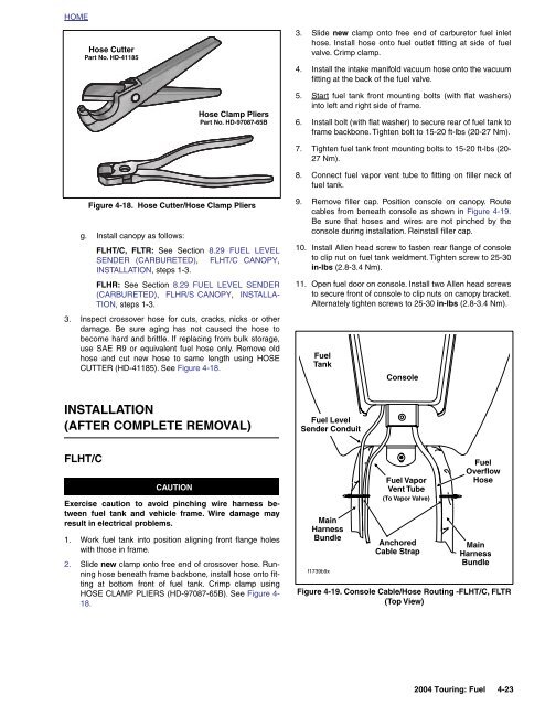
Ho<strong>se</strong> Cutter<br />
Part No. HD-41185<br />
3. Slide new clamp onto free end of <strong>carbu</strong>retor <strong>fuel</strong> inlet<br />
ho<strong>se</strong>. Install ho<strong>se</strong> onto <strong>fuel</strong> outlet fitting at side of <strong>fuel</strong><br />
valve. Crimp clamp.<br />
4. Install the intake manifold vacuum ho<strong>se</strong> onto the vacuum<br />
fitting at the back of the <strong>fuel</strong> valve.<br />
Ho<strong>se</strong> Clamp Pliers<br />
Part No. HD-97087-65B<br />
5. Start <strong>fuel</strong> <strong>tank</strong> front mounting bolts (with flat washers)<br />
into left and right side of frame.<br />
6. Install bolt (with flat washer) to <strong>se</strong>cure rear of <strong>fuel</strong> <strong>tank</strong> to<br />
frame backbone. Tighten bolt to 15-20 ft-lbs (20-27 Nm).<br />
7. Tighten <strong>fuel</strong> <strong>tank</strong> front mounting bolts to 15-20 ft-lbs (20-<br />
27 Nm).<br />
8. Connect <strong>fuel</strong> vapor vent tube to fitting on filler neck of<br />
<strong>fuel</strong> <strong>tank</strong>.<br />
Figure 4-18. Ho<strong>se</strong> Cutter/Ho<strong>se</strong> Clamp Pliers<br />
g. Install canopy as follows:<br />
FLHT/C, FLTR: See Section 8.29 FUEL LEVEL<br />
SENDER (CARBURETED), FLHT/C CANOPY,<br />
INSTALLATION, steps 1-3.<br />
FLHR: See Section 8.29 FUEL LEVEL SENDER<br />
(CARBURETED), FLHR/S CANOPY, INSTALLA-<br />
TION, steps 1-3.<br />
3. Inspect crossover ho<strong>se</strong> for cuts, cracks, nicks or other<br />
damage. Be sure aging has not cau<strong>se</strong>d the ho<strong>se</strong> to<br />
become hard and brittle. If replacing from bulk storage,<br />
u<strong>se</strong> SAE R9 or equivalent <strong>fuel</strong> ho<strong>se</strong> only. Remove old<br />
ho<strong>se</strong> and cut new ho<strong>se</strong> to same length using HOSE<br />
CUTTER (HD-41185). See Figure 4-18.<br />
9. Remove filler cap. Position console on canopy. Route<br />
cables from beneath console as shown in Figure 4-19.<br />
Be sure that ho<strong>se</strong>s and wires are not pinched by the<br />
console during installation. Reinstall filler cap.<br />
10. Install Allen head screw to fasten rear flange of console<br />
to clip nut on <strong>fuel</strong> <strong>tank</strong> weldment. Tighten screw to 25-30<br />
in-lbs (2.8-3.4 Nm).<br />
11. Open <strong>fuel</strong> door on console. Install two Allen head screws<br />
to <strong>se</strong>cure front of console to clip nuts on canopy bracket.<br />
Alternately tighten screws to 25-30 in-lbs (2.8-3.4 Nm).<br />
Fuel<br />
Tank<br />
Console<br />
INSTALLATION<br />
(AFTER COMPLETE REMOVAL)<br />
Fuel Level<br />
Sender Conduit<br />
FLHT/C<br />
CAUTION<br />
Exerci<strong>se</strong> caution to avoid pinching wire harness between<br />
<strong>fuel</strong> <strong>tank</strong> and vehicle frame. Wire damage may<br />
result in electrical problems.<br />
1. Work <strong>fuel</strong> <strong>tank</strong> into position aligning front flange holes<br />
with tho<strong>se</strong> in frame.<br />
2. Slide new clamp onto free end of crossover ho<strong>se</strong>. Running<br />
ho<strong>se</strong> beneath frame backbone, install ho<strong>se</strong> onto fitting<br />
at bottom front of <strong>fuel</strong> <strong>tank</strong>. Crimp clamp using<br />
HOSE CLAMP PLIERS (HD-97087-65B). See Figure 4-<br />
18.<br />
Main<br />
Harness<br />
Bundle<br />
f1739b9x<br />
Fuel Vapor<br />
Vent Tube<br />
(To Vapor Valve)<br />
Anchored<br />
Cable Strap<br />
Fuel<br />
Overflow<br />
Ho<strong>se</strong><br />
Main<br />
Harness<br />
Bundle<br />
Figure 4-19. Console Cable/Ho<strong>se</strong> Routing -FLHT/C, FLTR<br />
(Top View)<br />
2004 Touring: Fuel 4-23