4.7 fuel tank (carbu - harley-davidson-sweden.se
4.7 fuel tank (carbu - harley-davidson-sweden.se
4.7 fuel tank (carbu - harley-davidson-sweden.se

You also want an ePaper? Increase the reach of your titles
YUMPU automatically turns print PDFs into web optimized ePapers that Google loves.
HOME<br />
Clean Air Inlet Tube<br />
From Air Cleaner Backplate<br />
on Carbureted Models Only<br />
Fuel Vapor Vent Tube<br />
From Fuel Tank<br />
Purge Tube<br />
To Carburetor<br />
or Induction Module<br />
Fuel Vapor Vent Tube<br />
From Vapor Valve<br />
f1884x4x<br />
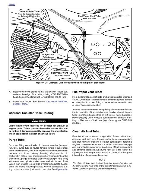
Figure 4-24. Charcoal Canister Tube/Ho<strong>se</strong> Routing (Left Side View)<br />
7. Rotate hold-down clamp so that the lip (with rubber pad)<br />
rests on the edge of the battery. Using a T40 TORX drive<br />
head, tighten the clamp bolt to 15-20 ft-lbs (20-27 Nm).<br />
8. Install rear fender. See Section 2.33 REAR FENDER,<br />
INSTALLATION.<br />
Charcoal Canister Ho<strong>se</strong> Routing<br />
1WARNING<br />
Verify that the vent tubes do not contact hot exhaust or<br />
engine parts. Tubes contain flammable vapors that can<br />
be ignited if damaged, possibly causing fire or explosion,<br />
which could result in death or <strong>se</strong>rious injury.<br />
Purge Tube:<br />
From top fitting on left side of charcoal canister (stamped<br />
“CARB”), purge tube is routed forward where it runs under<br />
frame crossmember, and then angles upward between crossmember<br />
and inner primary housing. Captured in clip<br />
anchored in hole at front of crossmember (rear and inboard of<br />
crui<strong>se</strong> hole), purge tube goes over crossover pipe, runs along<br />
left side of rear cylinder rocker cover and into tunnel of <strong>fuel</strong><br />
<strong>tank</strong>. It then cros<strong>se</strong>s to right side of motorcycle just to the rear<br />
of the top engine mounting bracket, where it connects to a fitting<br />
on the <strong>carbu</strong>retor (or induction module). See Figure 4-24.<br />
Fuel Vapor Vent Tube:<br />
From bottom fitting on left side of charcoal canister (stamped<br />
“TANK”), vent tube is routed forward and then upward in front<br />
of battery box to bottom fitting on vapor valve mounted to rear<br />
of upper frame crossmember.<br />
Another <strong>se</strong>ction connected to top fitting of vapor valve follows<br />
the inboard side of the main harness bundle, where it is captured<br />
in anchored cable strap on left side of frame backbone<br />
before passing under console pod/instrument console to fitting<br />
on filler neck of <strong>fuel</strong> <strong>tank</strong> (top of canopy on FLHR/C/S<br />
models).<br />
Clean Air Inlet Tube:<br />
From 90˚ elbow connector on right side of charcoal canister,<br />
clean air inlet tube runs forward under frame crossmember<br />
and then upward (inboard of starter connections) following<br />
angle of crossmember, where it is routed over crossover pipe<br />
and rear cylinder rocker cover into tunnel of <strong>fuel</strong> <strong>tank</strong> on right<br />
side of frame backbone. Tube turns right just to the rear of the<br />
top engine mounting bracket, where it connects to fitting on<br />
inboard side of air cleaner backplate.<br />
NOTE<br />
The clean air inlet tube is ab<strong>se</strong>nt on <strong>fuel</strong> injected models, so<br />
the fitting on the right side of the canister terminates in a 90˚<br />
elbow connector (the free end pointing down).<br />
4-30 2004 Touring: Fuel