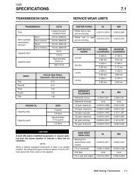
4.7 fuel tank (carbu - harley-davidson-sweden.se
4.7 fuel tank (carbu - harley-davidson-sweden.se
4.7 fuel tank (carbu - harley-davidson-sweden.se

Create successful ePaper yourself
Turn your PDF publications into a flip-book with our unique Google optimized e-Paper software.
HOME<br />
12. Connect <strong>fuel</strong> <strong>tank</strong> harness connector [13], 3-place Multilock,<br />
in front of battery. See Figure 4-17.<br />
13. Snap anchor of new cable strap into hole on left side of<br />
frame backbone. Tighten cable strap capturing main harness<br />
bundles, <strong>fuel</strong> level <strong>se</strong>nder conduit, and <strong>fuel</strong> vapor<br />
vent tube. Cut any excess cable strap material.<br />
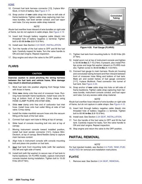
Convoluted<br />
Tubing<br />
NOTE<br />
Route <strong>fuel</strong> overflow ho<strong>se</strong> inboard of wire bundles on right side<br />
of frame, but do not capture in cable straps. See Figure 4-19.<br />
14. In<strong>se</strong>rt bolt through battery negative cable (black) into<br />
threaded hole of battery negative (-) terminal. Tighten<br />
bolt to 60-96 in-lbs (6.8-10.9 Nm).<br />
15. Install <strong>se</strong>at. See Section 2.24 SEAT, INSTALLATION.<br />
16. Turn the handle of the <strong>fuel</strong> valve to OFF and fill the <strong>fuel</strong><br />
<strong>tank</strong>. Carefully inspect for leaks. Turn the valve handle to<br />
ON and start engine. Repeat inspection.<br />
17. Stop engine and return the valve to the OFF position.<br />
FLHR/S<br />
CAUTION<br />
Exerci<strong>se</strong> caution to avoid pinching the wiring harness<br />
between the <strong>fuel</strong> <strong>tank</strong> and vehicle frame. Wire damage<br />
may result in electrical problems.<br />
1. Work <strong>fuel</strong> <strong>tank</strong> into position aligning front flange holes<br />
with tho<strong>se</strong> in frame.<br />
2. Slide new clamp onto free end of crossover ho<strong>se</strong>. Running<br />
ho<strong>se</strong> beneath frame backbone, install ho<strong>se</strong> onto fitting<br />
at bottom front of <strong>fuel</strong> <strong>tank</strong>. Crimp clamp using<br />
HOSE CLAMP PLIERS (HD-97087-65B).<br />
3. Slide new clamp onto free end of <strong>carbu</strong>retor <strong>fuel</strong> inlet<br />
ho<strong>se</strong>. Install ho<strong>se</strong> onto <strong>fuel</strong> outlet fitting at side of <strong>fuel</strong><br />
valve. Crimp clamp.<br />
4. Install the intake manifold vacuum ho<strong>se</strong> onto the vacuum<br />
fitting at the back of the <strong>fuel</strong> valve.<br />
5. Connect <strong>fuel</strong> vapor vent tube to fitting at top of canopy.<br />
6. Slide head of console mounting bolt into slot at top of<br />
canopy.<br />
7. Moving instrument console toward installed position,<br />
install <strong>fuel</strong> level <strong>se</strong>nder connector [141], 3-place Mini-<br />
Deutsch, at top of canopy. Bend flexible clamp to capture<br />
main harness conduit.<br />
8. Align hole in instrument console with console mounting<br />
bolt and place into position on <strong>fuel</strong> <strong>tank</strong>.<br />
9. Start <strong>fuel</strong> <strong>tank</strong> front mounting bolts (with flat washers)<br />
into left and right side of frame.<br />
10. Install bolt (with flat washer) to <strong>se</strong>cure rear of <strong>fuel</strong> <strong>tank</strong> to<br />
frame backbone. On FLHRS models, capture instrument<br />
console bracket during installation. Tighten bolt to 15-20<br />
ft-lbs (20-27 Nm).<br />
8870<br />
11. Tighten <strong>fuel</strong> <strong>tank</strong> front mounting bolts to 15-20 ft-lbs (20-<br />
27 Nm).<br />
12. Install acorn nut at top of instrument console and tighten<br />
to 50-90 in-lbs (5.7-10.2 Nm). If pre<strong>se</strong>nt, also install Phillips<br />
screw and large flat washer (ab<strong>se</strong>nt on FLHRS models).<br />
Tighten screw to 36-60 in-lbs (4.1-6.8 Nm).<br />
13. Connect <strong>fuel</strong> gauge to main harness. Route pin housing<br />
and convoluted tubing forward and then inboard between<br />
front of crossover ho<strong>se</strong> fitting and bottom of <strong>fuel</strong> <strong>tank</strong>.<br />
Mate pin and socket halves of <strong>fuel</strong> gauge connector<br />
[117], 4-place Multilock. Feed connector into tunnel of<br />
<strong>fuel</strong> <strong>tank</strong>. See Figure 4-20.<br />
14. Snap anchor of new cable strap into hole on left side of<br />
frame backbone. Tighten cable strap capturing main harness<br />
bundle, instrument console conduit, and <strong>fuel</strong> vapor<br />
vent tube. Cut any excess cable strap material.<br />
NOTE<br />
Route <strong>fuel</strong> overflow ho<strong>se</strong> inboard of wire bundles on right side<br />
of frame, but do not capture in cable straps. See Figure 4-19.<br />
15. In<strong>se</strong>rt bolt through battery negative cable (black) into<br />
threaded hole of battery negative (-) terminal. Tighten<br />
bolt to 60-96 in-lbs (6.8-10.9 Nm).<br />
16. Install <strong>se</strong>at. See Section 2.24 SEAT, INSTALLATION.<br />
17. Turn the handle of the <strong>fuel</strong> valve to OFF and fill the <strong>fuel</strong><br />
<strong>tank</strong>. Carefully inspect for leaks. Turn the valve handle to<br />
ON and start engine. Repeat inspection.<br />
18. Stop engine and return the valve to the OFF position.<br />
PARTIAL REMOVAL<br />
NOTE<br />
For <strong>fuel</strong> injected models, <strong>se</strong>e Section 9.4 FUEL TANK (FUEL<br />
INJECTED) for removal and installation instructions.<br />
FLHT/C<br />
Figure 4-20. Fuel Gauge (FLHR/S)<br />
1. Remove <strong>se</strong>at. See Section 2.24 SEAT, REMOVAL.<br />
4-24 2004 Touring: Fuel