SR420 Rotary Wing Mower - Operator Manual - McConnel
SR420 Rotary Wing Mower - Operator Manual - McConnel
SR420 Rotary Wing Mower - Operator Manual - McConnel
You also want an ePaper? Increase the reach of your titles
YUMPU automatically turns print PDFs into web optimized ePapers that Google loves.
Publication 608<br />
July 2009<br />
Part No. 22674.08<br />
McCONNEL<br />
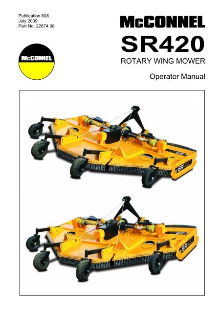
<strong>SR420</strong><br />
ROTARY WING MOWER<br />
<strong>Operator</strong> <strong>Manual</strong>
IMPORTANT<br />
VERIFICATION OF WARRANTY REGISTRATION<br />
DEALER WARRANTY INFORMATION & REGISTRATION VERIFICATION<br />
It is imperative that the selling dealer registers this machine with <strong>McConnel</strong> Limited within<br />
7 days of delivery to the end user – failure to do so may affect the validity of the machine<br />
warranty.<br />
To register machines go to the <strong>McConnel</strong> Limited web site at www.mcconnel.com, log<br />
onto ‘Dealer Inside’ and select the ‘Machine Registration button’ which can be found in<br />
the Service Section of the site. Confirm to the customer that the machine has been<br />
registered in the section below.<br />
Should you experience any problems registering a machine in this manner please contact<br />
the <strong>McConnel</strong> Service Department on 01584 875848.<br />
Registration Verification<br />
Dealer Name: ……………………..…………………………………………………………….<br />
Dealer Address: …….………………………………………………………………………….<br />
Customer Name: ……………………..…………………………………………………………<br />
Date of Warranty Registration: ……/……/...…… Dealer Signature: ………………..……<br />
NOTE TO CUSTOMER / OWNER<br />
Please ensure that the above section above has been completed and signed by the selling<br />
dealer to verify that your machine has been registered with <strong>McConnel</strong> Limited.<br />
IMPORTANT: During the initial ‘bedding in’ period of a new machine it is the customer’s responsibility<br />
to regularly inspect all nuts, bolts and hose connections for tightness and re-tighten if required. New<br />
hydraulic connections occasionally weep small amounts of oil as the seals and joints settle in – where<br />
this occurs it can be cured by re-tightening the connection – refer to torque settings chart below. The<br />
tasks stated above should be performed on an hourly basis during the first day of work and at least<br />
daily thereafter as part of the machines general maintenance procedure.<br />
TORQUE SETTINGS FOR HYDRAULIC FITTINGS<br />
HYDRAULIC HOSE ENDS<br />
PORT ADAPTORS WITH BONDED SEALS<br />
BSP Setting Metric BSP Setting Metric<br />
1/4” 18 Nm 19 mm 1/4” 34 Nm 19 mm<br />
3/8” 31 Nm 22 mm 3/8” 47 Nm 22 mm<br />
1/2” 49 Nm 27 mm 1/2” 102 Nm 27 mm<br />
5/8” 60 Nm 30 mm 5/8” 122 Nm 30 mm<br />
3/4” 80 Nm 32 mm 3/4” 149 Nm 32 mm<br />
1” 125 Nm 41 mm 1” 203 Nm 41 mm<br />
1.1/4” 190 Nm 50 mm 1.1/4” 305 Nm 50 mm<br />
1.1/2” 250 Nm 55 mm 1.1/2” 305 Nm 55 mm<br />
2” 420 Nm 70 mm 2” 400 Nm 70 mm
WARRANTY POLICY<br />
WARRANTY REGISTRATION<br />
All machines must be registered, by the selling dealer with <strong>McConnel</strong> Ltd, before delivery to the end user.<br />
On receipt of the goods it is the buyer’s responsibility to check that the Verification of Warranty Registration<br />
in the <strong>Operator</strong>’s <strong>Manual</strong> has been completed by the selling dealer.<br />
1. LIMITED WARRANTIES<br />
1.01. All machines supplied by <strong>McConnel</strong> Limited are warranted to be free from defects in material and<br />
workmanship from the date of sale to the original purchaser for a period of 12 months, unless a<br />
different period is specified.<br />
1.02. All spare parts supplied by <strong>McConnel</strong> Limited are warranted to be free from defects in material and<br />
workmanship from the date of sale to the original purchaser for a period of 6 months.<br />
1.03. The manufacturer will replace or repair for the purchaser any part or parts found, upon examination at<br />
its factory, to be defective under normal use and service due to defects in material or workmanship.<br />
Returned parts must be complete and unexamined.<br />
1.04. This warranty does not apply to any part of the goods, which has been subjected to improper or<br />
abnormal use, negligence, alteration, modification, fitment of non-genuine parts, accident damage, or<br />
damage resulting from contact with overhead power lines, damage caused by foreign objects (e.g.<br />
stones, iron, material other than vegetation), failure due to lack of maintenance, use of incorrect oil or<br />
lubricants, contamination of the oil, or which has served its normal life. This warranty does not apply to<br />
any expendable items such as blades, flails, flap kits, skids, soil engaging parts, shields, guards, wear<br />
pads or pneumatic tyres.<br />
1.05. Temporary repairs and consequential loss - i.e. oil, downtime and associated parts are specifically<br />
excluded from the warranty.<br />
1.06. Warranty on hoses is limited to 12 months and does not include hoses which have suffered external<br />
damage. Only complete hoses may be returned under warranty, any which have been cut or repaired<br />
will be rejected.<br />
1.07. Machines must be repaired immediately a problem arises. Continued use of the machine after a<br />
problem has occurred can result in further component failures, for which <strong>McConnel</strong> Ltd cannot be held<br />
liable, and may have safety implications.<br />
1.08. Except as provided herein, no employee, agent, dealer or other person is authorised to give any<br />
warranties of any nature on behalf of <strong>McConnel</strong> Ltd.<br />
1.09. For machine warranty periods in excess of 12 months the following additional exclusions shall apply:<br />
1) Hoses, external seals, exposed pipes and hydraulic tank breathers.<br />
2) Filters.<br />
3) Rubber mountings.<br />
4) External electric wiring.<br />
N.B. Warranty cover will be invalid if any non-genuine parts have been fitted or used. Use of nongenuine<br />
parts may seriously affect the machine’s performance and safety. <strong>McConnel</strong> Ltd. cannot be<br />
held responsible for any failures or safety implications that arise due to the use of non-genuine<br />
parts.
2. REMEDIES AND PROCEDURES<br />
2.01. The warranty is not effective unless the Selling Dealer registers the machine, via the <strong>McConnel</strong> web<br />
site and confirms the registration to the purchaser by completing the Verification of Warranty<br />
Registration in the operator’s manual.<br />
2.02. Any fault must be reported to an authorised <strong>McConnel</strong> dealer as soon as it occurs. Continued use of a<br />
machine, after a fault has occurred, can result in further component failure for which <strong>McConnel</strong> Ltd<br />
cannot be held liable.<br />
2.03. Repairs should be undertaken within two days of the failure. Claims submitted for repairs undertaken<br />
more than 2 weeks after a failure has occurred, or 2 days after the parts were supplied will be rejected,<br />
unless the delay has been authorised by <strong>McConnel</strong> Ltd.<br />
2.04. All claims must be submitted, by an authorised <strong>McConnel</strong> Service Dealer, within 30 days of the date of<br />
repair.<br />
2.05. Following examination of the claim and parts the manufacture will pay, at their discretion, for any valid<br />
claim the cost of any parts and an appropriate labour allowance if applicable.<br />
2.06. The submission of a claim is not a guarantee of payment.<br />
2.07. Any decision reached by <strong>McConnel</strong> Ltd. is final.<br />
3. LIMITATION OF LIABILITY<br />
3.01. The manufacturer disclaims any express (except as set forth herein) and implied warranties with<br />
respect to the goods including, but not limited to, merchantability and fitness for a particular purpose.<br />
3.02. The manufacturer makes no warranty as to the design, capability, capacity or suitability for use of the<br />
goods.<br />
3.03. Except as provided herein, the manufacturer shall have no liability or responsibility to the purchaser or<br />
any other person or entity with respect to any liability, loss, or damage caused or alleged to be caused<br />
directly or indirectly by the goods including, but not limited to, any indirect, special, consequential, or<br />
incidental damages resulting from the use or operation of the goods or any breach of this warranty.<br />
Notwithstanding the above limitations and warranties, the manufacturer’s liability hereunder for<br />
damages incurred by the purchaser or others shall not exceed the price of the goods.<br />
3.04. No action arising out of any claimed breach of this warranty or transactions under this warranty may be<br />
brought more than one (1) year after the cause of the action has occurred.<br />
4. MISCELLANEOUS<br />
4.01. The manufacturer may waive compliance with any of the terms of this limited warranty, but no waiver<br />
of any terms shall be deemed to be a waiver of any other term.<br />
4.02. If any provision of this limited warranty shall violate any applicable law and is held to be unenforceable,<br />
then the invalidity of such provision shall not invalidate any other provisions herein.<br />
4.03. Applicable law may provide rights and benefits to the purchaser in addition to those provided herein.
EC DECLARATION OF CONFORMITY<br />
Conforming to EEC Machinery Directive 98/37/EC*<br />
We,<br />
McCONNEL LIMITED,<br />
Temeside Works, Ludlow, Shropshire SY8 1JL.<br />
Declare under our sole responsibility that:<br />
The product (type) ………………………………………………………………………..<br />
Tractor Mounted <strong>Rotary</strong> <strong>Wing</strong> <strong>Mower</strong><br />
…………………………………………………………………………………………….<br />
Product Code ……………………………………………………………………………..<br />
<strong>SR420</strong><br />
Serial No. & Date ……………………………………. Type ……………………………<br />
Manufactured by the above company/* …………………………………………..………<br />
…………………………………………………………………………………………….<br />
(* insert business name and full address if not stated above)<br />
Complies with the required provisions of the Machinery Directive 98/37/EC, * previously<br />
Directive 89/392/EEC as amended by Directives 91/368/EEC, 93/44/EEC and 93/68/EEC.<br />
The machinery directive is supported by;<br />
BS EN ISO 12100:2003 Safety of Machinery. This standard is made up of two<br />
parts; Part 1 Terminology, methodology, Part 2 Technical Specifications.<br />
BS EN 1050 Safety of machinery - Principles of risk assessment.<br />
and other national standards associated with its design and construction as listed in<br />
the Technical File.<br />
The Machinery Directive is fully implemented into UK law by means of the Supply of<br />
Machinery (Safety) Regulations 1992 (SI 1992/3073) as amended by The Supply of<br />
Machinery (Safety) (Amendment) Regulations 1994 (SI 1994/2063).<br />
Signed ………………………..…………………………………………………….……..<br />
on behalf of McCONNEL LIMITED<br />
Responsible Person<br />
Status: Chief Design Engineer Date: July 2009
LIST OF CONTENTS<br />
Page No.<br />
Introduction 1<br />
Tractor Requirements 1<br />
Safety Information 2<br />
Safety Decals 5<br />
Tractor Attachment 6<br />
PTO Shaft 6<br />
Machine Setup 7<br />
Operation 8<br />
Transportation 9<br />
Machine Protection - Slip Clutch 9<br />
Service & Maintenance 10<br />
Troubleshooting Guide 16
INTRODUCTION<br />
The <strong>SR420</strong> <strong>Rotary</strong> <strong>Wing</strong> <strong>Mower</strong> is a heavy duty rotary mower primarily designed for set-aside,<br />
stubble and pasture topping work. With a cutting width of 4.2m they are suitable for use with<br />
tractors of between 85 and 120HP.<br />
The cutting height of the machine is controlled and regulated via the rear centre deck wheels<br />
and adjustable wing skids with addition wing wheels offered as an option.<br />
The wings of the machine ‘float’ mechanically during work to eliminate ram seal wear and are<br />
raised by independent single acting hydraulic rams for transportation of the machine –<br />
mechanical lift locks are provided for complete safety. Power from the tractor to the machine is<br />
transferred via a series of gearboxes and PTO shafts with slip clutch protection to absorb shock<br />
loads and protect driveline components.<br />
For personal safety and protection of components the machines should never be used to<br />
perform tasks they were not designed to do.<br />
TRACTOR REQUIRMENTS<br />
The tractors used should be:<br />
Minimum of 85HP.<br />
Equipped with Category 2 three-point linkage.<br />
Fitted with Check Chains and/or Stabilisers and correctly tightened (We particularly<br />
recommend 'turnbuckle' type Check Chains).<br />
Minimum weight of 3700kg.<br />
1000RPM PTO.<br />
Equipped with 1 external hydraulic service, single acting with float facility for wings.<br />
Sufficient weight on the front wheels to ensure stability during transportation and work.<br />
Extra ballast should be added if required.<br />
Before attachment; set lift rods to equal length and ensure position control is selected -<br />
never attempt to hitch in draft control.<br />
1
SAFETY<br />
Safety Information<br />
Read, Understand and Follow the Safety Messages - Serious injury or death may occur unless<br />
care is taken to follow the warnings and instructions given in the safety messages,<br />
CAUTION!<br />
WARNING!<br />
DANGER!<br />
The lowest level of Safety Message; warns of possible injury.<br />
Serious injury or possible death.<br />
Imminent death/critical injury.<br />
Never operate the tractor or machinery until you have read and completely understand this<br />
manual and the tractor operator’s manual and each of the safety messages found in the<br />
manuals and those displayed on the tractor and implement.<br />
DANGER!<br />
DO NOT attempt any maintenance of or adjustment to the machine while it is<br />
running. Before carrying out any work on the machine follow the three safety<br />
instructions below:<br />
a<br />
b<br />
c<br />
LOWER THE MACHINE ON TO THE GROUND<br />
PUT THE PTO OUT OF GEAR<br />
STOP THE TRACTOR ENGINE<br />
WARNING! The operator and all support personnel must wear the appropriate safety clothing<br />
i.e. safety glasses and safety shoes at all times for protection from injury by<br />
objects thrown from the machine.<br />
DANGER!<br />
DANGER!<br />
DANGER!<br />
CAUTION!<br />
Never allow passengers especially children to ride on the tractor or implement.<br />
Falling off can kill.<br />
Do not mount or dismount the tractor or machine while it is moving. Mount or<br />
dismount only when stopped – falling off can kill.<br />
At all times ensure that the PTO shaft guard is in position, securely fitted and in<br />
good condition and that the tractor PTO shaft shield is fitted.<br />
Replace the PTO shaft guard if any of the following are evident:- guard cracked or<br />
damaged any part of the PTO shaft exposed. Ensure the PTO shaft guard is free<br />
to rotate and the anti-rotation chains are securely fitted and effective.<br />
WARNING! Ensure that the correct guards are properly fitted to the machine and tractor at all<br />
times and check that they are in good condition. Ensure you have the correct<br />
guards fitted for the type of operation being performed. Missing or damaged<br />
guards must be replaced immediately.<br />
DANGER! AVOID WIRE. It can be extremely dangerous if wire catches in the blades of<br />
the machine, and every care must be taken to ensure this will not happen.<br />
Inspect the working area before commencing. Remove all loose wire and<br />
obstructions and clearly mark those that are fixed so that you can avoid them.<br />
Any unusual noise from the cutting unit area indicates that the blades may have<br />
been fouled by an obstruction. A visual indication that wire has become<br />
entangled may be a sudden movement of the vegetation ahead of the machine.<br />
In any such event STOP the tractor engine INSTANTLY. On no account move<br />
the machine until blades have completely stopped. When the machine has<br />
stopped inspect it and remove any obstruction that may be present. If working<br />
under a raised machine ensure that it is safely supported. Before working on<br />
the machine always stop the tractor engine and remove the ignition key.<br />
2
SAFETY<br />
WARNING! While the tractor is running all personnel should keep well clear of the area<br />
around the machine as there are numerous crushing, shearing, impact dangers<br />
caused by the machine operation.<br />
DANGER!<br />
DANGER!<br />
DANGER!<br />
DANGER!<br />
Do not operate with wings raised off the ground. Operating with the wings<br />
raised exposes the blades and can cause objects to be thrown and there is also<br />
danger of entanglement in or being hit by rotating blades.<br />
Do not work under a wing in the raised position unless it is supported on blocks<br />
or propped. A sudden or inadvertent fall by one of these components could<br />
cause serious injury or even death.<br />
These machines are capable under adverse conditions of throwing objects<br />
great distances at high velocity. CHECK the blades for wear and the<br />
attachment bolts for tightness every day during work .A few moments whenever<br />
the machine is stopped, e.g. whenever removing obstructions, will help reduce<br />
blade wear or loss.<br />
Keep your forward speed to a level appropriate to the operating conditions.<br />
High-speed manoeuvres are very dangerous, particularly on uneven ground<br />
where there is risk of overturning.<br />
DANGER! Keep a careful watch for passers-by who may inadvertently get in the way of cut<br />
material being ejected from the machine. These machines are capable under<br />
adverse conditions of throwing objects great distances at high velocity. Stop the<br />
blades until all people are well clear.<br />
WARNING! Extreme care should be taken when operating near loose objects such as gravel,<br />
rocks, wire, and other debris. Inspect the area before mowing. Foreign objects<br />
should be removed from the site to prevent machine damage and/or bodily<br />
injury or even death. Any objects that cannot be removed must be clearly<br />
marked and carefully avoided by the operator. Stop mowing immediately if<br />
blades strike a foreign object. Repair all damage and make certain the blade<br />
and carrier are still balanced before resuming cutting operations.<br />
WARNING! Transport the machine only at safe speeds. Serious accidents and injuries can<br />
result from operating this equipment at unsafe speeds<br />
DANGER!<br />
When the wings are folded for transport, the centre of gravity is raised and the<br />
possibility of overturn is increased. Turn slowly and with extra care on hillsides.<br />
Overturning the mower could cause the mower to overturn the tractor and vice<br />
versa. Never fold wings on a hillside, the mower may overturn<br />
WARNING! Do not transport unless wings are well secured in the transport position. <strong>Wing</strong>s<br />
that are not well secured can fall during transport, causing serious damage to<br />
the tractor and mower and possibly causing the operator or passers by to be<br />
injured or killed.<br />
WARNING! Release hydraulic pressure from the rams before attempting maintenance. Lower<br />
the machine to the ground and lower the wings or securely block up, disengage<br />
the PTO and turn off the engine.<br />
DANGER! Do not operate this Equipment with hydraulic oil leaking. Oil is expensive and its<br />
presence could present a hazard. Do not check for leaks with your hand! Use a<br />
piece of heavy paper or cardboard. High-pressure oil streams from breaks in the<br />
line could penetrate the skin and cause tissue damage including gangrene. If oil<br />
does penetrate the skin, have the injury treated immediately by a physician<br />
knowledgeable and skilled in this procedure.<br />
3
SAFETY<br />
WARNING! Periodically inspect all moving parts for wear and replace when necessary with<br />
authorised service parts. Look for loose fasteners, worn or broken parts, and<br />
leaky or loose fittings. Make sure all pins have cotter pins and washers.<br />
Serious injury may occur from not maintaining this machine in good working<br />
order.<br />
WARNING! Never un-couple the machine without using the hitch support jack. The hitch is<br />
very heavy. Attempting to lift the hitch without using the jack could cause<br />
strains. Allowing the hitch to fall suddenly and unexpectedly could result in<br />
crushing injury. Use the support jack for lifting the mower only. Overloading the<br />
jack can cause failure with possible serious bodily injury or even death.<br />
WARNING! Never attempt to lubricate, adjust, or remove material from the Implement while<br />
it is in motion or while tractor engine is running. Make sure the tractor engine is<br />
off before working on the Implement.<br />
Emergency Stop<br />
To stop the blades in an emergency use the tractor stop control. The use of the tractor stop<br />
control must only be done in an emergency. Its use to stop the machine can cause damage.<br />
After an emergency stop of the machine; ensure that the PTO is disengaged before restarting<br />
the tractor.<br />
Safety Decals<br />
Safety decals are located on various points of the machine. They can be identified by the<br />
yellow upper panel depicting the hazard, and the lower white panel indicating means of<br />
avoidance or precautions to be taken. These decals have no text. It is essential that all<br />
operators and personnel associated with the machine fully understand their meanings, which<br />
are shown on the following pages.<br />
Any safety decals that are missing should be replaced at the earliest possible opportunity.<br />
4
SAFETY DECALS<br />
In addition to company branding and model identification the following safety decals are<br />
displayed – familiarise yourself with, and heed the messages they state, they are there for your<br />
safety and guidance. If any of the safety decals go missing or become damaged beyond a<br />
readable state they should be replaced at the earliest possible opportunity.<br />
WARNING!<br />
Avoid fluid escaping under<br />
pressure. Consult technical<br />
manual for services<br />
procedures.<br />
WARNING!<br />
Shut off engine and remove<br />
key before performing<br />
maintenance or repair work.<br />
WARNING!<br />
Danger – flying objects keep<br />
safe distance from the<br />
machine as long as the<br />
engine is running.<br />
WARNING!<br />
Check all nuts are tight<br />
every 8 hours.<br />
WARNING!<br />
Stay clear of mower blade<br />
as long as engine is<br />
running.<br />
WARNING!<br />
Carefully read operator’s<br />
manual before handling this<br />
machine. Observe<br />
instructions and safety rules<br />
when operating.<br />
WARNING!<br />
Stay clear of swinging area<br />
of implements.<br />
5
TRACTOR ATTACHMENT<br />
Fit the machine to the tractor in the standard way, ensuring the correct match of linkage<br />
(category 2). Check that the top link is in good order and the threads are well lubricated. Use<br />
stabilisers to eliminate any sideways sway.<br />
Before lifting the machine with the tractor linkage you should ensure there is sufficient front<br />
weight to keep the front wheels in contact with ground - This is vital for both safe<br />
transportation and stability when turning on sloping ground.<br />
PTO SHAFT<br />
It is essential to ensure that the tractor drawbar cannot foul the PTO shaft, we<br />
advise to remove it altogether if there is any doubt.<br />
Before fitting the PTO for the first time, it may be necessary to adjust the length. There<br />
should be maximum engagement of the sliding tubes without bottoming at the shortest<br />
operation position. To check, first connect the mower to the tractor. Pull the PTO shaft apart<br />
and connect to the tractor PTO output shaft and the gearbox input shaft. Hold the half shafts<br />
next to each other in the shortest working position. If necessary, shorten the inner and outer<br />
guard tubes equally (Fig. 1). Shorten the inner and outer sliding profiles by the same length<br />
as the guard tubes. File all sharp edges and remove burrs. Grease the sliding profiles.<br />
To fit the PTO, first clean and grease. Press pins on the yoke and simultaneously push the<br />
PTO drive shaft onto PTO shaft of the tractor until pins engage.<br />
The PTO shaft is fitted with a non-rotating safety guard. It should be secured to the machine<br />
and tractor with the two retaining chains provided.<br />
Connect the hydraulic hose to a single acting service with a dump facility. This is important to<br />
allow the wings to be able to follow the ground contours.<br />
Connect the top link and adjust to ensure there is some slack in the wire ropes, before raising<br />
the machine.<br />
Raise the parking stands (Fig. 2) and secure locking pin.<br />
Fig. 2 Parking Stands<br />
6
SETTING UP THE MACHINE<br />
Height<br />
To alter the height of cut; raise the machine until the wheels are clear of the ground, remove<br />
pin 'A' (Fig. 3) adjust the wheel arm height position and replace pin 'A', gently lower the<br />
machine until the wheel contacts the ground. Fine adjustment can be made by moving the<br />
spacers 'B' on the wheel fork to above or below the wheel arm. Now adjust the height of the<br />
tractor link arms so the front of the mower 'C' is 25mm (1”) higher than the rear.<br />
The top link must be adjusted to ensure the wire ropes are slack, so the machine can follow<br />
undulating ground fore and aft, but still allow the machine to lift when the tractor link arms are<br />
fully raised.<br />
Fig. 3<br />
(A) Cutting height adjustment<br />
A<br />
C<br />
B<br />
(C) Front of machine;<br />
ensure front is 25mm (1") higher than rear<br />
(B) Height adjusting spacers<br />
<strong>Wing</strong>s<br />
Unfolding the wings if the machine is in the transport position, first pressurise hydraulic rams<br />
before releasing the transport locking bars (Fig. 4), lower both wings by releasing hydraulic<br />
pressure, leaving tractor spool in float position (Fig. 5).<br />
Transport locking bar<br />
Adjustable side skids<br />
Fig. 4<br />
Levelling the wing cutting height (L/H and R/H)<br />
With the wings lowered, adjustable skids alter cutting height, these should be set to maintain<br />
minimum cutting height 12mm (1/2”) above the centre blades. If wings are fitted with the<br />
optional wheels, the skids should be raised above the ground and the cutting height<br />
controlled by height setting of the wheels.<br />
NOTE:<br />
To achieve a level cut with the wing wheels, they need to set lower than the centre wheels.<br />
7
OPERATION<br />
Once ready for work with the wings unfolded, raise the mower clear of the ground and slowly<br />
engage the PTO with the tractor engine at low revs to prevent shock damage to the machine.<br />
Slowly increase the engine revs to achieve the recommended PTO speed of 1000RPM. As<br />
indicated by the decal on top of the centre guard and not the number of splines on the PTO<br />
shaft. Lower the machine onto the ground, select a sensible forward speed bearing in mind<br />
the density of growth, terrain, and available horsepower, and proceed to work. If at any time<br />
serious vibration occurs, stop the engine immediately and check the blades, following all<br />
safety precautions.<br />
The quality of finish produced will primarily be determined by the forward speed, i.e. a slow<br />
speed will produce a high quality of cut, where as faster forward speeds are used when high<br />
output is first priority.<br />
When in work, always ensure the hydraulic spool valve that operates the folding of the wings<br />
is in float position to enable the wings to freely follow all contours of ground (Fig. 5).<br />
Whilst mowing it is possible to continue working when turning the machine on the headlands,<br />
however we recommend the machine is slightly raised to prevent the skids marking the<br />
ground and reduce wear on the skids.<br />
When operating in confined areas it is possible to cut going backwards, but it is advisable to<br />
slightly raise the machine, particularly if in scrub, where there is the risk of hitting hidden solid<br />
obstacles obscured by dense undergrowth.<br />
Always exercise particular care when operating over uneven ground surfaces. Do not allow<br />
the blades and blade holder to frequently hit the ground.<br />
Do not allow debris to build upon the cutting decks in dry conditions, as this can be a fire<br />
hazard, in wet conditions it will place unnecessary strain on the machine and may foul the<br />
drive shaft causing damage.<br />
WARNING! Never run the machine with the wings in the raised position;<br />
this is not only extremely dangerous, but will also result in serious damage<br />
to the driveline.<br />
Options<br />
An extra two wheels are available for the wings to improve contour following on uneven<br />
ground and reduce wear on the skids.<br />
<br />
<br />
Three blades per rotor (standard 2) to improve cutting and mulching.<br />
Lighting kit.<br />
8
TRANSPORTATION<br />
First disengage the PTO drive and half raise the machine, fold the wings fully upright and<br />
secure rams with transport locking bar (Fig. 6). Never transport along public highways with the<br />
wings only supported by the hydraulics.<br />
Fig. 6<br />
Transportation Position<br />
Secure wings with<br />
transport locking bar<br />
Always observe all Public Highway Regulations concerning the towing of implements and<br />
machines. Ensure a registration plate that matches that of the towing vehicle is correctly<br />
displayed and that rear lighting is fitted, working and visible.<br />
WARNING! Avoid transporting the machine at high speeds especially over rough ground.<br />
Maximum speed on the highway – 20mph (30kph).<br />
MACHINE PROTECTION<br />
To prevent gearbox damage all rotors are protected by slip clutches fitted to each of the three<br />
rotor gearboxes. When cutting in extreme conditions where stumps, rocks and other such<br />
solid objects are likely to be found it is recommended that the operator reduces the engine<br />
revs to allow the blades to pivot more easily when striking solid objects, and proceed with<br />
caution.<br />
The clutch settings should not be altered<br />
without first referencing the information stated<br />
in the Service and Maintenance Section.<br />
Never over-tighten the pressure springs on the<br />
slip clutches (Fig. 7) as this could result in<br />
severe damage to the gearbox and drive lines,<br />
as well as invalidating the warranty.<br />
Fig. 7 Slip Clutch<br />
WARNING: If the machine has been laid up for any length of time, there is a risk of the<br />
clutch plates rusting and seizing together. Never operate the machine in this<br />
condition, as there will be no protection to the driveline and gearboxes against shock<br />
loading.<br />
To free the clutch plates first slacken all pressure spring bolts and run up the machine for a<br />
short period, deliberately try to cause the clutch to slip. Finally re-tighten the tension spring<br />
bolts to their original length, taking great care not to over-tighten. For additional information<br />
refer to ‘Slip Clutch Settings’ in the Maintenance Section.<br />
If in any doubt, consult <strong>McConnel</strong> Service Department or your local Dealer for further advice.<br />
9
SERVICE & MAINTENANCE<br />
SAFETY FIRST<br />
WARNING! Never attempt to carry out any servicing or maintenance of the machine<br />
without first disengaging the PTO and switching off the tractor engine.<br />
On initial delivery of your machine check the Dealer has completed the P.D.I form and<br />
Online Warranty Registration.<br />
▲ Never leave the tractor seat without first disengaging the PTO and stopping the<br />
engine.<br />
▲ Ensure all rotating parts have stopped turning.<br />
▲ Never attempt any repairs, maintenance, service or any other checks with the machine<br />
carried on the tractor hydraulics.<br />
▲ Always fully lower to the ground, or securely prop the machine on substantial servicing<br />
stands.<br />
▲ Always replace all guards and retaining chains after servicing and/or maintenance.<br />
It is imperative that the following checks are carried out in order not to invalidate your<br />
warranty; these must be performed before the first operation, after the first hour, then<br />
after 4 hours.<br />
These checks are:<br />
1. Wheel nuts and tyre pressure (40psi).<br />
2. Gearbox bolts, including the splitter box.<br />
3. Retaining bolts on the drive shafts.<br />
4. Grease all points including drive shaft tubes.<br />
5. After the first 50 hours drain and replace the gearbox lubrication. Replace with<br />
liquid grease (NLGI 000).<br />
6. All other nuts and bolts.<br />
10
Daily Checks<br />
Grease all points.<br />
Check bolts are tight on all gearboxes.<br />
Check condition of blades and blade bushes; ensure all retaining bolts are fully tight.<br />
Check wheel nuts are tight.<br />
Check tyre pressures – 40 P.S.I.<br />
Check gearbox lubrication, replenish as necessary to the correct level line on the<br />
dipstick, provided with each gearbox.<br />
RH blade rotation<br />
Anti clockwise<br />
LH blade rotation<br />
Clockwise<br />
Fig. 8<br />
Lubrication points<br />
A <strong>Wing</strong> rams<br />
B Wheel stem grease points<br />
C Wheel bearings<br />
D <strong>Wing</strong> hinges<br />
E Input PTO shaft<br />
F <strong>Wing</strong> PTO shafts<br />
G Centre PTO coupling<br />
H Headstock<br />
11
Primary Input Shaft Lubrication (8 hourly)<br />
For maximum life and performance, the UJ must be greased regularly. Lubricate with<br />
the driveline - up to 6 pumps of grease may be required.<br />
Fig. 9<br />
The metal drive tubes must be greased to enable them to telescope properly.<br />
Shielding is subject to damage from abuse and weathering. Replace all damaged<br />
components and all shielding removed during maintenance.<br />
Do not use PTO adapters drivelines. Replace special clamp bolts only with genuine<br />
OEM parts, periodically check tightness of nuts.<br />
Dismantle and clean the main input PTO shafts sliding surfaces and re-grease; failure<br />
to do this will result in serious damage to the gearboxes.<br />
Grease all universal joints; If under-greased the joint will soon fail.<br />
Grease the wing drive shaft tubes.<br />
Lubricate the retaining collar on all the drive shaft guards (Fig. 9).<br />
Grease PTO inner tube and push pins (Fig. 9).<br />
Check all bolts are fully tightened to the correct torque – Refer to chart below.<br />
Torque Settings Chart<br />
Figures stated are recommended maximum settings only<br />
Size Tensile strength Description Torque Setting<br />
M16 8.8 Rotor gearbox bolts 280Nm.<br />
3/4 UNC 8.8 Splitter gearbox 280Nm.<br />
M24 8.8 Blade bolts 950Nm.<br />
M24 12.9 Axle bolts 1500Nm.<br />
M14 PTO clamp bolt 150Nm.<br />
Wheel nuts<br />
270Nm.<br />
Regular Maintenance Tasks<br />
Check there are no ‘wrappings’ of string, plastic, grass or other debris between rotor<br />
boss and gearbox oil seal.<br />
Inspect gearbox seals for leaks.<br />
Clear grass and other debris from the deck.<br />
Regularly check the rotor boss retaining castle nut for tightness. First remove the split<br />
pin, select the correct size socket in 3/4” drive and fully tighten the nut. When replacing<br />
the split pin, do not slacken the nut to align the hole, always tighten. Failure to<br />
regularly check this nut will result in serious wear to hub, which is expensive to repair.<br />
It is imperative that all gearbox bolts are regularly checked and kept ‘very tight’ -<br />
with a new machine there will be an initial ‘bedding in’ period during which<br />
frequent checking of the bolt tightness is of vital importance.<br />
12
Blade Maintenance<br />
Caution! When carrying out maintenance work on or near blades be careful of freeswinging<br />
blades which can ‘over-center’ and fall. It is recommended that protective<br />
clothing including hardhat, safety gloves, and goggles are worn at all times.<br />
The blades can be re-sharpened by grinding the cutting edges, care must be taken that the<br />
blades are of the same weight and length after grinding. Do not overheat when grinding as<br />
this will affect the hardness of the blades. All the blades are free swinging and swivel on<br />
hardened steel bushes, which are replaceable. When replacing blades, it is important that<br />
blades are replaced in sets, in order to retain balance of the rotor. Bushes must be replaced<br />
when new blades are fitted.<br />
If the blades are showing any signs of severe wear, damage or cracking, they must be<br />
replaced immediately. Never attempt to weld the blades, as this will make them very brittle<br />
and thus extremely dangerous. Do not take risks with the cutting blades - if in doubt, replace<br />
them.<br />
Fig. 10<br />
Cutting Blade<br />
LH Blade illustrated<br />
13
Slip Clutch Maintenance & Settings<br />
Check the condition of the friction discs before use and following periods of storage. Release<br />
the tension from the springs and turn the clutch body while holding the inner PTO hub<br />
stationary, if unable to turn freely strip down clutch and free off seized parts ensuring that all<br />
traces of rust are removed. Rebuild and adjust the spring compression to the original setting.<br />
Following seasonal use, unload the spring tension and store clutch assembly in a dry place.<br />
Check condition of friction linings and reset spring compression to original height before use.<br />
Should the assembly overheat due to frequent or prolonged clutch slipping, dismantle for<br />
inspection. The original thickness of the lining is 3.0 mm, replace them when worn to 2.0 mm.<br />
Clean up all contact surfaces and replace any damaged components before assembly.<br />
Fig. 11<br />
Fig. 11 (h) Fig. 11 (f) Position Setting Machine Part no<br />
33.2 mm 7mm Centre 1000Nm <strong>SR420</strong> 5770409<br />
33.2 mm 7mm <strong>Wing</strong> 1000Nm <strong>SR420</strong> 5770410<br />
WARNING! Slip clutches are fitted in order to protect the gearboxes. If the<br />
blades strike a large obstacle they can suffer damage or break – avoid these<br />
conditions wherever possible.<br />
14
Skids<br />
When operating on abrasive soils, particularly in stubbles and similar conditions with thin<br />
ground cover, excessive skid wear may be expected. To provide extra protection and to<br />
prolong life of the skids, special hard facing rods are available.<br />
Wheels<br />
WARNING! Heavy duty industrial tyres have been fitted the machines for convenience of<br />
tyre removal, the wheel rims are of the split rim type.<br />
When removing the wheels only remove the five larger hub nuts. Never undo the smaller<br />
outer nuts (which are painted red for danger) when removing the wheel.<br />
The outer nuts must not be loosened until the valve has been removed and the inner tube is<br />
entirely deflated. Then, and only then may the outer bolts be loosened. Failure to observe<br />
these precautions could seriously injure or even result in loss of life.<br />
If in any doubt consult a tyre repair specialist or the <strong>McConnel</strong> Service Department.<br />
Wheel<br />
a. Hub Nuts<br />
b. Outer Nuts (painted red)<br />
Storage<br />
Before storage, thoroughly wash the machine removing all traces of grass and dirt. Great<br />
care must be taken when washing with high-pressure hoses - do not hold the water jet close<br />
to the paint work. Use steam cleaners with caution and be sure to remove all detergents to<br />
avoid any discoloration or damage to the paintwork.<br />
Lubricate all grease points until fresh grease shows. Liberally apply ‘used’ engine oil along<br />
the whole length of the hinges of each wing section. The centre clutch coupling and wing<br />
shafts must be removed and stored under cover. Smear grease on the chrome ramrods for<br />
protection.<br />
After Storage<br />
Disassemble clutches and with an emery cloth remove all traces of rust on the metal clutch<br />
plates. Check condition of the friction plates, if there are any sign of over heating, wear or<br />
cracking, they should be replaced. Do not attempt to use the machine with damaged slip<br />
clutch plates.<br />
Reassemble the clutch units and tighten the bolts to achieve the correct spring length. Do<br />
not over tighten or the clutches will not work.<br />
Check condition and pressure of the tyres then follow the maintenance procedure covered in<br />
the servicing part of this manual. Pay particular attention to the condition of guards and<br />
blades.<br />
Remember the <strong>SR420</strong> <strong>Rotary</strong> Cutter is designed to withstand the most rigorous conditions<br />
and, with a little care and attention, will give many years of trouble free service. So as not to<br />
invalidate the warranty and to avoid problems, use only genuine parts and make sure the<br />
machine is not driven at a speed in excess of 1000rpm on the PTO.<br />
15
TROUBLESHOOTING GUIDE<br />
Broken or damaged blades<br />
1. Raise cutting height to avoid striking the ground.<br />
2. Remove or avoid obstacles such as rocks.<br />
3. Check rotor speed.<br />
4. Ensure a steady feed into drive (Do not snatch the PTO).<br />
5. Fit optional stump jumpers.<br />
Damaged blade holder<br />
1. Refer to the above.<br />
2. Failure to keep tight centre retaining nut.<br />
Damage gearboxes<br />
1. Seized slip clutch.<br />
2. Telescopic shafts bottoming out.<br />
3. Engaging drive with too much power / revs.<br />
4. Lack of grease on sliding tubes of drive shaft.<br />
Damage to PTO shaft<br />
1. Seized slip clutch.<br />
2. Telescopic tube bottoming out.<br />
3. Engaging drive with too much power / revs.<br />
4. Turning too sharp.<br />
5. Not enough overlap.<br />
6. Lack of grease.<br />
7. Build up of Debris under drive shaft.<br />
Gearbox overheating<br />
1. Incorrect oil level.<br />
2. Incorrect grade of oil.<br />
3. Incorrect operating speed.<br />
4. Machine overloaded.<br />
5. Build up of materials around the gearbox reducing air circulation.<br />
Slip clutches overheating<br />
1. Machine overloaded.<br />
2. Incorrect operating speed.<br />
3. Incorrect setting.<br />
4. Blades hitting the ground.<br />
Oil leak from gearbox<br />
1. Damaged shaft seal check for foreign matter (wire, string etc.).<br />
2. Faulty breather.<br />
3. Damaged gasket.<br />
4. Incorrect oil level.<br />
Metal fatigue on frame<br />
1. Too fast a traveling / operating speed for conditions.<br />
2. <strong>Wing</strong>s not floating i.e. following the ground contours (check tractor spool).<br />
3. Used in a manner or condition contra to its intended purpose.<br />
Excessive skid wear<br />
1. Fit optional wheel kit to wings and set skids above the ground.<br />
16
<strong>McConnel</strong> Limited, Temeside Works, Ludlow, Shropshire SY8 1JL. England.<br />
Telephone: 01584 873131. Facsimile: 01584 876463. www.mcconnel.com


