PT6 & PT9 Operator & Parts Manual - McConnel
PT6 & PT9 Operator & Parts Manual - McConnel
PT6 & PT9 Operator & Parts Manual - McConnel
You also want an ePaper? Increase the reach of your titles
YUMPU automatically turns print PDFs into web optimized ePapers that Google loves.
Publication 474 (Issue 2)<br />
April 2005<br />
Part No. 41570.74<br />
Revision: 02.03.12<br />
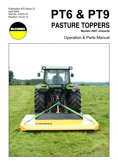
<strong>PT6</strong> & <strong>PT9</strong><br />
PASTURE TOPPERS<br />
Models 2007 onwards<br />
Operation & <strong>Parts</strong> <strong>Manual</strong>
IMPORTANT<br />
VERIFICATION OF WARRANTY REGISTRATION<br />
DEALER WARRANTY INFORMATION & REGISTRATION VERIFICATION<br />
It is imperative that the selling dealer registers this machine with <strong>McConnel</strong> Limited before<br />
delivery to the end user – failure to do so may affect the validity of the machine warranty.<br />
To register machines go to the <strong>McConnel</strong> Limited web site at www.mcconnel.com, log<br />
onto ‘Dealer Inside’ and select the ‘Machine Registration button’ which can be found in<br />
the Service Section of the site. Confirm to the customer that the machine has been<br />
registered in the section below.<br />
Should you experience any problems registering a machine in this manner please contact<br />
the <strong>McConnel</strong> Service Department on 01584 875848.<br />
Registration Verification<br />
Dealer Name: ……………………..…………………………………………………………….<br />
Dealer Address: …….………………………………………………………………………….<br />
Customer Name: ……………………..…………………………………………………………<br />
Date of Warranty Registration: ……/……/...…… Dealer Signature: ………………..……<br />
NOTE TO CUSTOMER / OWNER<br />
Please ensure that the above section above has been completed and signed by the selling<br />
dealer to verify that your machine has been registered with <strong>McConnel</strong> Limited.<br />
IMPORTANT: During the initial ‘bedding in’ period of a new machine it is the customer’s responsibility<br />
to regularly inspect all nuts, bolts and hose connections for tightness and re-tighten if required. New<br />
hydraulic connections occasionally weep small amounts of oil as the seals and joints settle in – where<br />
this occurs it can be cured by re-tightening the connection – refer to torque settings chart below. The<br />
tasks stated above should be performed on an hourly basis during the first day of work and at least<br />
daily thereafter as part of the machines general maintenance procedure.<br />
TORQUE SETTINGS FOR HYDRAULIC FITTINGS<br />
HYDRAULIC HOSE ENDS<br />
PORT ADAPTORS WITH BONDED SEALS<br />
BSP Setting Metric BSP Setting Metric<br />
1/4” 18 Nm 19 mm 1/4” 34 Nm 19 mm<br />
3/8” 31 Nm 22 mm 3/8” 47 Nm 22 mm<br />
1/2” 49 Nm 27 mm 1/2” 102 Nm 27 mm<br />
5/8” 60 Nm 30 mm 5/8” 122 Nm 30 mm<br />
3/4” 80 Nm 32 mm 3/4” 149 Nm 32 mm<br />
1” 125 Nm 41 mm 1” 203 Nm 41 mm<br />
1.1/4” 190 Nm 50 mm 1.1/4” 305 Nm 50 mm<br />
1.1/2” 250 Nm 55 mm 1.1/2” 305 Nm 55 mm<br />
2” 420 Nm 70 mm 2” 400 Nm 70 mm
WARRANTY POLICY<br />
WARRANTY REGISTRATION<br />
All machines must be registered, by the selling dealer with <strong>McConnel</strong> Ltd, before delivery to the end<br />
user. On receipt of the goods it is the buyer’s responsibility to check that the Verification of Warranty<br />
Registration in the <strong>Operator</strong>’s <strong>Manual</strong> has been completed by the selling dealer.<br />
1. LIMITED WARRANTIES<br />
1.01. All machines supplied by <strong>McConnel</strong> Limited are warranted to be free from defects in material<br />
and workmanship from the date of sale to the original purchaser for a period of 12 months,<br />
unless a different period is specified.<br />
1.02. All spare parts supplied by <strong>McConnel</strong> Limited are warranted to be free from defects in material<br />
and workmanship from the date of sale to the original purchaser for a period of 6 months.<br />
1.03. The manufacturer will replace or repair for the purchaser any part or parts found, upon<br />
examination at its factory, to be defective under normal use and service due to defects in<br />
material or workmanship. Returned parts must be complete and unexamined.<br />
1.04. This warranty does not apply to any part of the goods, which has been subjected to improper or<br />
abnormal use, negligence, alteration, modification, fitment of non-genuine parts, accident<br />
damage, or damage resulting from contact with overhead power lines, damage caused by<br />
foreign objects (e.g. stones, iron, material other than vegetation), failure due to lack of<br />
maintenance, use of incorrect oil or lubricants, contamination of the oil, or which has served its<br />
normal life. This warranty does not apply to any expendable items such as blades, flails, flap<br />
kits, skids, soil engaging parts, shields, guards, wear pads or pneumatic tyres.<br />
1.05. Temporary repairs and consequential loss - i.e. oil, downtime and associated parts are<br />
specifically excluded from the warranty.<br />
1.06. Warranty on hoses is limited to 12 months and does not include hoses which have suffered<br />
external damage. Only complete hoses may be returned under warranty, any which have been<br />
cut or repaired will be rejected.<br />
1.07. Machines must be repaired immediately a problem arises. Continued use of the machine after a<br />
problem has occurred can result in further component failures, for which <strong>McConnel</strong> Ltd cannot<br />
be held liable, and may have safety implications.<br />
1.08. Except as provided herein, no employee, agent, dealer or other person is authorised to give any<br />
warranties of any nature on behalf of <strong>McConnel</strong> Ltd.<br />
1.09. For machine warranty periods in excess of 12 months the following additional exclusions shall<br />
apply:<br />
1) Hoses, external seals, exposed pipes and hydraulic tank breathers.<br />
2) Filters.<br />
3) Rubber mountings.<br />
4) External electric wiring.<br />
1.10. All service work, particularly filter changes, must be carried out in accordance with the<br />
manufacturer’s service schedule. Failure to comply will invalidate the warranty. In the event of a<br />
claim, proof of the service work being carried out may be required.<br />
NB Warranty cover will be invalid if any non-genuine parts have been fitted or used. Use of<br />
non-genuine parts may seriously affect the machine’s performance and safety. <strong>McConnel</strong> Ltd<br />
cannot be held responsible for any failures or safety implications that arise due to the use of<br />
non-genuine parts.
2. REMEDIES AND PROCEDURES<br />
2.01. The warranty is not effective unless the Selling Dealer registers the machine, via the <strong>McConnel</strong><br />
web site and confirms the registration to the purchaser by completing the confirmation form in<br />
the operator’s manual.<br />
2.02. Any fault must be reported to an authorised <strong>McConnel</strong> dealer as soon as it occurs. Continued<br />
use of a machine, after a fault has occurred, can result in further component failure for which<br />
<strong>McConnel</strong> Ltd cannot be held liable.<br />
2.03. Repairs should be undertaken within two days of the failure. Claims submitted for repairs<br />
undertaken more than 2 weeks after a failure has occurred, or 2 days after the parts were<br />
supplied will be rejected, unless the delay has been authorised by <strong>McConnel</strong> Ltd.<br />
2.04. All claims must be submitted, by an authorised <strong>McConnel</strong> Service Dealer, within 30 days of the<br />
date of repair.<br />
2.05. Following examination of the claim and parts the manufacture will pay, at their discretion, for<br />
any valid claim the cost of any parts and an appropriate labour allowance if applicable.<br />
2.06. The submission of a claim is not a guarantee of payment.<br />
2.07. Any decision reached by <strong>McConnel</strong> Ltd. is final.<br />
3. LIMITATION OF LIABILITY<br />
3.01. The manufacturer disclaims any express (except as set forth herein) and implied warranties<br />
with respect to the goods including, but not limited to, merchantability and fitness for a particular<br />
purpose.<br />
3.02. The manufacturer makes no warranty as to the design, capability, capacity or suitability for use<br />
of the goods.<br />
3.03. Except as provided herein, the manufacturer shall have no liability or responsibility to the<br />
purchaser or any other person or entity with respect to any liability, loss, or damage caused or<br />
alleged to be caused directly or indirectly by the goods including, but not limited to, any indirect,<br />
special, consequential, or incidental damages resulting from the use or operation of the goods<br />
or any breach of this warranty. Notwithstanding the above limitations and warranties, the<br />
manufacturer’s liability hereunder for damages incurred by the purchaser or others shall not<br />
exceed the price of the goods.<br />
3.04. No action arising out of any claimed breach of this warranty or transactions under this warranty<br />
may be brought more than one (1) year after the cause of the action has occurred.<br />
4. MISCELLANEOUS<br />
4.01. The manufacturer may waive compliance with any of the terms of this limited warranty, but no<br />
waiver of any terms shall be deemed to be a waiver of any other term.<br />
4.02. If any provision of this limited warranty shall violate any applicable law and is held to be<br />
unenforceable, then the invalidity of such provision shall not invalidate any other provisions<br />
herein.<br />
4.03. Applicable law may provide rights and benefits to the purchaser in addition to those provided<br />
herein.
E.C MACHINERY DIRECTIVE<br />
98/37/EC<br />
CE DECLARATION OF CONFORMITY<br />
We hereby certify that the machinery stipulated below complies with all the relevant provisions<br />
of the EC Machinery Directive and the National Laws and Regulations adopting this Directive.<br />
Machine Description…. Mounted In-Line Toppers<br />
Make/ Model …………….<strong>PT6</strong>, PT8 & <strong>PT9</strong><br />
Manufacturer: LSM Engineering LTD<br />
Address: Ballymacken, Portlaoise, Co. Laois. (IRELAND)<br />
Is in conformity with the following other Directives and Standards;<br />
Directive 98/37/EC – Machinery Directive<br />
Directive 93/9 EEC – “CE Marking Directive”<br />
Harmonized Standards applied;<br />
EN 292 pt1:1991 - Safety of Machinery - Basic concepts, general principles for design<br />
EN 292 pt2:1991 - Safety of Machinery - Technical Principles and specifications<br />
EN 60204-1:1993 - Safety of Machinery - Electrical equipment of machines<br />
EN 1050:1996 - Safety of Machinery - Principle of Risk Assessment<br />
Signed Noel Graham<br />
Date January 2007<br />
Name Noel Graham<br />
Position Production Manager<br />
We reserve the right to make changes or improvements at any time without<br />
incurring any obligation to make such changes on products sold previously.
ROTARY MOWER INSPECTION AND MAINTENANCE<br />
A daily equipment inspection of the tractor and mower should be conducted before the<br />
equipment is used. You may use the inspection sheets to assist with these daily<br />
inspections. Any damaged or missing guards should be repaired or replaced before<br />
operating the mower. Failure to repair the damaged shield can result in objects being<br />
thrown from the mower and possibly hitting the operator or bystander.<br />
Inspect the Mower for Safe Operating Condition<br />
<br />
Make sure the driveline guards and shielding are in place and in good repair.<br />
Inspect the chain guards, flexible and/or solid defector thrown object shielding to<br />
assure that they are in place on the front and rear of the mower deck and in good<br />
repair. Repair or replace any damaged or missing thrown object shields.<br />
<br />
Remove all debris and cut material from the deck and around the gearboxes.<br />
Ensure the mower cutting height is set high enough to reduce the possibility of the<br />
mower blades contacting the ground. Actual height will be dependent on the ground<br />
conditions. Increase the height when working in rough or undulating conditions.<br />
Inspect for broken, chipped, bent, missing, or severely worn blades. Replace<br />
damaged blades before operating the mower. Ensure the blade retaining bolts and<br />
fasteners are secure and tight.<br />
<br />
Lubricate the driveline universal joints and telescoping members daily.<br />
Inspect the wheel lug bolt/nuts to assure that they are tight.<br />
If mower is equipped with pneumatic tires, make sure they have the required air<br />
pressure.<br />
Inspect for worn or damaged decals and safety instructions. Replace unreadable,<br />
damaged or missing safety decals.<br />
Follow the operator’s manual(s) inspection and maintenance instructions for<br />
lubricating parts, and keeping thrown object shielding, driveline guards, rotating<br />
parts shields, mower blades and decals in good repair.<br />
Inspect the Tractor for Safe Operating Condition:<br />
Inspect the controls, lights, SMVs (Slow Moving Vehicle sign), seat belts, and<br />
ROPS to assure that they are in place and in good working order.<br />
<br />
<br />
<br />
Be sure the tires, wheels, lug bolts/nuts are in good condition.<br />
Make sure the tractor brakes and steering are in proper operating condition.<br />
Follow the operator’s manual(s) inspection and maintenance procedures for<br />
keeping the tractor in good and safe condition before operating.<br />
The inspection sheet on the following page should be kept in this book as a record. A<br />
second sheet is included for you to cut out and photocopy or the inspection sheets can be<br />
down loaded from our web site at;<br />
http://www.mcconnel.com/support/aftersales/default.aspx?nav=After Sales
MOUNTED ROTARY MOWER PRE-OPERATION Inspection<br />
Mower ID ________________<br />
Date: _______________ Shift: _______________<br />
WARNING<br />
Before conducting the inspection, make sure the tractor engine is off, the key removed, all<br />
rotation has stopped and the tractor is in park with the parking brake engaged. Make sure<br />
the mower is resting on the ground or securely blocked up.<br />
Item<br />
The <strong>Operator</strong>’s <strong>Manual</strong> is in the Canister on the mower<br />
All Warning Decals are in place, clean and legible<br />
The mower decks are clear of cut grass and debris<br />
Chain Guards/Deflectors are in place & in good condition<br />
Driveline/Gearbox shields/guards are in good condition<br />
Driveline clutches are in good condition, not frozen<br />
Driveline telescoping members & u-joints are lubricated<br />
Driveline yokes are securely attached to tractor & mower<br />
Gearbox mounting bolts are tight<br />
Blade carrier retaining nut is tight<br />
Blades are not chipped, cracked, bent or worn out<br />
Blade bolts are tight<br />
Side skirts and skids are in good condition<br />
There are no holes or cracks in the machine deck<br />
Wheel nuts are tight<br />
All linkage mounting pins are securely fastened<br />
Lift height is restricted to prevent PTO hitting the deck<br />
Condition at<br />
start of shift<br />
Specific Comments if not O.K.<br />
<strong>Operator</strong>s Signature: ___________________________________________<br />
DO NOT OPERATE an UNSAFE TRACTOR or MOWER
TRACTOR PRE-OPERATION Inspection<br />
Power Arm ID ________________ Date: _______________ Shift: _______________<br />
WARNING Before conducting the inspection, make sure the tractor engine is off, the key is removed<br />
all rotation has stopped and the tractor is in park with the parking brake engaged. Any<br />
implement attached to the tractor is firmly on the ground.<br />
Item<br />
The flashing lights function properly.<br />
All lights are clean and working correctly<br />
All cab windows are clean and wipers working correctly<br />
The SMV sign, where required, is clean and visible.<br />
The tyres are in good condition with correct pressure.<br />
The wheel nuts are tight.<br />
The tractor brakes are in good condition.<br />
The steering linkage is in good condition.<br />
There are no visible oil leaks.<br />
The hydraulic controls function properly.<br />
The ROPS or ROPS cab is in good condition.<br />
The seatbelt is in place and in good condition.<br />
The 3-point hitch is in good condition.<br />
The drawbar/pick up hook is secure & in good condition<br />
The PTO master shield is in place.<br />
The engine oil level is full.<br />
The brake fluid level is full.<br />
The power steering fluid level is full.<br />
The fuel level is adequate.<br />
The engine coolant fluid level is full.<br />
The radiator & oil cooler are free of debris.<br />
The air filter is in good condition<br />
Condition at<br />
start of shift<br />
Specific Comments if not O.K.<br />
<strong>Operator</strong>s Signature: ___________________________________________<br />
DO NOT OPERATE an UNSAFE TRACTOR or MOWER
McCONNEL LIMITED<br />
Temeside Works<br />
Ludlow<br />
Shropshire SY8 1JL<br />
England<br />
Telephone: 01584 873131<br />
www.mcconnel.com
LIST OF CONTENTS<br />
Page No.<br />
Operation Section<br />
Introduction 1<br />
Features 2<br />
Specifications 3<br />
Safety Information 4<br />
Machine Decals 8<br />
Tractor Requirements 9<br />
Tractor Preparation 9<br />
Tractor Attachment 10<br />
Driveline Attachment 10<br />
Operation 12<br />
Cutting Speed 12<br />
Cutting Height 13<br />
Cutting Height Adjustment 13<br />
Starting and Stopping the Machine 14<br />
Worksite Checks and Procedures 14<br />
Detachment of the Machine 15<br />
Machine Storage 15<br />
Maintenance 16<br />
Lubrication Points 16<br />
Gearbox Lubrication 16<br />
Driveline Lubrication 17<br />
Driveline Shield Removal 18<br />
Blade Servicing 19<br />
Blade Sharpening 19<br />
Blade Removal 19<br />
Blade Carrier Removal 19<br />
Blade Carrier Installation 19<br />
General Troubleshooting 20<br />
PTO Shaft Troubleshooting 21<br />
Gearbox Troubleshooting 21<br />
<strong>Parts</strong> Section<br />
<strong>PT6</strong> Main Assembly 23<br />
<strong>PT6</strong> Drive Assembly 25<br />
<strong>PT6</strong> Blade Carrier Assembly 26<br />
<strong>PT9</strong> Main Assembly 27<br />
<strong>PT9</strong> Drive Assembly 29<br />
<strong>PT9</strong> Blade Carrier Assembly 30<br />
<strong>PT6</strong> Decal Kit 31<br />
<strong>PT9</strong> Decal Kit 32
INTRODUCTION<br />
McCONNEL PT SERIES MOWERS - Medium Duty Pasture Toppers<br />
Although designed primarily for the ‘topping’ of agri pastures the machines may also be used for<br />
‘topping’ sports grounds and local council areas. These machines should never be used for<br />
topping set-aside.<br />
Our machines are designed with care and built with quality materials by skilled workers. Proper<br />
assembly, maintenance and operating practices, as described in this manual, will help the<br />
owner/operator get years of satisfactory service from the machine.<br />
The purpose of this manual is to familiarise the owner/operator with the machine, and offer<br />
guidance to ensure it is operated both safely and correctly for its designated task.<br />
The parts section is designed to familiarise the owner/operator with replaceable parts on the<br />
machine - this section provides exploded assembly drawings of the machines components,<br />
illustrating each piece and identifying its part number.<br />
Careful use, timely service and the fitting of genuine parts will save extensive repairs and costly<br />
downtime. The operation and maintenance sections of the manual train the owner/operator how<br />
to work the machine correctly and attend to appropriate maintenance tasks. The trouble<br />
shooting guide helps diagnose difficulties with the machine and offer solutions to any problems.<br />
Safety is of primary importance to the owner/operator and to the manufacturer. The first section<br />
of this manual includes a list of safety messages that, if followed, will help protect the operator<br />
and bystanders from injury or death. Many of these messages will be repeated throughout the<br />
manual. The owner/operator/dealer should know these messages before attempting assembly<br />
or maintenance and to be aware of the hazards associated with the operation of this machine<br />
during assembly, use, and maintenance.<br />
1
FEATURES<br />
<strong>PT6</strong> Model<br />
• Three point linkage mounted.<br />
• Working width of 1.8m.<br />
• Cutting height from 24mm to 114mm.<br />
• 540-RPM PTO Shaft drive.<br />
• Shear pin protection.<br />
• Single rotor.<br />
• Semi-Offset cutting position.<br />
• Easy height adjustment.<br />
<strong>PT9</strong> Model<br />
• Three point linkage mounted.<br />
• Working width of 2.75m.<br />
• Cutting height from 24mm to 114mm.<br />
• 540-RPM PTO Shaft drive.<br />
• Shear pin protection.<br />
• Twin rotors.<br />
• Easy height adjustment.<br />
2
SPECIFICATIONS<br />
Description <strong>PT6</strong> Model <strong>PT9</strong> Model<br />
Cutting Width 1.8m (6ft.) 2.75m (9ft.)<br />
HP Requirement 35HP 45HP<br />
Weight 290kg 509kg<br />
Attachment 3-Point Linkage 3-Point Linkage<br />
Cutting Height 24 – 114mm 24 – 114mm<br />
Cutting capacity (Max. diameter of material to cut) 30mm 30mm<br />
Overall Width 2.0m 2.94m<br />
Overall Length 2.0m 1.89m<br />
PTO Speed 540RPM 540RPM<br />
Protection Shear Bolt Shear Bolt<br />
Blade Carriers 1 2<br />
No. of Rotors 1 2<br />
Blade Tip Speed 4500m/min 4620m/min<br />
Blade Overlap n/a 50mm<br />
Skids 2 2<br />
3
SAFETY<br />
There are obvious and potential hazards in the operation of this mower. REMEMBER! This<br />
machine may often be operated in brush of up to ½” (12mm) diameter. The blades of this<br />
mower can propel objects for a great distance at very high speeds. Serious injury or even death<br />
may occur unless care is taken to ensure the safety of the operator, bystanders or passersby in<br />
the area.<br />
KEEP CLEAR<br />
Before attempting to operate this machine the owner and the operator should read, understand<br />
and heed the following information. Serious injury or death may occur if the safety advice given<br />
here is ignored. In addition to this safety advice, good ‘common sense’ will go a long way<br />
towards avoiding hazardous situations and reduce the risk of danger.<br />
Rotary mowers are capable under adverse conditions of throwing objects great<br />
distances (100 yards or more) and causing serious injury or death.<br />
STOP MOWING IF PASSERSBY ARE WITHIN 100 YARDS (91 metres) unless:<br />
• Front and rear deflectors, chain guards or bands are fitted and are in good<br />
workable condition.<br />
• Mower sections or wings are running close to, and parallel to, the ground<br />
without exposed blades.<br />
• Passersby are outside the existing thrown-object zone.<br />
• All areas have been thoroughly inspected and foreign materials such as rocks,<br />
cans, glass and general ‘risk’ debris have been removed.<br />
NOTE: Where grass and weeds are high enough to obscure debris that could be struck by the<br />
blades, the area should be inspected and debris removed, mowed at an intermediate height,<br />
and re-inspected closely to remove any remaining debris and mowed again at the desired final<br />
height. (In addition to the safety aspect of this procedure it will also reduce wear and tear on the<br />
mower drivetrain, spread cut materials better, eliminate ‘streaking’ and make the final cut more<br />
uniform).<br />
All guards, bands, deflectors, driveline shields and gearbox shields should be<br />
used and maintained in good working condition at all times. They should be<br />
carefully inspected daily for missing or broken cable, chain links, shields or<br />
guards. Missing, broken or worn items must be replaced before attempting to use<br />
the machine to reduce the possibility of injury from thrown objects or<br />
entanglement.<br />
Extreme care should be taken when operating near loose objects such as gravel,<br />
rocks, wire and other debris. Foreign objects should be removed from the work<br />
site or avoided to prevent machine damage and/or bodily injury or even death.<br />
The rotating parts of this machine have been designed and tested for rugged use.<br />
However, they could fail upon impact with heavy solid objects such as steel<br />
guardrails and concrete abutments. Such impact could cause the broken objects<br />
to be thrown outward at very high velocities. To reduce the possibility of property<br />
damage, serious injuries, or even death, never allow the cutting blades to contact<br />
such objects.<br />
4
The operator and all support personnel should wear ‘hard hats’, ‘safety shoes’ and<br />
‘safety glasses’ at all times for protection from injury by falling objects and items<br />
thrown by the machine.<br />
Operate the mower only with a tractor equipped with an approved ‘roll over<br />
protection system (ROPS). Always wear your seat belt. Serious injury or even<br />
death could result from falling off the tractor – particularly during a turnover when<br />
the operator could be pinned under the ROPS or the tractor.<br />
Before leaving the tractor seat always engage the brake and/or set the tractor<br />
transmission in parking gear. Disengage the PTO, stop the engine, remove the<br />
key and wait for all moving parts to stop. Place the tractor shift lever into a low<br />
range or parking gear to prevent the tractor from rolling. Never mount or dismount<br />
a moving tractor. Operate the tractor controls from the tractor seat only.<br />
Many varied objects such as wire, cable, rope or chains can become entangled in<br />
the operating parts of mower head. These items could then swing outside the<br />
housing at greater velocities than the blades. Such a situation is extremely<br />
hazardous. Inspect the cutting area for any such objects and remove prior to<br />
mowing. Never allow the cutting blades to contact such items.<br />
Be particularly careful in transport. Turn curves or go up hills only at a low speed<br />
and at a gradual steering angle. Ensure that at least 20% of the tractor’s weight is<br />
on the front wheels to maintain safe steering. Slow down on rough or uneven<br />
surfaces.<br />
Ensure that all necessary signs are correctly displayed, and clearly visible, when<br />
working or transporting on or near a public highway. (Contact your Local Highway<br />
Authority to ensure you are fully conversant with your responsibilities on this<br />
subject). Use flashing warning lights when working or transporting on or near a<br />
public highway to indicate to other road users a potential hazard. Always abide by<br />
local traffic regulations.<br />
Ensure all moving parts of the machine are regularly inspected for wear and<br />
replaced with authorised service parts if an excessive amount of wear is present.<br />
Always use shear bolts recommended by <strong>McConnel</strong>.<br />
Ensure the machine is regularly inspected for loose fasteners, worn or broken<br />
parts and loose or leaky fittings. Ensure all pins are fitted with cotter pins and<br />
washers. Serious injury can result from failure to maintain this machine in good<br />
working order.<br />
5
Never leave the machine in the raised transport position – the machine could fall<br />
inadvertently and cause injury or death to anyone who might be under the<br />
machine.<br />
Never clean or adjust PTO driven equipment with the tractor engine running. Kill<br />
the engine and pocket the key before attempting any maintenance on the<br />
machine.<br />
Never allow riders on either the tractor or the mower - falling off can kill.<br />
Never allow children to operate, ride on, or come close to the mower or the tractor.<br />
Never work under the mower deck, framework or any raised component unless<br />
the mower has been securely supported and blocked using suitable substantial<br />
items to prevent sudden or inadvertent falling which could cause serious injury or<br />
even death.<br />
Never operate the tractor and mower until you have read, and fully understood,<br />
the operation manual and are conversant with all the safety instructions stated<br />
here. Ensure you read all safety messages found on both the tractor and the<br />
mower.<br />
Ensure you maintain all safety decals in good readable condition. If a decal should<br />
for any reason become illegible order a replacement immediately before permitting<br />
the machine to be used.<br />
Never run a tractor engine in a closed building without adequate ventilation. The<br />
exhaust fumes can be hazardous to your health.<br />
6
Ensure that a PTO shield is installed when using PTO-driven equipment and<br />
always replace the PTO shield if damaged.<br />
PROLONGED EXPOSURE TO LOUD NOISE MAY CAUSE PERMANENT<br />
HEARING LOSS! Tractors with or without mowers attached can often be noisy<br />
enough to cause permanent or partial hearing loss. We recommend that hearing<br />
protection be worn at all times when the noise level experienced in the operator’s<br />
position exceeds 80db. Noise in excess of 85db on a long-term basis can cause<br />
permanent total hearing loss. Where the tractor is fitted with a ‘quiet cab’ it is<br />
recommended that the windows are kept closed at all times whilst operating this<br />
machine.<br />
In addition to the safety messages stated here the machine is fitted with warning decals that are<br />
designed to bring to the attention of the operator the potential dangers that exist whilst using the<br />
machine. However, these cannot replace correct proper training and total awareness of all the<br />
dangers involved in using a machine of this type, and the nature of the work it does. BE ALERT,<br />
PAY ATTENTION – SOMEONE’S LIFE MAY BE AT STAKE!<br />
WHEN THIS SYMBOL IS DISPLAYED:<br />
• BE ALERT<br />
• PAY ATTENTION<br />
• SOMEONE’S LIFE IS AT STAKE<br />
7
MACHINE DECALS<br />
1. Part Number 09.811.04<br />
2. Part Number D137<br />
4. Part Number D132<br />
3. Part Number D138<br />
5. Part Number 09.821.29 6. Part Number 09.821.30<br />
8. Part Number 09.810.02<br />
7. Part Number 09.821.34<br />
9. Part Number 41.094.05 11. Part Number 1290527<br />
12. Part Number 1290832 Part Number 1290833<br />
8
TRACTOR REQUIREMENTS<br />
The PT mowers will attach to most tractors with Cat. II & Cat. II Quick Hitch.<br />
The machines require a tractor with 540RPM PTO and a minimum 35HP for <strong>PT6</strong> models and<br />
45HP for <strong>PT9</strong> models.<br />
Adequate front-end weights should be fitted - at least 20% of the tractor’s weight must be on the<br />
front tyres when the mower is lifted to provide adequate traction for safe steering under good<br />
conditions.<br />
TRACTOR PREPARATION<br />
Ballast<br />
Do not operate with less than 20% of the tractor’s gross un-ballasted mass on the<br />
front wheels with the mower in the transport position.<br />
Wheel Spacing<br />
The wheel spacing on the tractor should be increased when working on inclines or rough<br />
ground to reduce the possibility of tipping.<br />
Stabiliser Bars or Sway Blocks<br />
Use stabiliser bars or sway blocks to prevent side sway of the mower.<br />
Draft Links<br />
The linkage to the lower draft links should be set in the ‘float’ position, allowing the unit to follow<br />
the contour of the terrain.<br />
Tractor Drawbar<br />
Shorten or remove the tractor drawbar so it does not interfere with the up and down movements<br />
of the mower.<br />
Do not get, or allow others, between the tractor and the mower when the engine is<br />
running. Always ‘kill’ the engine, apply handbrake, engage tractor in gear, and<br />
pocket the key before attempting to work between tractor and machine.<br />
9
TRACTOR ATTACHMENT<br />
• Back the tractor up to the mower so that the lower draft arms are in alignment with the<br />
mower lower lift pins.<br />
• Stop engine, lock the brakes or place the tractor in park.<br />
• Connect the tractor and stabiliser bars to the lower lift pins.<br />
• Adjust the top link so it will pin to the top holes in the A-frame.<br />
• Attach webbing support strap at its mid-point through the A-frame shackle and attach ends<br />
to each rear corner shackle.<br />
DRIVELINE ATTACHMENT<br />
Before starting assembly of the driveline ensure that all paint, dirt and grease are removed from<br />
the gearbox shaft. To ease assembly apply a light coat of grease to splines prior to fitting.<br />
WARNING<br />
Do not assemble a driveline without a shield.<br />
Driveline Length Check Procedure<br />
A loose shaft could slip off and result in personal injury or damage to the mower.<br />
When attaching PTO yoke to tractor PTO shaft, it is important that the springactivated<br />
locking collar slides freely and locking balls are seated in the groove on<br />
the PTO shaft.<br />
Before operating the mower, check to ensure the driveline will not ‘bottom out’ or<br />
become disengaged. ALWAYS use Shear Bolts recommended by <strong>McConnel</strong>.<br />
• Set parking brake, kill<br />
engine, remove and pocket<br />
the key.<br />
• Disengage the driveline<br />
from the tractor PTO shaft.<br />
Driveline in maximum compressed position<br />
1/8" (3mm)<br />
• Slide the driveline together<br />
until it ‘bottoms out’ solidly.<br />
• Apply coloured tape to the<br />
inner shield ⅛” (3mm) from<br />
the end of the outer shield<br />
(see diagram opposite).<br />
Coloured Tape<br />
10
• Re-attach the driveline to the PTO shaft; ensuring balls are correctly seated in the groove on<br />
shaft.<br />
• Raise mower to full transport height or until driveline just touches deck at front. If distance<br />
between coloured tape and outer shield is 1⅝” (40mm) or less, drive tubes should be<br />
shortened (see diagram below).<br />
• Always maintain 1⅝” (40mm) clearance when operating in the shortest working position.<br />
Shorten inner and outer guard tubes equally. Shorten inner and outer sliding profiles by the<br />
same amount that the shield tubes were shortened. Round off all sharp edges and remove<br />
burrs. Grease sliding profiles (see diagram below).<br />
• Lower mower to lowest position possible. Check distance from coloured tape to end of outer<br />
shield tube. Driveline tube engagement must always exceed 12” (300mm). If not consult<br />
your dealer to obtain a longer driveline.<br />
11
OPERATION<br />
The safe operation of this machine is the responsibility of the operator who should be familiar<br />
with the machine, the tractor, and all safety practices associated with this type of mower, before<br />
attempting to start operation.<br />
Before operating your rotary mower ensure it is properly lubricated and thoroughly inspected.<br />
The time and effort required to regularly lubricate and maintain the mower is minimal, but<br />
necessary, to provide long life and trouble free operation of your machine – refer to<br />
maintenance section for details.<br />
These mowers are designed primarily for medium duty grassland topping, the <strong>PT6</strong> model is<br />
equipped with a single set of updraft blades mounted on a rotating blade carrier; the cutting<br />
direction of which is clockwise when viewed from below. The <strong>PT9</strong> model is equipped with two<br />
sets of updraft blades mounted on blade carriers rotating in opposing directions; the blade<br />
carriers are timed at 90° to each other – see diagram below.<br />
FRONT<br />
Anti-Clockwise Cutting Direction<br />
Clockwise Cutting Direction<br />
<strong>PT9</strong> Cutting Blades - Rotation & Timing Diagram (viewed from below).<br />
Cutting Speed<br />
Correct ground speed for cutting will depend upon the height, type and density of the material<br />
being cut, but normally it will be in the range of 2–5 mph (3-8 km/h). Tall dense material should<br />
be cut at a low speed while thin medium height material can be cut at a faster ground speed;<br />
with practice and experience the operator will be able to judge conditions and materials and<br />
select the optimum forward speed to achieve efficient mowing.<br />
Always operate the PTO at the recommended RPM when cutting; this is necessary to maintain<br />
the correct blade speed to produce a clean cut.<br />
Under certain conditions tractor tyres may roll some grasses down and prevent them from being<br />
cut at the same height as the surrounding area. When this occurs, reduce the tractor ground<br />
speed, but maintain PTO rpm. The lower speed will permit grasses to, at least, partially rebound<br />
and be cut. Taking a partial cut and/or reversing the direction of travel may also produce a<br />
cleaner cut.<br />
Always stop mowing when people are passing by and keep bystanders at a safe distance away<br />
from risk of danger.<br />
12
Cutting Height<br />
The cutting height of the mower is determined by the position at which the side skids are<br />
mounted on the machine – height adjustment is made by selecting higher or lower pairs of holes<br />
in the skids through which to attach the mounting bolts.<br />
It is advisable to increase topping height by an extra 25mm (1”) to avoid ‘grounding’ of the<br />
machine when cutting on uneven terrain.<br />
Each side skid is fixed into position with 4 nuts and bolts (2 front & 2 rear) and may be mounted<br />
at four different cutting heights from 17.7mm to 107.7mm.<br />
The diagram below shows the skid height adjustment positions where ‘A’ is the minimum cutting<br />
height and ‘D’ is the maximum.<br />
Cutting Heights<br />
A = 24.2mm (0.95”)<br />
B = 54.2mm (2.13”)<br />
C = 84.2mm (3.31”)<br />
D = 114.2mm (4.5”)<br />
Cutting Height Adjustment<br />
WARNING: As adjustment to the cutting height requires initial removal of the skids it is vital that<br />
both machine and tractor are switched off, the unit parked on firm level ground and safely<br />
supported or ‘blocked’ before attempting this procedure – ensure when refitting the skids that<br />
matching sets of holes front and back and side to side are selected so that the mower remains<br />
parallel to the ground.<br />
IMPORTANT: To avoid damage to the machine re-torque all bolts after the first 10 hours of<br />
initial operation – thereafter all bolts should be checked at regular intervals and re-tightened if<br />
required. The required torque setting for the blade carrier retaining nut on the gearbox lower<br />
shaft is 450 ft. lbs (610 Nm).<br />
13
Starting & Stopping the Machine<br />
Power for operating the Mower is supplied from tractor PTO. Refer to your Tractor <strong>Manual</strong> for<br />
instructions regarding engaging and disengaging of the PTO.<br />
ALWAYS engage the PTO at low engine rpm and gradually build up the speed; sudden starts at<br />
high RPM can cause the shear bolt to shear.<br />
ALWAYS operate at the recommended PTO speed.<br />
LEARN how to stop the Tractor and Mower quickly and safely in case of emergency.<br />
IMPORTANT: Stop the Mower and Tractor immediately upon striking an obstruction. Inspect the<br />
Mower for damage and repair before resuming operation. DO NOT DISENGAGE PTO WHEN<br />
ENGINE IS AT FULL PTO RPM – always idle engine before disengaging the PTO.<br />
Avoid personal injury. When attempting to stop a tractor that does not have live<br />
PTO, the momentum created by the blade carrier of a rotary mower can cause the<br />
tractor to be pushed forward. DO NOT operate this Mower unless tractor has live or<br />
independent PTO.<br />
To commence operation, reduce engine speed and engage the tractor PTO. Before starting to<br />
cut, gradually increase the engine speed to develop full PTO speed.<br />
Enter the area to be cut with the mower operating at PTO speed and, if it becomes necessary to<br />
temporarily regulate engine speed during operation, increase or decrease the throttle gradually.<br />
Work Site Checks & Procedures<br />
To avoid risk of personal injury or damage to the machine it is good practice to<br />
inspect the work area prior to operation – take time to pick up rocks, bottles, wire<br />
etc. and any other hazardous debris you may find in order to avoid them coming<br />
into contact with the working machine. The blade tip speed of these machines is<br />
well in excess of 4000m/min and therefore has the potential to hit movable objects<br />
long distances at high speed.<br />
Note the position of non-removable hazards and dangers so that they can be<br />
avoided during operation.<br />
Extremely tall grass should be cut twice. Raise the Mower and cut twice to the desired height.<br />
Cut the second time to the desired height at 90 degrees to the first pass.<br />
Remember that sharp blades will produce a cleaner cut and will use less power.<br />
Before cutting, analyze the area to determine the best cutting procedure. Consider the height<br />
and type of material as well as the terrain type i.e. hilly, level, or rough.<br />
14
DETACHMENT OF THE MACHINE<br />
• Lower the Mower to the ground and park the Tractor with brakes on, kill the engine, remove<br />
and pocket the key.<br />
• Wait until the PTO has stopped rotating before dismounting the Tractor.<br />
• Disconnect the Driveline from the Tractor PTO.<br />
• Disconnect the Top Link and the Lower Lift Links from the Mower.<br />
• Always reinstall the Master Shield over the Tractor PTO shaft - this shield should always<br />
remain in place and should only be removed to enable the connection or disconnection of<br />
the Driveline.<br />
Removal of the machine should always be performed on a firm level site.<br />
Machine Storage<br />
Inspect the machine prior to storage for any signs of wear or damage. Repair or replace any<br />
parts that are worn or damaged in order that the machine is prepared and ready for work when<br />
next needed. Storage of the machine should ideally be in a clean dry environment safely sited<br />
where it is protected from the elements. Clean and lubricate the machine prior to storage.<br />
IMPORTANT:<br />
This machine must only be used to perform tasks for which it was designed; never use this machine for<br />
anything other than its designated task or for tasks beyond its capability.<br />
Warranty for breakdowns will not be allowed if the machine has been misused in any way – this includes;<br />
overloading by the operator, operating without due care, use of non-genuine parts, lack of daily and/or<br />
regular maintenance, failure to remove, observe, or avoid obstacles whilst working. This machine will not<br />
be covered by warranty if ‘hired out’ or operated by third parties.<br />
15
MAINTENANCE<br />
Always disengage the PTO before raising the Mower for transporting or making<br />
adjustments.<br />
Do not allow excess grease to collect on or around the machines parts, particularly<br />
when operating in sandy areas.<br />
Lubrication Points<br />
The illustration below shows the location of the machines lubrication points and the frequency at<br />
which these points should be lubricated under normal working conditions, severe or unusual<br />
conditions may require more frequent lubrication. Use SAE multi-purpose lithium type grease for<br />
all greasing locations indicated ensuring the fitting is thoroughly cleaned before applying<br />
lubricant to avoid contamination by dirt or grit.<br />
Lubrication Points<br />
1. U-Joints<br />
Every 8 hours of work<br />
See driveline lubrication.<br />
2. Telescoping<br />
Every 16 hours of work<br />
See driveline lubrication.<br />
3. Gearbox<br />
Check level daily<br />
See gearbox lubrication.<br />
Gearbox Lubrication<br />
The gearbox will be filled with lubricant to the test plug level<br />
prior to shipment, however, as a precaution you should check<br />
the oil level at the test plug before operating the machine and<br />
frequently thereafter. Check daily during normal use.<br />
Gearbox Plug Locations<br />
Filler Plug<br />
The gearbox should not require additional lubricant unless the<br />
box is cracked or a seal is leaking. It is recommended that the<br />
oil level plug be removed every 8 to 10 hours of normal<br />
operation and oil added until it runs out of the Test Plug hole.<br />
The test plug is located on the rear of the gearbox and the filler<br />
plug is located on the top of the gearbox.<br />
Test Plug<br />
16
Recommended lubricants for the Gearbox are: Exxon – Spartan EP220, Mobil HD 80W90, or<br />
equivalent. Required lubricant is a SAE 90 or SAE 80W90 with EP additives for extreme<br />
pressure and temperature with a API-GI-5 Service rating.<br />
NOTE: Overfilling the gearbox will result in pressure build up and cause oil seals to leak.<br />
ATTENTION: If gearbox suddenly starts making an unusual noise the machine must be stopped<br />
immediately and the gearbox checked for leaks and refilled if required.<br />
Driveline Lubrication<br />
Grease Fittings are located on the cross assembly of each U-Joint and on the telescoping<br />
tubes.<br />
Grease the U-Joint after every 8 hours of use. Do not force grease through the needle cup<br />
assemblies.<br />
Grease the telescoping tubes after every 16 hours of use.<br />
On some PTO to hitch connections it may be necessary to cut a hole in the shields to facilitate<br />
alignment of the grease fittings for lubrication. Lubricate the shield bearings every 8 hours - see<br />
diagram below and refer to the information sheet shipped with the PTO shaft.<br />
Driveline Lubrication Points and Frequency<br />
17
Driveline Shield Removal<br />
The driveline integral shields should not become dented or otherwise damaged. The integral<br />
shield assembly has a nylon bearing at each end, which should turn freely, and will require<br />
lubricating after every 8 hours of use. To remove the integral shields for replacement or repair,<br />
turn the three nylon bolts through a ¼ turn in the shield slots of the cone and tube and remove<br />
them. Slip the shield cone assembly off the inner section of the driveline and install the new or<br />
repaired shield on the driveline. Place the split nylon bearing over the driveline housing against<br />
the yoke and in the bearing groove. Install shield over the housing so the nylon bearing fits into<br />
the shield bearing retainer. Align a slot in the shield cone with one of the slots in the shield. Put<br />
one of the nylon bolts back in through the aligned slot and turn until it is perpendicular to the<br />
slots. Replace the other two nylon bolts.<br />
Ensure that the driveline integral shields are free to telescope and rotate around<br />
the driveline without binding.<br />
When attaching PTO yoke to tractor PTO shaft, it is important that the springactivated<br />
locking collar slides freely and that the locking balls are seated in the<br />
groove on the PTO shaft. A loose shaft could slip off and result in personal injury<br />
or damage to your machine.<br />
Blade Servicing<br />
Blades should always be inspected prior to work each time you use the Mower to ensure they<br />
are in good working condition and correctly installed. Replace any Blade that is bent,<br />
excessively nicked, worn or otherwise damaged. Small nicks can be ground out when<br />
sharpening. If a Blade requires replacing, it is recommended that they be replaced in pairs in<br />
order to maintain balance.<br />
IMPORTANT: When sharpening blades, grind each blade by the same amount to maintain<br />
balance. The difference in blade weights should not exceed 1 ounce (28gms). Unbalanced<br />
blades will cause excessive vibration, which can damage gearbox bearings. Vibration may also<br />
cause structural cracks in the Mower housing.<br />
Use only Original Equipment Blades on this Mower. They are made of special-heat<br />
treated alloy steel. Substitute Blades may not meet the specifications required for<br />
this Mower and may fail in a hazardous manner that could cause injury.<br />
18
Blade Sharpening<br />
Always sharpen both blades at the same time to<br />
maintain balance. Follow the original sharpening<br />
pattern (see diagram below) and always<br />
sharpen blades by grinding. DO NOT heat and<br />
‘pound out’ edge or sharpen the blade to a razor<br />
edge, but leave a 1/16” (1.6mm) blunt edge. Do<br />
not sharpen the back side of the blade.<br />
Blade Maintenance<br />
Avoid personal injury. Always block the Mower up to prevent it from falling when<br />
servicing the blades and/or carrier.<br />
Blade Removal<br />
To remove blades for sharpening or replacement; remove the cover plate on the deck of the<br />
mower near the gearbox and remove the locknut from the blade bolt. NOTE: Inspect locknut<br />
after removal and replace if threads are damaged. Always replace locknut when replacing blade<br />
bolt.<br />
When installing or replacing blades ALWAYS check the blade bolt pivot diameter for wear and<br />
replace if it is worn more than ¼” (6mm) at any point. Install blade bolts with ‘unworn’ portion of<br />
blade bearing area towards centre of carrier. Tighten locknut to 350 ft-lb. (475Nm).<br />
Avoid personal injury. Blade and/or blade carrier removal should only be done with<br />
the tractor engine shut off, key removed, in neutral, parking brake on, with the PTO<br />
disengaged and the mower securely blocked in the raised position.<br />
Blade Carrier Removal<br />
Remove cotter pin and loosen locknut on gearbox shaft; do not remove the nut until the blade<br />
carrier is loosened. Use a suitable 2-jaw gear puller to draw the carrier off the tapered gearbox<br />
shaft. If gear puller is not available a long bar can be utilized by inserting it through the blade<br />
bolt access hole with the end against rotor bar. Strike opposite end of bar with a sledgehammer.<br />
Rotate blade carrier through 180° and repeat the process.<br />
Blade Carrier Installation<br />
Clean the splines on both the blade carrier and the output shaft. Position carrier on the gearbox<br />
output shaft and install special washer and nut.<br />
Tighten nut holding blade carrier to minimum 450 ft-lb. (610Nm) strike the carrier near the hub<br />
several times with a heavy hammer to seat the hub. Use a suitable spacer over the nut to<br />
prevent damage to the nut and its thread. Retighten the nut to 450 ft-lb. (610Nm). Install cotter<br />
pin and spread its ends.<br />
IMPORTANT: Always rechecks gearbox output shaft slotted blade carrier retaining nut torque<br />
after a few hours of operation.<br />
Avoid personal injury. Do not attempt to work under the mower without suitable<br />
support blocks under the frame.<br />
19
TROUBLESHOOTING - General<br />
PROBLEM POSSIBLE CAUSE REMEDY<br />
Not cutting cleanly<br />
Blades dull.<br />
Sharpen or replace blades.<br />
Breaking blade bolts<br />
Cutting too high<br />
Machine vibration<br />
Mower windrowing<br />
Rapid blade wear<br />
Blade bolts working loose<br />
Blade rotation incorrect.<br />
Using straight blades.<br />
Carrier rpm too low.<br />
Mower not levelled.<br />
Tyres flattening grass.<br />
Ground speed too fast.<br />
Blades locked back.<br />
Blades riding up due to<br />
Blade bolt wear.<br />
Blades bent up.<br />
Operating with loose blade<br />
bolts.<br />
Worn blade bolt.<br />
Blades bent up.<br />
Blade carrier bent.<br />
Blades on upside down.<br />
Blade locked back.<br />
Drivelines not phased.<br />
Blade broken.<br />
Blade carrier bent.<br />
Blade hub not properly<br />
seated on shaft.<br />
New blade matched with<br />
worn blade.<br />
Cutting heavy material.<br />
Cutting in sandy or rocky<br />
conditions.<br />
Blades too soft.<br />
Bolts not tightened.<br />
Bolt hole elongated or<br />
oversized.<br />
Locknut worn out.<br />
20<br />
Use correct blade carrier.<br />
Use fan blades in grass.<br />
Increase PTO to recommended rpm<br />
Adjust machine level.<br />
Increase tyre spread to 90” (2.25m).<br />
Reduce ground speed.<br />
Free blades.<br />
Replace blade bolts.<br />
Replace blades.<br />
Tighten blade bolts to 350 ft lb. (475 Nm) –<br />
R/H threads.<br />
Replace bolt.<br />
Replace blades.<br />
Straighten or replace blade carrier.<br />
Turn blades right side up and tighten.<br />
Loosen locked blade.<br />
Replace driveline.<br />
Replace blades in sets.<br />
Repair or replace carrier.<br />
Remove hub, check for wear and replace<br />
or seat properly - tighten hub bolts to 450<br />
ft lb. (610Nm).<br />
Replace blades in sets.<br />
Raise mower and reduce groundspeed.<br />
Increase cutting height.<br />
Replace blades with hardened high-quality<br />
blades from the manufacturer.<br />
Tighten bolts to 350 ft lb. (475 Nm.)<br />
Replace blade carrier.<br />
Replace locknut.
TROUBLESHOOTING – PTO Shafts<br />
PROBLEM POSSIBLE CAUSE REMEDY<br />
Broken cross or cups Load too high for joint. Use protective device with joint.<br />
Check joint angles and phasing.<br />
Slow down or raise mower.<br />
End galling of cross and<br />
cups<br />
Speed too high during<br />
turns.<br />
Reduce PTO speed.<br />
Needle rollers have Load too high for joint. Check for small joint angles.<br />
brinelled into cup and<br />
Check joint angles and phasing.<br />
cross<br />
Shaft or tube twisted Over-loaded. Replace part and then slow down or raise<br />
mower.<br />
Use protective device.<br />
Tube broken in welded<br />
seam<br />
Over-loaded.<br />
Replace part.<br />
Yoke broken at ear tip Over-loaded. Replace part.<br />
Driveline integral shields<br />
rattling or not turning<br />
freely<br />
Integral shields deformed.<br />
Nylon bearing worn.<br />
TROUBLESHOOTING – Gearboxes<br />
Replace shield.<br />
Replace nylon bearing.<br />
PROBLEM POSSIBLE CAUSE REMEDY<br />
Noisy gearbox<br />
Improper backlash.<br />
Rough gears.<br />
Worn bearings.<br />
Refer to your dealer.<br />
Run in or change gears.<br />
Replace bearings.<br />
Oil blowing out of vent<br />
plug<br />
Gearbox leaking<br />
Flat bottomed Vent Plug or<br />
shallow cavity Plug.<br />
Oil level too high.<br />
Damaged oil seal.<br />
No oil seal.<br />
Oil too light.<br />
Bent shaft.<br />
Oil seal race rough.<br />
Oil seal installed<br />
incorrectly.<br />
Oil seal not sealing in<br />
housing.<br />
Bearings loose.<br />
Vent plug stopped up.<br />
Oil level too high.<br />
Gasket damaged.<br />
Bolts loose.<br />
Replace with proper vent plug, cavity in oil<br />
plug should be approximately ⅝” (16mm).<br />
Lower oil level to plug.<br />
Replace seal.<br />
Install oil seal.<br />
Use EP90.<br />
Replace oil seal and shaft.<br />
Replace shaft or repair race.<br />
Replace seal.<br />
Replace seal or use sealant.<br />
Adjust bearings.<br />
Open vent plug.<br />
Drain oil to correct level.<br />
Replace gasket.<br />
Tighten bolts.<br />
21
PARTS MANUAL<br />
<strong>PT6</strong> & <strong>PT9</strong><br />
PASTURE TOPPERS<br />
22
<strong>PT6</strong> TOPPER ASSEMBLY<br />
Module(s): 1096730<br />
McCONNEL<br />
23
<strong>PT6</strong> TOPPER ASSEMBLY<br />
Module(s): 1096730<br />
McCONNEL<br />
REF. QTY. PART No. DESCRIPTION<br />
1096730 <strong>PT6</strong> TOPPER ASSEMBLY<br />
1 1 1096270 MAIN BODY<br />
2 2 1096267 ADJUSTABLE SKID<br />
3 1 1096330 BLADE CARRIER ASSEMBLY<br />
4 1 1096268 A-FRAME<br />
5 1 1096254 BOW SHACKLE<br />
6 2 1096266 SLING<br />
7 4 0431217 LYNCH PIN<br />
8 2 1096322 LOWER LINK PIN - CAT I/II<br />
9 1 1096331 DRIVE ASSEMBLY (COMPLETE)<br />
10 2 ELA0027 D SHACKLE<br />
11 8 9213066 BOLT<br />
12 8 9143006 LOCKNUT<br />
13 8 9100106 WASHER<br />
14 6 9213107 BOLT<br />
15 6 9143007 LOCKNUT<br />
24
<strong>PT6</strong> DRIVE ASSEMBLY<br />
Module(s): 1096331<br />
McCONNEL<br />
REF. QTY. PART No. DESCRIPTION<br />
1096331 <strong>PT6</strong> DRIVE ASSEMBLY<br />
1 1 21040.05 DRIVE SHAFT c/w SHEARBOLT<br />
2 1 21238.01 CONE<br />
3 1 1096300 GEARBOX<br />
4 4 1061090 BOLT<br />
5 1 9200063 SHEAR BOLT<br />
6 1 9113004 NUT<br />
25
<strong>PT6</strong> BLADE CARRIER ASSEMBLY<br />
Module(s): 1096330<br />
McCONNEL<br />
REF. QTY. PART No. DESCRIPTION<br />
1096330 <strong>PT6</strong> BLADE CARRIER ASSEMBLY<br />
1 1 1096302 BLADE CARRIER<br />
2 2 1096305 BUSH<br />
3 2 1096304 BLADE<br />
4 2 1096306 BOLT<br />
5 2 1096333 LOCKNUT<br />
26
<strong>PT9</strong> TOPPER ASSEMBLY<br />
Module(s): 1096731<br />
McCONNEL<br />
27
<strong>PT9</strong> TOPPER ASSEMBLY<br />
Module(s): 1096731<br />
McCONNEL<br />
REF. QTY. PART No. DESCRIPTION<br />
1096731 <strong>PT9</strong> TOPPER ASSEMBLY<br />
1 1 1096251 MAIN BODY<br />
2 2 1096252 ADJUSTABLE SKID<br />
3 2 1096334 BLADE CARRIER ASSEMBLY<br />
4 1 1096253 A-FRAME<br />
5 1 1096254 BOW SHACKLE<br />
6 2 1096314 SLING<br />
7 2 0431217 LYNCH PIN<br />
8 2 1096315 LOWER LINK PIN - CAT II<br />
9 1 1096335 DRIVE ASSEMBLY (COMPLETE)<br />
10 2 ELA0027 D SHACKLE<br />
11 1 1096255 MAIN GUARD<br />
12 1 1096336 RUBBER STOP<br />
13 8 9213066 BOLT<br />
14 8 9143006 LOCKNUT<br />
15 8 9100106 WASHER<br />
16 2 9213108 BOLT<br />
17 2 9143008 LOCKNUT<br />
18 2 9213065 BOLT<br />
19 2 9100105 WASHER<br />
20 1 9143005 LOCKNUT<br />
21 3 9213064 BOLT<br />
22 3 9100104 WASHER<br />
23 3 9143004 LOCKNUT<br />
28
<strong>PT9</strong> DRIVE ASSEMBLY<br />
Module(s): 1096335<br />
McCONNEL<br />
REF. QTY. PART No. DESCRIPTION<br />
1096335 <strong>PT9</strong> DRIVE ASSEMBLY<br />
1 1 21040.06 DRIVE SHAFT (OVER RUN) c/w SHEARBOLT<br />
2 1 1096337 CONE EXTENSION<br />
3 1 21238.01 CONE<br />
4 1 21459.01 T GEARBOX<br />
5 2 21457.02 FLEXIBLE DRIVE SHAFT<br />
6 2 1096287 RUBBER COUPLER<br />
7 2 1096338 STAR DRIVE SHAFT<br />
8 2 21459.02 RIGHT ANGLE GEARBOX<br />
9 2 1096334 BLADE CARRIER ASSEMBLY (2007)<br />
10 4 9213158 BOLT<br />
11 4 9143008 LOCKNUT<br />
12 4 9213066 BOLT<br />
13 16 9143006 LOCKNUT<br />
14 4 9100106 WASHER<br />
15 12 9213166 BOLT<br />
16 8 9213107 BOLT<br />
17 8 9143007 LOCKNUT<br />
1096339 RETRO-FIT KIT (2007)<br />
29
<strong>PT9</strong> BLADE CARRIER ASSEMBLY<br />
Module(s): 1096334<br />
McCONNEL<br />
REF. QTY. PART No. DESCRIPTION<br />
1096334 <strong>PT9</strong> BLADE CARRIER ASSEMBLY<br />
1 2 1096325 BLADE CARRIER<br />
2 4 1096303 BUSH<br />
3 4 1096304 BLADE<br />
4 4 9213168 BOLT<br />
5 4 1096333 LOCKNUT<br />
30
<strong>PT9</strong> OUTER GEARBOX ASSEMBLY<br />
Module(s): 21459.02<br />
McCONNEL<br />
31
<strong>PT9</strong> OUTER GEARBOX ASSEMBLY<br />
Module(s): 21459.02<br />
McCONNEL<br />
REF. QTY. PART No. DESCRIPTION<br />
21459.02 GEARBOX ASSEMBLY<br />
1 1 21459.23 CROWN GEAR<br />
2 1 21459.41 CASING<br />
3 1 21459.24 INPUT SHAFT<br />
4 1 21459.26 PINION<br />
5 1 21459.27 SPACER<br />
6 1 21459.25 OIL CAP<br />
7 1 21459.42 PROTECTIVE WASHER<br />
8 1 21459.28 BALL BEARING<br />
9 1 21459.29 BALL BEARING<br />
10 2 21459.30 BALL BEARING<br />
11 1 21459.45 CASTLE NUT<br />
12 1 21459.46 BOLT WASHER<br />
13 1 21459.99 PARALLEL KEY<br />
14 4 21459.47 BOLT<br />
15 1 21459.44 SNAP RING<br />
16 1 21459.32 SNAP RING<br />
17 1 21459.33 SNAP RING<br />
18 2 21459.39 PLUG<br />
19 1 21459.22 DUST LIP<br />
20 1 21459.34 OIL SEAL<br />
21 1 21459.48 COVER<br />
22 2 21459.35 SHIM KIT<br />
23 1 21459.36 SNAP RING<br />
24 1 21459.37 SHIM KIT<br />
25 1 21459.49 NAME PLATE<br />
26 1 21459.40 SHIM KIT<br />
27 1 21459.04 SNAP RING<br />
28 1 21459.31A BUSH<br />
29 1 21459.66 COTTER PIN<br />
32
<strong>PT6</strong> DECAL KIT<br />
Module(s): 1096710K<br />
McCONNEL<br />
REF. QTY. PART No. DESCRIPTION<br />
1096710K DECAL KIT - <strong>PT6</strong><br />
1 1 41.094.05 SERIAL No. PLATE<br />
2 1 09.811.04 DECAL - 540 MAX ACW<br />
3 1 09.821.29 DECAL - COMBINED EURODECAL<br />
4 1 09.821.30 DECAL - EURODECAL ROTARY<br />
5 1 09.821.34 DECAL - COMBINED EURODECAL<br />
6 4 7103230 POP RIVET<br />
7 1 1290527 DECAL - MCCONNEL<br />
8 2 1290832 DECAL - <strong>PT6</strong><br />
33
<strong>PT9</strong> DECAL KIT<br />
Module(s): 1096706<br />
McCONNEL<br />
REF. QTY. PART No. DESCRIPTION<br />
1096706 DECAL KIT - <strong>PT9</strong><br />
1 1 1290527 DECAL - MCCONNEL<br />
2 1 09.811.04 DECAL - 540 MAX ACW<br />
3 1 D137 DECAL - CCW BLADE ROTATION<br />
4 1 D138 DECAL - CW BLADE ROTATION<br />
5 1 D132 DECAL - BLADE TIMING<br />
6 1 09.821.29 DECAL - COMBINED EURODECAL<br />
7 1 09.821.30 DECAL - EURODECAL ROTARY<br />
8 1 09.821.34 DECAL - COMBINED EURODECAL<br />
9 2 09.810.02 DECAL - GREASE 40 HRS<br />
10 1 41.094.05 SERIAL No. PLATE<br />
11 4 7103230 POP RIVET<br />
12 2 1290833 DECAL - <strong>PT9</strong><br />
34
<strong>McConnel</strong> Limited, Temeside Works, Ludlow, Shropshire SY8 1JL. England.<br />
Telephone: 01584 873131. Facsimile: 01584 876463. www.mcconnel.com<br />
34


