SLg™ BOLT - P8ntbox
SLg™ BOLT - P8ntbox
SLg™ BOLT - P8ntbox

Create successful ePaper yourself
Turn your PDF publications into a flip-book with our unique Google optimized e-Paper software.
Proto Paintball<br />
USA 10637 Scripps Summit Ct. San Diego, CA 92131<br />
P 858-536-5183 F 858-536-5191<br />
EUROPE Dye House, 7-8 Commerce Way<br />
Croydon, Surrey, CR0 4XA, United Kingdom<br />
P +44 (0) 20-8649-6330 F +44 (0) 20-8649-6339<br />
ASIA No. 253, Guojhong Rd., Dali City<br />
Taichung County 412, Taiwan (R.O.C.)<br />
P +886 (0) 4-2407-9135 F +886 (0) 4-2407-2090<br />
www.protopaintball.com<br />
www.dyematrix.com<br />
®<br />
<br />
Copyright ©2010 DYE Precision, Inc. The stylized “proto” logo and the “P” logo are<br />
either registered trademarks, trademarks, or design trademarks of DYE Precision, Inc.<br />
DYE Precision, Inc. U.S. Patent # 5,613,483. OTHER U.S. AND INT’L PATENTS PENDING.<br />
Covered by one or more of the following U.S. Patents, 5,613,483; 5,881,707; 5,967,133; 6,035,843 and 6,474,326.<br />
®
S L G O W N E R ’ s M A N U A L<br />
w w w . p r o t o p a i n t b a l l . c o m<br />
TABLE OF CONTENTS<br />
- Important safety instructions and guidelines................................................. page 02<br />
- Quick start up guide........................................................................................................ page 04<br />
- SLG BOARD SETTINGS AND FUNCTIONS......................................................................... page 06<br />
Included with your PROTO SLG<br />
- SLG Marker<br />
- Allen tool set including 0.05”, 1 ⁄16”, 5 ⁄64”,<br />
3 ⁄32”, 1 ⁄8”, 5 ⁄32”, 3 ⁄16” and 1 ⁄4”.<br />
- 1 ⁄4 oz. Slick Lube<br />
- Parts Kit<br />
- Barrel Sock<br />
- Owner’s Manual<br />
- Warranty Card<br />
- 9V Battery<br />
- Trigger adjustments....................................................................................................... page 1 1<br />
- SLG <strong>BOLT</strong> ASSEMBLY AND MAINTENANCE.................................................................... page 12<br />
- SLG <strong>BOLT</strong> O-RING LIST........................................................................................................ page 15<br />
- FEED NECK ADJUSTMENT..................................................................................................... page 16<br />
- Airport adjustment ........................................................................................................ page 18<br />
- Velocity adjustment....................................................................................................... page 20<br />
- hyper3 Regulator ADJUSTMENT AND MAINTENANCE........................................... page 2 1<br />
- ANTI CHOP EYES and BALL DETENTS............................................................................... page 22<br />
- Trouble Shooting............................................................................................................. page 24<br />
The SLG comes with the tools required to perform general maintenance and setting up.<br />
For a complete service, the following tools are required:<br />
- #0 Phillips head screw driver<br />
- A sharp pick to remove O-rings<br />
- EXPLODED VIEW.................................................................................................................... page 28<br />
- Warranty and legal information............................................................................ page 29<br />
w w w . p r o t o p a i n t b a l l . c o m<br />
1
W A R N I N G<br />
IMPORTANT SAFETY INSTRUCTIONS AND GUIDELINES<br />
W A R N I N G<br />
IMPORTANT SAFETY INSTRUCTIONS AND GUIDELINES<br />
• The SLG marker is not a toy. Misuse may cause serious injury or death.<br />
• Please read, understand and follow the directions in the SLG<br />
owner’s manual.<br />
• Eye protection that is designed specifically for paintball and meets<br />
ASTM/CE standards must be worn by user and persons within range.<br />
• Recommend 18 years or older to purchase. Person under 18 must<br />
have adult supervision.<br />
• Do not put your finger inside the breech of the SLG. Moving bolt<br />
can cause a serious injury.<br />
• Always treat the SLG marker as if it were loaded and able to fire.<br />
• Only use compressed air or nitrogen gas in the SLG marker.<br />
• Do not exceed 850 psi input pressure.<br />
• Only use .68 caliber paintballs that meet ASTM/CE standards.<br />
• Ensure all air lines and fittings are tightened and secured before<br />
gassing up the SLG.<br />
• Never shoot the SLG marker at velocities in excess of 300 feet per<br />
second, or at velocities greater than local or national laws allow.<br />
w w w . p r o t o p a i n t b a l l . c o m<br />
• Always chronograph the SLG marker before playing paintball.<br />
• Never look into the barrel or breech area of the SLG when the<br />
marker is switched on and able to fire.<br />
• Compressed gas is dangerous, do not allow compressed gas to<br />
come in contact with your skin or try to stop a leak by covering it<br />
with your hand.<br />
• Always fit a barrel blocking device to your SLG when not in use on<br />
the field of play.<br />
• The owner’s manual and any related warnings or instructions should<br />
always accompany the product for reference or in the event of resale<br />
and new ownership.<br />
• Do not point the SLG marker at anything that you do not intend to<br />
shoot.<br />
• Do not shoot at people, animals, houses, cars or anything not related<br />
to the sport of paintball.<br />
• Do not fire the SLG without the bolt screwed in completely.<br />
• If you read these instructions and do not fully understand them or are<br />
unsure of your ability to make necessary adjustments<br />
properly, call DYE Precision or your local pro shop for help.<br />
2 3<br />
w w w . p r o t o p a i n t b a l l . c o m
QUICK REFERENCE<br />
USING YOUR MARKER<br />
QUICK START UP GUIDE<br />
Before playing with your new SLG paintball marker there<br />
are a few important steps to take.<br />
Step 1. Battery installation<br />
A. Remove three left hand side grip panel screws with a<br />
3 ⁄32” Allen key.<br />
B. Open grip panel and install 9V battery into the<br />
connector inside the frame.<br />
C. Close grip panel and tighten the three screws back into<br />
place. When closing the panel observe that no wires get<br />
caught between the frame and the grip panel.<br />
Step 2. Barrel installation<br />
A. Screw on the barrel to the front of the SLG. Make sure<br />
it threads all the way in and has a snug fit.<br />
B. Attach the barrel sock so that it covers the tip of the<br />
barrel and secure the strap around the back of the SLG.<br />
Step 3. Loader installation<br />
Tighten your loader into the adjustable feedneck using a<br />
5/32” Allen key. For best performance, use a force feeding<br />
motorized loader, preferably the Rotor Loader.<br />
Step 4. Attaching gas source<br />
Be sure there are no paintballs loaded in the breech of the SLG.<br />
If the bolt is in the forward position, a ball can be fired when gas<br />
enters the marker.<br />
Screw on a preset air system into the airport located on the<br />
bottom of the grip frame. Be sure the air system is screwed in all<br />
the way into the Airport. If there is a leak while screwing in the<br />
air system or if no gas enters the SLG when the air system is<br />
screwed all the way in, consult page 19 in this manual<br />
for pin depressor adjustment.<br />
Step 5. Turning on the SLG and checking the velocity<br />
A. Make sure you and everybody around you is wearing<br />
ASTM/CE approved paintball masks.<br />
B. Press and hold the top button located behind the grip<br />
frame until the SLG turns on. WARNING: The SLG is now LIVE.<br />
Make sure barrel sock is in place and do not point the SLG<br />
towards anything you don’t intend to shoot.<br />
C. Fill up the loader with .68 caliber paintballs.<br />
D. Shoot the SLG over a chronograph to check the velocity.<br />
If adjustment is needed adjust the velocity by turning the<br />
Hyper3 velocity adjustment screw with a 3 ⁄16” Allen key.<br />
In (clockwise) will reduce the velocity and out (counter clockwise)<br />
will increase the velocity. After each adjustment<br />
it takes a few shots before the change can be seen on the<br />
chronograph. Never adjust the SLG to shoot faster than<br />
300fps or what the field rules/local laws permit.<br />
QUICK REFERENCE<br />
USING YOUR MARKER<br />
4 5<br />
w w w . p r o t o p a i n t b a l l . c o m<br />
w w w . p r o t o p a i n t b a l l . c o m
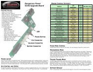
SLG BOARD<br />
Settings and Functions<br />
SLG BOARD<br />
Settings and Functions<br />
BUTTONS AND LED LIGHT INDICATOR<br />
There are two buttons and an LED light indicator mounted inside<br />
the frame of the SLG. These are accessible on the back side of<br />
the frame. The top button is used to turn the SLG ON and OFF.<br />
The bottom button is used to turn the eye feature of the SLG<br />
ON and OFF. To turn the SLG ON press and hold the top button<br />
until the LED light turns on. The eye feature is always on when the<br />
SLG is turned on, to turn off the eye feature press and hold the<br />
bottom button until the LED light starts blinking Red indicating<br />
the eye feature is turned off.<br />
In normal operation mode the LED light indicator shows you the<br />
following information:<br />
Yellow: Boot up Sequence<br />
Red: No ball detected inside the SLG, eye is turned on<br />
Green: Ball detected inside the SLG, eye is turned on<br />
Blinking red: Eye is turned off<br />
Blinking green: Eye blocked. Either the eye is dirty, the<br />
marker is not gassed up, there is bad connection between<br />
the board and the eyes or the battery is low.<br />
SETTINGS AND CONFIGURATION MODE<br />
There are three settings that can be altered on the SLG<br />
circuit board.<br />
1. Trigger sensitivity<br />
2. ROF (Rate Of Fire)<br />
3. Fire Mode<br />
DIP switch 1 is used for factory reset/tournament lock. When it’s<br />
OFF the gun is always set back to stock settings (semiauto, 15<br />
bps, trigger sensitivity 5).<br />
To change the board settings you must turn ON the factory<br />
settings lock. To do this, turn DIP switch number 1 ON.<br />
Settings 1-3 are changed from a configuration mode.<br />
To change settings 1-3 you will need to activate the configuration<br />
mode. To activate the configuration mode, turn your marker off,<br />
open the three left side grip panel screws with a 3 ⁄32” Allen key<br />
and set DIP switch 2 to the ON position. Next, turn your marker<br />
on.<br />
The LED will cycle through all colors for one second to indicate<br />
that you have entered the configuration mode.<br />
To cycle through different settings, pull and release the trigger.<br />
GREEN – TRIGGER SENSITIVITY. Values 1 - 20<br />
(factory default 5)<br />
Trigger sensitivity is the amount of time that the trigger has to be<br />
released before the next trigger pull is allowed. In some situations<br />
with too low of a value, the marker may begin to shoot full-auto.<br />
NOTE: The eye is always activated when you turn the marker on.<br />
6 7<br />
w w w . p r o t o p a i n t b a l l . c o m<br />
w w w . p r o t o p a i n t b a l l . c o m
SLG BOARD<br />
Settings and Functions<br />
SLG BOARD<br />
Settings and Functions<br />
RED – RATE OF FIRE (Values 1-45)<br />
YELLOW – FIRE MODE (Values 1-4)<br />
The ROF setting is used to set the<br />
maximum rate of fire of the SLG.<br />
The values do not correspond directly<br />
to a certain Balls Per Second (BPS)<br />
value. You will need to use the<br />
table below to locate your desired<br />
maximum ROF setting. The factory<br />
default is 20 (12.50 BPS). This setting<br />
is used both when the Eye function is<br />
turned on and off.<br />
The fire mode setting is used to select the fire mode of the SLG. Factory default is semi<br />
automatic mode; one trigger pull shoots out one paintball. The Millennium mode and the PSP<br />
mode follow the rules of the paintball tournament series.<br />
Value 1 – Semi automatic mode<br />
Value 2 – Millennium Mode (2008 rules)<br />
Value 3 – PSP Mode<br />
Value 4 – Full Auto<br />
TO CHANGE A VALUE OF A SETTING<br />
1 9.80 BPS<br />
2 9.90 BPS<br />
3 10.0 BPS<br />
4 10.10 BPS<br />
5 10.20 BPS<br />
6 10.30 BPS<br />
7 10.41 BPS<br />
8 10.52 BPS<br />
9 10.63 BPS<br />
10 10.75 BPS<br />
11 10.86 BPS<br />
12 10.98 BPS<br />
13 11.11 BPS<br />
14 11.62 BPS<br />
15 11.76 BPS<br />
16 11.90 BPS<br />
17 12.04 BPS<br />
18 12.19 BPS<br />
19 12.34 BPS<br />
20 12.50 BPS<br />
21 12.65 BPS<br />
22 12.82 BPS<br />
23 12.98 BPS<br />
24 13.15 BPS<br />
25 13.33 BPS<br />
26 13.51 BPS<br />
27 13.69 BPS<br />
28 13.88 BPS<br />
29 14.08 BPS<br />
30 14.28 BPS<br />
31 14.49 BPS<br />
32 14.70 BPS<br />
33 14.92 BPS<br />
34 15.15 BPS<br />
35 15.38 BPS<br />
36 15.62 BPS<br />
37 15.87 BPS<br />
38 16.12 BPS<br />
39 16.39 BPS<br />
40 16.66 BPS<br />
41 20.0 BPS<br />
42 22.22 BPS<br />
43 25.0 BPS<br />
44 28.57 BPS<br />
45 33.33 BPS<br />
1. While in the configuration mode choose the color you wish to change by pulling the trigger.<br />
2. When the LED indicates the color you wish to change, pull and hold the trigger until the LED<br />
starts to flash.<br />
3. The LED will flash as many times as the previous setting was and it will then turn off. Now pull<br />
the trigger as many times as you wish the new setting to be.<br />
4. When done the LED will cycle through all the colors again to indicate setting was saved and<br />
turn back to green. You can now change another setting or quit the configuration mode.<br />
Normal Mode<br />
Configuration Mode<br />
8 9<br />
w w w . p r o t o p a i n t b a l l . c o m<br />
Increasing ROF too high will increase probability of ball breakage.<br />
If this occurs decrease ROF setting.<br />
w w w . p r o t o p a i n t b a l l . c o m
SLG BOARD<br />
Settings and Functions<br />
TRIGGER<br />
ADJUSTMENT<br />
BATTERY<br />
The 9V battery will last for about 20,000 shots. Please be aware<br />
that there are substantial differences in performance between<br />
different brands of batteries. Use of high quality alkaline or<br />
lithium ion batteries is recommended for maximum battery<br />
life. If you plan not to use your marker for a long period<br />
of time (a month), it is recommended that you remove the<br />
battery from the marker. When the battery voltage starts<br />
to go too low, the marker will not fire with every trigger<br />
pull. For tournament use, it is recommended to change<br />
the battery for each tournament. When changing your<br />
battery, take special care to ensure the wiring harness<br />
is not pinched under the battery.<br />
CHANGING THE BATTERY<br />
The battery is housed on the left side of<br />
the grip frame. To access the battery, remove<br />
the three screws holding the left side grip panel<br />
down. Use a 3 ⁄32” Allen key. Carefully lift the<br />
battery out of the frame, taking care not to damage<br />
the battery lead wires. Clip a new battery into the 9V<br />
connector and carefully place it back into the frame making<br />
sure that no wires are pinched underneath the battery.<br />
• A low battery will not be able to<br />
power both the ACE eye and the<br />
trigger switch, causing ACE eye failure.<br />
• If the battery is low, the marker will<br />
not fire with every trigger pull.<br />
The Trigger’s forward travel and over travel are fully<br />
adjustable so that the user can fine-tune the trigger to his/her<br />
exact preference.<br />
To adjust the trigger an .050 Allen key is needed. There are<br />
two adjustment screws located on the trigger.<br />
The screw on the top front of the trigger controls the forward<br />
travel. Screwing it in will shorten the trigger’s length of<br />
pull. Note: If this screw is screwed too far in, the switch will<br />
be depressed all the time causing the SLG to fire once<br />
immediately after turning it on and not firing after that! (Fig. 1)<br />
The screw on the back of the trigger controls the over travel.<br />
By turning this screw you can adjust how far back the trigger<br />
will travel. Note: If this screw is adjusted too far, the trigger<br />
will not be allowed to travel far enough to depress the switch<br />
and the marker will not fire. (Fig. 2)<br />
The trigger spring used to return the trigger is located inside<br />
the frame. It is not suggested to remove this spring as it<br />
will cause excess wear on the microswitch and cause trigger<br />
bounce.<br />
• Be sure the trigger is not adjusted to the point where it is too sensitive<br />
and may cause accidental discharge of the marker.<br />
• Removing the trigger spring will cause premature wear on the<br />
microswitch resulting in failure.<br />
• Be sure you do not pinch the wires between the frame and body when<br />
reattaching the frame to the body.<br />
10<br />
w w w . p r o t o p a i n t b a l l . c o m<br />
11<br />
w w w . p r o t o p a i n t b a l l . c o m<br />
Fig. 1<br />
Fig. 2
SLG <strong>BOLT</strong><br />
Assembly<br />
Bolt TIP<br />
12<br />
RING<br />
Bolt BACK<br />
<strong>BOLT</strong><br />
(Do not disassemble for<br />
regular maintenance)<br />
soft<br />
rubber<br />
cushion<br />
SILENCER<br />
The SLG <strong>BOLT</strong> is the main component of the SLG marker. In order to<br />
achieve the best possible performance, it is essential that the SLG <strong>BOLT</strong><br />
is kept clean, well lubed and in good working order.<br />
The SLG <strong>BOLT</strong> should be cleaned and re-lubed every 10,000 shots or<br />
after breaking paint or playing in severe conditions.<br />
The SLG bolt kit is composed of a 2 piece bolt, plunger,<br />
and back cap. To remove the bolt kit, unscrew the<br />
back cap using a 1 ⁄4” Allen key. Insert the Allen key into<br />
the back cap, while depressing the bleed button.<br />
If there is any air remaining in the SLG, it will be<br />
purged when the bleed button is depressed. If air<br />
continues to leak from the bleed system, your air system is<br />
still feeding air into the SLG.<br />
De-activate the air system and continue with the bolt<br />
maintenance. Once you have unscrewed the back cap<br />
and removed it from the body, the bolt should slide out.<br />
For regular maintenance there is no reason to<br />
disassemble the bolt kit any further.<br />
PLUNGER<br />
BLEED BUTTON<br />
Back cap<br />
Forward Position<br />
back Position<br />
HOW IT WORKS<br />
SLG <strong>BOLT</strong><br />
OPERATION<br />
At rest, when the bolt is in the rear<br />
position, there is a positive forward<br />
force on the bolt from the air pressure<br />
in the shot chamber. The bolt is held<br />
in the rear position by the sear. When<br />
the SLG is fired, the sear is dropped<br />
by an electro-magnetic solenoid.<br />
The positive forward force drives<br />
the bolt forward until the bolt drops<br />
off the plunger and allows the shot<br />
chamber air to vent down the bolt<br />
and fire the paintball. Once the shot<br />
chamber has been fully vented, the air<br />
supplied to the bolt creates a positive<br />
rearward force that drives the bolt<br />
back and allows it to catch on the sear<br />
again. As the bolt travels rearward,<br />
the shot chamber is filled and the<br />
cycle is repeated.<br />
When servicing your marker:<br />
• Make sure your hopper is removed from the marker.<br />
• Make sure there are no paintballs in the breech of the marker.<br />
• Always remove the air supply and relieve all gas pressure in the marker<br />
before disassembly.<br />
• When using the marker in temperatures below 50° Fahrenheit it may be<br />
necessary to lube the SLG bolt more frequently.<br />
13<br />
w w w . p r o t o p a i n t b a l l . c o m w w w . p r o t o p a i n t b a l l . c o m
SLG <strong>BOLT</strong><br />
OPERATION AND Maintenance<br />
RE-COCKING / BLEED<br />
The SLG is equipped with a<br />
Pneumatic re-cocking system in<br />
case the bolt becomes jammed<br />
(pinching a ball). The button<br />
in the center of the bolt back<br />
can be pressed to send the bolt<br />
rearward and reset it for the next shot.<br />
The bleed button also serves as a gas vent for the dump chamber. It can be used to de-gas the<br />
SLG after the tank is removed, or to confirm that the SLG has gas and is ready for play.<br />
The bleed button is also a safety mechanism. You must depress the button with your Allen key<br />
when removing the bolt kit. If there is air retained in the gun it will be purged before you remove<br />
the bolt kit. The bolt kit should never be removed if there is an air supply feeding the SLG.<br />
MAINTENANCE<br />
The basic maintenance for the SLG <strong>BOLT</strong> is to clean all surfaces of dirt, broken paint or other<br />
debris. Also check for any wear and tear on the O-rings and change them if needed.<br />
1<br />
1<br />
SLG <strong>BOLT</strong><br />
O-RING TABLE<br />
2 2<br />
3<br />
Remove the bolt kit with a 1 ⁄4” Allen key. Apply a thin layer of lube to all o-rings on the bolt and<br />
plunger. Next, slide the bolt into the body. Make sure it moves smoothly. Screw the back cap into<br />
the body.<br />
If the SLG <strong>BOLT</strong> is not kept clean and well lubed you will either start hearing leaks, or over long<br />
period of time physical damage to the SLG <strong>BOLT</strong> components.<br />
To troubleshoot leaks and other bolt problems consult the troubleshooting section at the<br />
end of this manual.<br />
14 15<br />
w w w . p r o t o p a i n t b a l l . c o m<br />
SLG <strong>BOLT</strong> O-RING LIST<br />
1 014 BN 90<br />
2 016 BN 70<br />
3 020 BN 70<br />
4 005 BN 70<br />
w w w . p r o t o p a i n t b a l l . c o m<br />
4
Loaders and feed neck<br />
AIR/NITROGEN<br />
OPTIONS AND INSTALLATION<br />
LOADERS AND FEED NECK<br />
To achieve the maximum<br />
performance of the SLG<br />
you will need to use a<br />
motorized loader that force<br />
feeds paintballs into the<br />
SLG marker, preferably<br />
the Rotor Loader. Using a<br />
slower motorized loader or<br />
a non-motorized loader will<br />
work, but the rate of fire will<br />
be reduced.<br />
To fit a loader onto the<br />
SLG, tighten your loader<br />
into the adjustable feedneck<br />
using a 5/32” Allen key.<br />
Loader should now be held<br />
in with a snug fit.<br />
There is no maintenance<br />
needed for the feed neck<br />
besides keeping it clean<br />
of broken paint, dirt and<br />
debris.<br />
16<br />
AIR / NITROGEN TANK OPTIONS<br />
AND INSTALLATION<br />
The SLG will work with<br />
compressed air, nitrogen, and<br />
CO 2 . Using Compressed air or<br />
Nitrogen will let the SLG achieve<br />
optimal performance, as it will<br />
improve the consistency of the SLG.<br />
If CO 2 is used, take note that outside<br />
temperature will affect the expansion<br />
rate of the CO 2 and consequently the<br />
velocity of the paintballs. Using CO 2 in<br />
cold weather will lead to inconsistent<br />
velocities and reduced efficiency. If you<br />
intend to use the SLG in cold weather,<br />
using a compressed air or nitrogen<br />
system such as the DYE Throttle air system<br />
is recommended.<br />
The output pressure from the air system must<br />
be between 400 – 850psi.<br />
To install an air system, screw the tank into the<br />
airport all the way as far as it goes. To remove the<br />
air system, unscrew from the airport. There will be<br />
gas leaking for a few seconds while you screw the<br />
air system out. Notice that even with the air system<br />
removed there can be gas inside the SLG and it can still<br />
fire a paintball. Always treat the marker as being live and<br />
never point it to anything you don’t intend to shoot.<br />
17<br />
w w w . p r o t o p a i n t b a l l . c o m w w w . p r o t o p a i n t b a l l . c o m
airport<br />
Assembly and Maintenance<br />
airport<br />
Assembly and Maintenance<br />
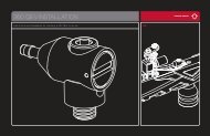
AIRPORT ADJUSTMENT AND<br />
MAINTENANCE<br />
The location of the airport<br />
adapter can be moved<br />
approximately 1 1 ⁄4” back or<br />
forward from the stock position<br />
to fit your individual preference.<br />
To change the position:<br />
1. Open the three left side grip<br />
panel screws with a 3 ⁄32”<br />
Allen key.<br />
2. Remove the 9V battery.<br />
3. Using a 3 ⁄32” Allen key, loosen<br />
the airport locking screw until<br />
airport slides back and forth<br />
loosely.<br />
4. Set the airport to the desired<br />
position.<br />
5. Tighten airport locking screw,<br />
install the 9V battery and tighten the three grip panel screws.<br />
When screwing the air system into the airport, always check that the<br />
threads on the air system and the airport are clean and not worn out. If<br />
you think the threads are not in good condition, contact DYE Precision<br />
or a professional store before screwing in the air system.<br />
AIRPORT PIN DEPRESSOR<br />
The airport on the SLG comes with an adjustable pin depressor. It’s preset to work with most of<br />
the systems on the market, but if needed it can be adjusted.<br />
To adjust the pin depressor remove the hose from the front of the airport by pushing the gray<br />
plastic housing towards the fitting and pulling the hose out. Next, use a 5 ⁄64” Allen key to move the<br />
set screw mounted inside the airport. Turn the screw back a few turns so that the pin valve on the<br />
air system will never be pressed.<br />
Next:<br />
1. Screw the air system into the airport all the way, no air should come out.<br />
2. Turn the pin depressor screw in until a small amount of air starts to come out.<br />
3. Turn the air system out about half a turn, air leak should stop.<br />
4. Screw in the pin depressor screw enough for air to start leaking again.<br />
5. Screw out the air system and connect hose again.<br />
6. Now the pin depressor screw is set to the optimal point for<br />
your air system.<br />
If the screw is set too far out the pin valve on the air system is<br />
opened too early and air will leak out through the exhaust hole<br />
on the top of the airport. If the screw is not in far enough,<br />
the pin valve on the airport will never be opened or<br />
will be opened too little for good flow.<br />
18 19<br />
w w w . p r o t o p a i n t b a l l . c o m<br />
w w w . p r o t o p a i n t b a l l . c o m
hyper3 IN-LINE REGULATOR<br />
Adjustments and Maintenance<br />
hyper3 IN-LINE REGULATOR<br />
Adjustments and Maintenance<br />
VELOCITY ADJUSTMENT<br />
The velocity of the SLG is adjusted by adjusting the input<br />
pressure into the SLG. This is controlled with the Hyper3<br />
regulator. The Hyper3 on the SLG is factory set to 145 psi which<br />
will give you a velocity of about 285 FPS (Feet per Second).<br />
A 3 ⁄16” Allen key will be needed for this operation. Turning the<br />
adjustment screw in (clockwise) will decrease the pressure, and<br />
out (counterclockwise) will increase the pressure. To adjust the<br />
velocity:<br />
1. Make sure you and everybody around you is wearing ASTM/<br />
CE approved paintball goggles.<br />
2. Shoot the SLG over a paintball chronograph.<br />
3. To lower the velocity turn the Hyper3 adjustment screw in.<br />
To increase the velocity turn the screw out. Only turn the screw<br />
a quarter turn at a time and shoot over the chronograph again.<br />
Notice that a few shots are needed before the change can be<br />
seen on the chronograph.<br />
Hyper3 REGULATOR DIS-ASSEMBLY INSTRUCTIONS<br />
To disassemble the Hyper3 regulator you will need a C-clip tool or a strong pick. Remove the<br />
C-clip from the bottom of the Hyper 3 reg. Next, unscrew the Brass seat housing from the body<br />
with a 3⁄16” Allen key.<br />
To change the seat, pull out the old seat from the housing with a sharp object. Insert the new seat<br />
in place and push it down with a flat object. Notice that it takes about 2000 shots for the seat to<br />
perfectly sit into the seat housing. This is called the break in period for the regulator.<br />
Remember to apply lube to the 010 on the brass reg seat housing before re-assembly.<br />
Further disassembly to service the top section of the Hyper3 should be performed by<br />
a trained Tech.<br />
SEAT HOUSING Regulator seat BODY Top Cap<br />
MAINTENANCE<br />
For the SLG to function properly, it is essential that the input<br />
pressure into the marker stays consistent at all times. The general<br />
maintenance needed for the Hyper3 regulator is to keep it clean<br />
of dirt and debris at all times. A more extensive service should<br />
be performed every 12 months by a trained Tech or if the output<br />
pressure of the regulator doesn’t stay consistent. This can be seen<br />
as inconsistent velocity and verified with a regulator tester (sold<br />
separately). Notice that the Hyper3 has a break in period of about<br />
2000 shots before it achieves the best performance.<br />
20 21<br />
w w w . p r o t o p a i n t b a l l . c o m<br />
C-CLIP<br />
w w w . p r o t o p a i n t b a l l . c o m<br />
011 BN 70
ANTI CHOP EYEs/ BALL DETENTS<br />
MAINTENANCE AND CHANGING<br />
ANTI CHOP EYEs/ BALL DETENTS<br />
MAINTENANCE AND CHANGING<br />
Anti chop eyes<br />
The Anti Chop Eye (ACE)<br />
system will prevent the SLG<br />
from chopping paint by not<br />
allowing the marker to fire until<br />
a ball is fully seated in front of<br />
the bolt. The eyes use a beam<br />
across the breech. On one side<br />
there is a transmitter, and on<br />
the opposite side a receiver. In<br />
order for the marker to fire with<br />
the eyes turned on, the signal<br />
between the two eyes must<br />
be broken. After every shot,<br />
before the next ball drops in<br />
the breech, the eye transmitter<br />
and receiver must see each<br />
other. If the eyes are dirty and<br />
cannot see each other between<br />
shots, the LED on the board<br />
will start blinking green. This means that the eyes are dirty. This is an extremely reliable system<br />
as long as the eyes are kept clean. The most common reason for dirty eyes is broken paint. If the<br />
eyes become dirty the marker will default to a reduced rate of fire to prevent chopping. If this<br />
happens during game play, you can bypass this by turning the eyes off. Clean the eyes as soon as<br />
possible.<br />
NOTE: If the battery is low, the marker may act as if the eyes are dirty or not<br />
fire at all. In this case, replace the battery.<br />
Cleaning the Anti chop eyes<br />
Quite often, just cleaning the breech out with a swab will clean the eyes well enough for them<br />
to read one another. For a thorough cleaning, the best method is to use air. Using an air hose or<br />
canned air (typically used for dusting keyboards) works best.<br />
Blow the eyes clean from inside the breech. If you feel the eyes still need a more detailed<br />
cleaning, remove the eye cover to gain full access to the eyes.<br />
To remove the eye cover, you will need a 1 ⁄16” Allen key.<br />
NOTE: Regular eye cleaning is recommended even if no paint is broken. Clean the eyes every two<br />
months or 10,000 shots to eliminate any built up dirt. Excess grease from the front bolt O-ring<br />
can build up in front of the eyes. Remember to check for this after greasing the bolt and cycling<br />
the marker a few times.<br />
Do not remove grip frame without removing eye-plates first.<br />
Changing Ball Detents<br />
The ball detent system is also located under the eye covers. The ball detent system needs little<br />
or no maintenance. There is a spring behind each detent, which holds the detent forward. This<br />
spring pressure should be easily overcome with very little force, such as a paintball moving past.<br />
If you are experiencing double feeding or chopping, check the condition of your ball detents<br />
with your finger to make sure they are not stuck in the up or down position and that they move<br />
in and out of the breech freely. If excessive broken paint or dirt has jammed your ball detents,<br />
remove the eye plates (being careful not to lose the detent springs) and pull the detents out<br />
for a thorough cleaning. Reinstall the detents, springs and eye covers after you have sufficiently<br />
cleaned the detents and breech.<br />
NOTE: Take care when replacing the eye cover to not pinch eye wires.<br />
Over-tightening the retaining screw could result in stripping the threads.<br />
22 23<br />
w w w . p r o t o p a i n t b a l l . c o m<br />
w w w . p r o t o p a i n t b a l l . c o m
Trouble Shooting Guide<br />
AIR LEAKS<br />
Air leaking from the airport<br />
• Check the O-ring on the Air system. If needed<br />
change the O-ring and try again. The O-ring<br />
normally used is #15 but some manufacturers<br />
might use a different size. Consult the manual<br />
of the air system you are using.<br />
• Check that the hose connector is tight.<br />
Remove the hose from the connector by<br />
pushing the gray plastic towards the connector<br />
and pull out hose. Insert a 3 ⁄16” Allen key into<br />
the connector and tighten. If needed, remove<br />
and apply thread sealant to the thread and<br />
re-tighten. If unsure consult expert advice.<br />
• Check that the end of the hose is cut straight<br />
and is not worn out. If needed cut a small piece<br />
off the hose with a razor blade and re-insert<br />
hose into the fitting. Make sure hose goes all<br />
the way to the end.<br />
• Consult page 19 for pin depressor adjustment.<br />
Air leaking from the Hyper3 regulator<br />
• First locate the position of the leak.<br />
• For dis-assembly instructions consult the<br />
technical section under Hyper3 regulator.<br />
• If the leak is coming from the bottom of the<br />
regulator you will need to dis-assemble the<br />
regulator and change the #010 O-ring and the<br />
seat on the brass seat retainer mounted inside<br />
the Hyper3 regulator.<br />
<br />
• If the leak is from the top of the regulator<br />
change the #012 O-ring on the outside of<br />
the cap.<br />
• Otherwise consult a trained Tech to repair<br />
the Hyper3.<br />
Air leaking from the ASA<br />
• Change the #011 O-ring on the top cap of<br />
the Hyper3 and apply a small amount of lube<br />
to the O-ring.<br />
Air leaking between body and frame<br />
• One of the gas passages could be leaking.<br />
Gas up the SLG without the frame attached<br />
and try to locate the exact point of leakage.<br />
If leak is coming from one of the blocked holes<br />
remove the screw, apply some thread sealant<br />
and re-attach screw to the body.<br />
Air leaking from back of the slg<br />
• Check that the bolt kit is tightened all the way<br />
into the SLG. If the bolt kit is loose, it will<br />
start to leak.<br />
• If above does not solve the leak, remove the<br />
bolt kit and change the #020 O-ring on the<br />
back part of the bolt.<br />
• Replace the #O12 O-ring on the plunger.<br />
• If leak persists, replace the two #005 O-rings<br />
on the bleed button.<br />
Air leaking from front of the slg<br />
• Remove the Bolt kit from the marker and<br />
change the front #016 O-ring on the bolt<br />
w w w . p r o t o p a i n t b a l l . c o m<br />
and the #014 O-ring located on the plunger.<br />
Clean the gun bore, lube well and re-assemble.<br />
• If above doesn’t help, make sure that the bolt is<br />
screwed together snugly.<br />
PROBLEMS WITH ELECTRONICS<br />
SLG won’t turn on<br />
• Make sure battery is new and well charged.<br />
• Check that battery is connected to the 9V clip<br />
inside the SLG and that the other end of the<br />
9V harness is connected to the board.<br />
• Make sure there is no dirt or debris blocking<br />
the button from being pressed.<br />
SLG will turn on / off by itself or the<br />
eyes will turn on / off by themselves<br />
• Both of these problems are caused because<br />
the button(s) are pressed all the time.<br />
• Remove board from the frame by removing<br />
the grip panel on the left hand side,<br />
disconnecting the cables and pulling the board<br />
out. Carefully remove the two buttons and<br />
clean them well.<br />
• Re-assemble and test. If problems persist,<br />
contact authorized service center for board<br />
replacement.<br />
Eyes will not work, LED keeps<br />
blinking green<br />
• First change the battery. The eyes are normally<br />
the first thing to stop working when a battery<br />
is dying.<br />
Trouble Shooting Guide<br />
w w w . p r o t o p a i n t b a l l . c o m<br />
• Next try to clean the eyes. You can either use<br />
canned air and blow out the eye holes through<br />
the feed neck hole or remove the eye plates<br />
with a 1 ⁄16” Allen key, pull out the eyes from the<br />
mounting holes carefully and clean them with<br />
q-tips. To test if the eyes work make sure there<br />
is nothing inside the breech and that the bolt is<br />
in the back position. Turn on the SLG, the<br />
light should be red after the boot up sequence.<br />
If it is, the eyes are working.<br />
• Check that the eye wire is connected to the<br />
board so that metal clips are facing down.<br />
• If nothing above helps contact a store or DYE<br />
Precision for eye replacement.<br />
Solenoid will not activate /<br />
Trigger not working<br />
• Check that the trigger adjustment is not set<br />
so that the microswitch cannot activate.<br />
You should hear a small click when pulling<br />
the trigger.<br />
• If the SLG fires once when turned on but<br />
not after that your trigger is set so that the<br />
micro switch is always activated. Re-adjust<br />
the trigger.<br />
• If the trigger is correctly adjusted but the SLG<br />
still won’t fire check that the microswitch<br />
cable is well inserted into the board and to the<br />
correct connector (the microswitch connector<br />
is white and plugs into the white female<br />
connector on the board).<br />
24 25
Trouble Shooting Guide<br />
• Change the battery if not positive about it’s<br />
charge.<br />
• Check that the solenoid cable is attached to<br />
the blue female connector on the board.<br />
Trigger bounce / slg shooting<br />
more than one ball per pull in semi<br />
automatic mode<br />
• Raise the trigger sensitivity level in the <br />
configuration mode.<br />
• Check that the trigger is not adjusted too short.<br />
• Make sure there is a trigger spring inside the<br />
frame.<br />
• Be sure the bolt is screwed together snugly.<br />
ERRATIC VELOCITY / SLG WON’T FIRE<br />
Slg fires but balls are dropping off<br />
or not even coming out of the barrel<br />
• Make sure the battery is good.<br />
• Make sure bolt is clean, well lubed, and moves<br />
well. If there is too much friction in the bolt it<br />
will cause the SLG to shoot down.<br />
• Make sure air system is screwed in all the way.<br />
• Make sure airport screw is adjusted correctly.<br />
• Make sure the front bumper O-ring is not<br />
blocking the inlet hole located on the back<br />
of the bolt.<br />
SLG will not fire but solenoid clicks<br />
• Press the bleed button on the back of the bolt<br />
several times, listen for bolt moving rear wards.<br />
If the bolt is still not moving, depressure the<br />
SLG and remove back and bolt, add lube to<br />
the bolt and reassemble.<br />
First shot is too high<br />
• Change the Seat inside the Hyper3 regulator.<br />
For dis-assembly instructions consult the<br />
technical section on page 21.<br />
Velocity is not consistent<br />
• Make sure the paintballs you are using fit the<br />
barrel good and are consistent in size.<br />
The stock barrel with the SLG is .690 size.<br />
You should be able to blow the paintball<br />
through the barrel but they should not roll<br />
through the barrel on their own.<br />
• Remove the bolt kit and re-lube it. Change any<br />
o-rings causing a lot of friction. Make sure<br />
#014 O-ring in bolt tip is in place and in good<br />
condition.<br />
• Change the battery.<br />
• Check that the Hyper3 regulator is working<br />
good and that the pressure is consistent.<br />
A separate regulator testing tool is available<br />
for this. If needed, dis-assemble and change<br />
worn out O-rings in the Hyper3 regulator.<br />
OTHER CATEGORIES<br />
Double feeding<br />
• If you get two balls firing at once check to see<br />
that the Ball Detents are not stuck down.<br />
• Make sure the Ball Detents are not excessively<br />
worn.<br />
Breaking paint<br />
• Make sure you use high quality paintballs and<br />
that they are stored according to the <br />
manufacturers instructions.<br />
• Check that #14 O-ring on bolt tip is in place<br />
and in good condition.<br />
• Make sure your loader is working and that the<br />
rate of fire is not set higher than the maximum<br />
feed rate of the loader.<br />
• Check that the barrel you are using is not too<br />
tight for the paintballs you are using.<br />
• Eyes are clean/on.<br />
Trouble Shooting Guide<br />
26 27<br />
w w w . p r o t o p a i n t b a l l . c o m<br />
NOTES:<br />
w w w . p r o t o p a i n t b a l l . c o m
1<br />
EXPLODED VIEW<br />
SLG WARRANTY INFORMATION<br />
Warranty and legal information<br />
3<br />
12<br />
2<br />
5<br />
2<br />
12<br />
15<br />
14<br />
3<br />
4<br />
10<br />
11<br />
PARTS LIST<br />
1 Feed Neck<br />
2 Ball Detent<br />
3 Eye Cover<br />
4 SLG Body<br />
5 “ACE” Eye<br />
6 Hyper3<br />
7 Front Frame Screw<br />
WARRANTY<br />
DYE Precision, Inc. warrants for one year to the initial retail purchaser, from the initial date of purchase,<br />
that the paintball marker and regulator are free from defects in materials and workmanship, subject to<br />
the requirements, disclaimers and limitations of this warranty. Disposable parts, normal maintenance<br />
and standard wear and tear parts such as batteries, O-rings and seals are not covered under warranty.<br />
The solenoid and electronic components on the marker are covered under warranty for six months.<br />
This warranty does not cover scratches, nicks, improper disassembly, improper re-assembly, misuse,<br />
neglect or improper storage. Modification to the product will void the warranty. The only authorized<br />
lubricant for the marker is Slick Lube. Use of any other lubricant will void your warranty. This<br />
warranty is limited to repair or replacement of defective parts with the customer to pay shipping costs.<br />
Warranty card and proof of purchase must be submitted to DYE Precision for warranty to be in effect.<br />
This warranty is not transferable. This warranty does not cover performance. Paintball markers are<br />
non-refundable.<br />
TECHNICAL SUPPORT<br />
Our Technical Support Departments are open Monday through Friday.<br />
DYE Precision, Inc. can be reached at 858-536-5183 ext.277 from 9am to 5pm PST.<br />
DYE Europe can be reached at +44 (0) 20-8649-6330 from 9am to 5pm GMT.<br />
DYE Asia can be reached at 886 (0) 4-2407-9135 from 9am to 5pm GMT +8 hours.<br />
Additional support and international contacts are available through our web site, www.dyepaintball.com.<br />
DISCLAIMER<br />
The specifications & photographs in this material are for information and general guidance purposes<br />
only. Our products are continually updated and changes may be made to specification, design or<br />
appearance from time to time. These are subject to change without notice. Contents of box may<br />
therefore vary from owner’s manual. For details of changes in design, specification or appearance<br />
consult your local distributor or dealer. The SLG <strong>BOLT</strong> and Slick Lube are registered trademarks.<br />
Design rights, copyrights and all other rights reserved. All patterns, drawings, photographs, instructions<br />
or manuals remain the intellectual property of the manufacturer.<br />
DYE Precision, Inc. U.S. Patent # 5,613,483. OTHER U.S. AND INT’L PATENTS PENDING. Covered by<br />
one or more of the following U.S. Patents, 5,613,483; 5,881,707; 5,967,133; 6,035,843 and 6,474,326.<br />
All rights will be strictly enforced.<br />
6<br />
7<br />
9<br />
8 45 Frame<br />
9 Rear Frame Screw<br />
10 SLG Bolt<br />
11 SLG Back Cap<br />
12 Eye Cover Screw<br />
13 Airport<br />
14 Sear<br />
15 Sear Spring<br />
DYE Precision, Inc.<br />
10637 Scripps Summit Ct.<br />
San Diego, CA. 92131<br />
DYE Europe<br />
Dye House,<br />
7-8 Commerce Way<br />
Croydon, Surrey<br />
United Kingdom CR0 4XA<br />
13<br />
28 29<br />
w w w . p r o t o p a i n t b a l l . c o m<br />
DYE Asia<br />
No. 253, Guojhong Rd.<br />
Dali City, Taichung County 412<br />
Taiwan (R.O.C.)