Tech. Explanations - Kendrion Binder
Tech. Explanations - Kendrion Binder
Tech. Explanations - Kendrion Binder

You also want an ePaper? Increase the reach of your titles
YUMPU automatically turns print PDFs into web optimized ePapers that Google loves.
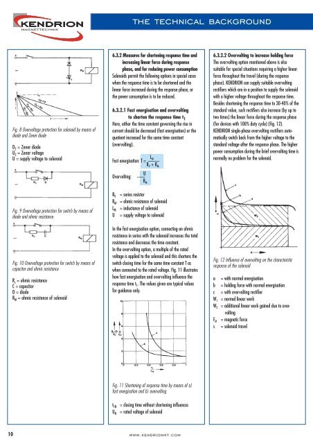
the technical background<br />
Fig. 8 Overvoltage protection for solenoid by means of<br />
diode and Zener diode<br />
D Z = Zener diode<br />
U Z = Zener voltage<br />
U = supply voltage to solenoid<br />
6.3.2 Measures for shortening response time and<br />
increasing linear force during response<br />
phase, and for reducing power consumption<br />
Solenoids permit the following options in special cases<br />
when the response time is to be shortened and the<br />
linear force increased during the response phase, or<br />
the power consumption is to be reduced.<br />
6.3.2.1 Fast energisation and overvolting<br />
to shorten the response time t 1<br />
Here, either the time constant governing the rise in<br />
current should be decreased (fast energisation) or the<br />
quotient increased for the same time constant<br />
(overvolting).<br />
L M<br />
Fast energisation: T = ———<br />
R V + R M<br />
Overvolting:<br />
U<br />
——<br />
RM<br />
6.3.2.2 Overvolting to increase holding force<br />
The overvolting option mentioned above is also<br />
suitable for special situations requiring a higher linear<br />
force throughout the travel (during the response<br />
phase). KENDRION can supply suitable overvolting<br />
rectifiers which are in a position to supply the solenoid<br />
with a higher voltage throughout the response time.<br />
Besides shortening the response time to 30-40% of the<br />
standard value, such rectifiers also increase (by up to<br />
two times) the linear force during the response phase<br />
(for devices with 100% duty cycle) (Fig. 12).<br />
KENDRION single-phase overvolting rectifiers automatically<br />
switch back from the higher voltage to the<br />
standard voltage after the response phase. The higher<br />
power consumption during the brief overvolting time is<br />
normally no problem for the solenoid.<br />
Fig. 9 Overvoltage protection for switch by means of<br />
diode and ohmic resistance<br />
R V<br />
R M<br />
L M<br />
U<br />
= series resistor<br />
= ohmic resistance of solenoid<br />
= inductance of solenoid<br />
= supply voltage to solenoid<br />
M<br />
Fig. 10 Overvoltage protection for switch by means of<br />
capacitor and ohmic resistance<br />
R s = ohmic resistance<br />
C = capacitor<br />
D = diode<br />
R M = ohmic resistance of solenoid<br />
In the fast energisation option, connecting an ohmic<br />
resistance in series with the solenoid increases the total<br />
resistance and decreases the time constant.<br />
In the overvolting option, a multiple of the rated<br />
voltage is applied to the solenoid and this shortens the<br />
switch closing time for the same time constant T as<br />
when connected to the rated voltage. Fig. 11 illustrates<br />
how fast energisation and overvolting influence the<br />
response time t 1 . The values given are typical values<br />
for guidance only.<br />
Fig. 12 Influence of overvolting on the characteristic<br />
response of the solenoid<br />
a<br />
b<br />
c<br />
W 1<br />
W 2<br />
F M<br />
s<br />
= with normal energisation<br />
= holding force with normal energisation<br />
= with overvolting rectifier<br />
= normal linear work<br />
= additional linear work gained due to overvolting<br />
= magnetic force<br />
= solenoid travel<br />
Fig. 11 Shortening of response time by means of a)<br />
fast energisation and b) overvolting<br />
t 1N<br />
U N<br />
= closing time without shortening influences<br />
= rated voltage of solenoid<br />
10<br />
www.kendrionmt.com