Tech. Explanations - Kendrion Binder
Tech. Explanations - Kendrion Binder
Tech. Explanations - Kendrion Binder

Create successful ePaper yourself
Turn your PDF publications into a flip-book with our unique Google optimized e-Paper software.
the technical background<br />
6.3.2.3 Economy mode to reduce power<br />
consumption<br />
It is not always necessary to increase the linear force<br />
during the response phase (see 6.3.2.2). There are<br />
applications in which the holding force achieved at the<br />
end of the response phase permits a decrease in the<br />
power consumption and hence also the temperature of<br />
the solenoid. Fig. 13 shows a circuit for such an<br />
economy mode. Here, once the plunger has reached its<br />
end position, a switch is actuated to connect a resistor<br />
with the solenoid in series. This resistor is shortcircuited<br />
by the switch during the response phase.<br />
This results in the following designations:<br />
plunger in initial position and during response time<br />
P 1 = U · I 1 = I 2 1 · R M<br />
Plunger in end position with power reduction<br />
P 2 = U · I 2 = I 2 2 · (R M + R V )<br />
U<br />
R M<br />
I 2 = ——— = I 1 · ———<br />
R M + R V R M + R V<br />
P 1 = input power s 1<br />
R M = resistance of energisation coil<br />
R V = series resistor<br />
R V can be designed with a value of up to two times the<br />
resistance of the solenoid. (The exact value must be<br />
determined by experimentation.) Fig. 14 shows the<br />
magnetic forces for various input powers.<br />
6.4 Input power and ambient temperature<br />
The input power values specified on the product data<br />
sheets were determined for an ambient temperature of<br />
20°C. However, the energisation coils designed for this<br />
temperature can be operated in ambient temperatures<br />
up to 40°C. In doing so, the maximum permissible<br />
long-term temperature for the insulation used as given<br />
in DIN VDE 0580 point 3.3 Tab. 1 is reached, but not<br />
exceeded. The specified values for magnetic force and<br />
linear work are reached at the operating temperature<br />
and 90% of the rated voltage. The operating<br />
temperature is the temperature during operation with<br />
the specified data, increased by the reference ambient<br />
temperature of +40°C.<br />
The input power must be reduced for ambient<br />
temperatures higher than 40°C. This also reduces the<br />
linear work. In certain circumstances this also applies<br />
when the solenoid is fitted to part of a machine that<br />
reaches operating temperatures higher than 40°C. The<br />
reduction in the input power can be achieved by way<br />
of a special energisation coil or by operating the<br />
solenoid with a lower voltage.<br />
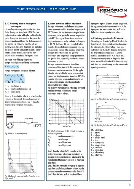
Fig. 15 shows the rated voltage, rated input power and<br />
rated linear work in relation to the ambient<br />
temperature for a DC solenoid.<br />
input power adjusted to suit the ambient temperature.<br />
For a guaranteed ambient temperature < 40°C, the<br />
input power and hence also the linear work can be<br />
higher than the corresponding rated value.<br />
6.5 Switching operations for DC solenoids<br />
The oscillograms shown in Figs 16 and 17 indicate the<br />
typical current, voltage and solenoid travel conditions<br />
for a DC solenoid in relation to time t when being<br />
switched on and off. The two diagrams clearly show<br />
the different behaviour depending on whether<br />
switching is carried out on the DC or the AC side.<br />
The response times specified on the product data<br />
sheets are reliably achieved at 70% of the rated magnetic<br />
force and at rated voltage with the solenoid at its<br />
operating temperature.<br />
Fig. 16 Switching behaviour with switching on DC side<br />
Fig. 13 Circuit for economy mode<br />
M<br />
Fig. 14 Magnetic forces and holding forces for various<br />
input powers P<br />
Fig. 15 Operating modes for DC solenoids in relation to<br />
ambient temperature<br />
ϑ 13 = ambient temperature<br />
U N = rated voltage<br />
W N = rated linear work<br />
= rated input power<br />
P N<br />
Line 1 shows the voltage (in %) in relation to the<br />
ambient temperature with which a solenoid may be<br />
operated when its energisation coil is designed for the<br />
normal ambient temperature (as given on the product<br />
data sheet).<br />
Line 2 shows the permissible input power as a percentage<br />
of the specified value when the solenoid must be<br />
operated in an ambient temperature other than 40°C.<br />
Line 3 shows the linear work of the solenoid for an<br />
Fig. 17 Switching behaviour with switching on AC side<br />
ED= coil ON time<br />
I = current<br />
U = voltage<br />
s = solenoid travel<br />
t = time<br />
t 1 = response time<br />
t 11 = response delay<br />
t 12 = travel time<br />
t 2 = release time<br />
t 21 = release delay<br />
t 22 = return time<br />
www.kendrionmt.com 11