Tech. Explanations - Kendrion Binder
Tech. Explanations - Kendrion Binder
Tech. Explanations - Kendrion Binder

Create successful ePaper yourself
Turn your PDF publications into a flip-book with our unique Google optimized e-Paper software.
the technical background<br />
Response delay (t 11 ):<br />
is the time between switching on the energisation<br />
current and the plunger beginning to move.<br />
Travel time (t 12 ):<br />
is the time taken by the plunger to move from its<br />
initial position to its end position.<br />
Release delay (t 21 ):<br />
is the time between switching off the energisation current<br />
and the plunger beginning to move back.<br />
Return time (t 22 ):<br />
is the time taken by the plunger to move from its end<br />
position back to its initial position.<br />
7. SI units and symbols used in equations<br />
The SI units and symbols used in equations as given on<br />
the product data sheets and in the technical data are<br />
taken from DIN 1304. The most important variables<br />
used in the design of the devices are listed on page 15.<br />
8. Testing of solenoids<br />
8.1 Test voltage<br />
All KENDRION solenoids are tested to ascertain their<br />
dielectric strength before leaving the factory. The test<br />
voltages used are given in DIN VDE 0580 point 5.3.1.<br />
8.1.2 Renewed voltage test<br />
The voltage test carried out during routine testing<br />
should not be repeated if it can be avoided. However,<br />
if a second test is called for, e.g. as an acceptance<br />
criterion, then this should be carried out with only 80%<br />
of the test voltage given in Tab. 4 below.<br />
9. Electromagnetic time constants ( )<br />
and inductances (L)<br />
The electromagnetic time constants (ms) for the initial<br />
and end positions of the plunger are specified on the<br />
product data sheets in order to determine the inductances<br />
of DC linear solenoids. These time constants allow the<br />
inductances to be calculated for various duty cycles and<br />
rated voltages according to the following example:<br />
Given:<br />
Wanted:<br />
Answer:<br />
solenoid type LHS060...<br />
duty cycle = 100%<br />
rated voltage = 24 VDC<br />
inductance LIP (H) for initial position of<br />
plunger inductance LEP (H) for end posi<br />
tion of plunger<br />
input power P20 = 26 W<br />
(specified on data sheet)<br />
According to Ohm’s law, the resistance of the energisation<br />
coil can be calculated from the input power as follows:<br />
2 2 2<br />
R = ——<br />
U<br />
= ———<br />
24 [V ]<br />
= 22 Ω<br />
26 [W]<br />
P 20<br />
Inductance at initial position:<br />
L IP =<br />
Inductance at end position:<br />
L EP =<br />
- -3<br />
IP · R = 4[ms] · 10 · 22 [Ω] = 88mH<br />
EP · R = 4,3 [ms] · 10 · 22 [Ω] = 95mH<br />
Make sure that the time constants are entered in milliseconds<br />
(ms) for these calculations, i.e. time constant<br />
values specified in seconds (s) must be multiplied by<br />
10 -3 .<br />
-3<br />
10. Operating conditions<br />
Our AC and DC linear solenoids are designed for the<br />
following operating conditions:<br />
10.1 An ambient temperature of 35°C. The minimum<br />
ambient temperature is -5°C.<br />
10.2 The Relative humidity of the air depends<br />
on the ambient temperature and is approx. 50% at<br />
35°C. Higher relative humidities are permissible at<br />
lower temperatures. Consideration should be given to<br />
the formation of condensation water.<br />
10.3 Please adhere to our installation guidelines<br />
when putting the devices into operation.<br />
11. Service life<br />
The service life of devices and associated wear parts<br />
depends on the installation and operating conditions,<br />
e.g. mounting position, load etc.<br />
12. Notes for DC and AC linear solenoids<br />
12.1 Installation<br />
Connect the plunger to the machine part by means of<br />
an interlocking, non-rigid link that allows sufficient<br />
play.<br />
12.2 Mounting position<br />
Our DC linear solenoids can be mounted in any position.<br />
The force transfer is preferably in the axial direction.<br />
12.3 Putting into operation<br />
The supply voltage must match the rated voltage as<br />
given on the rating plate. The user is responsible for<br />
observing the instructions and requirements described<br />
in DIN VDE 0580 (July 2000).<br />
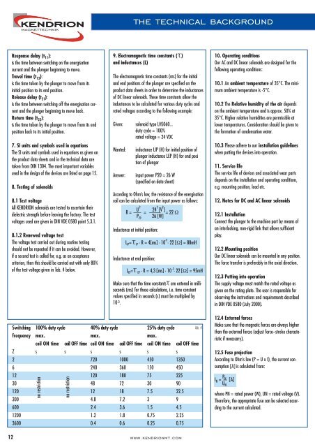
Switching<br />
frequency<br />
Z<br />
2<br />
6<br />
12<br />
30<br />
120<br />
300<br />
600<br />
1200<br />
3600<br />
100% duty cycle<br />
max.<br />
coil ON time coil OFF time<br />
s<br />
s<br />
no restriction<br />
no restriction<br />
40% duty cycle<br />
max.<br />
coil ON time coil OFF time<br />
s<br />
s<br />
720<br />
1080<br />
240<br />
360<br />
120<br />
180<br />
48<br />
72<br />
12<br />
18<br />
4.8<br />
7.2<br />
2.4<br />
3.6<br />
1.2<br />
1.8<br />
0.4<br />
0.6<br />
25% duty cycle<br />
max.<br />
coil ON time coil OFF time<br />
s<br />
s<br />
450<br />
1350<br />
150<br />
450<br />
75<br />
225<br />
30<br />
90<br />
7.5<br />
22.5<br />
3<br />
9<br />
1.5<br />
4.5<br />
0.75 2.25<br />
0.25 0.75<br />
Tab. 4<br />
12.4 External forces<br />
Make sure that the magnetic forces are always higher<br />
than the external forces (adjust force–stroke characteristic<br />
if necessary).<br />
12.5 Fuse projection<br />
According to Ohm’s law (P = U x I), the current consumption<br />
[A] is calculated from:<br />
P N IN = — [A]<br />
U N<br />
where PN = rated power (W), UN = rated voltage (V).<br />
Therefore, the appropriate fuse can be selected according<br />
to the current calculated.<br />
12<br />
www.kendrionmt.com