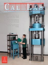
METROLOGY 101: PISTON PROVER DESIGN - Cal Lab Magazine
METROLOGY 101: PISTON PROVER DESIGN - Cal Lab Magazine
METROLOGY 101: PISTON PROVER DESIGN - Cal Lab Magazine

Create successful ePaper yourself
Turn your PDF publications into a flip-book with our unique Google optimized e-Paper software.
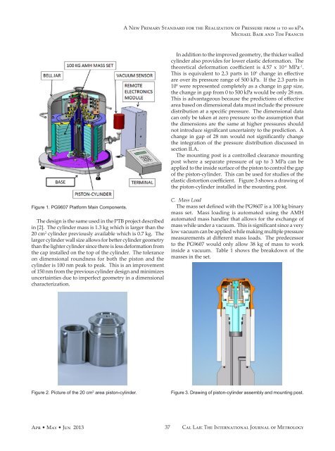
A New Primary Standard for the Realization of Pressure from 10 to 500 kPa<br />
Michael Bair and Tim Francis<br />
BASE<br />
Figure 1. PG9607 Platform Main Components.<br />
The design is the same used in the PTB project described<br />
in [2]. The cylinder mass is 1.3 kg which is larger than the<br />
20 cm 2 cylinder previously available which is 0.7 kg. The<br />
larger cylinder wall size allows for better cylinder geometry<br />
than the lighter cylinder since there is less deformation from<br />
the cap installed on the top of the cylinder. The tolerance<br />
on dimensional roundness for both the piston and the<br />
cylinder is 100 nm peak to peak. This is an improvement<br />
of 150 nm from the previous cylinder design and minimizes<br />
uncertainties due to imperfect geometry in a dimensional<br />
characterization.<br />
In addition to the improved geometry, the thicker walled<br />
cylinder also provides for lower elastic deformation. The<br />
theoretical deformation coefficient is 4.57 x 10 -6 MPa -1 .<br />
This is equivalent to 2.3 parts in 10 6 change in effective<br />
are over its pressure range of 500 kPa. If the 2.3 parts in<br />
10 6 were represented completely as a change in gap size,<br />
the change in gap from 0 to 500 kPa would be only 28 nm.<br />
This is advantageous because the predictions of effective<br />
area based on dimensional data must include the pressure<br />
distribution at a specific pressure. The dimensional data<br />
can only be taken at zero pressure so the assumption that<br />
the dimensions are the same at higher pressures should<br />
not introduce significant uncertainty to the prediction. A<br />
change in gap of 28 nm would not significantly change<br />
the integration of the pressure distribution discussed in<br />
section II.A.<br />
The mounting post is a controlled clearance mounting<br />
post where a separate pressure of up to 3 MPa can be<br />
applied to the inside surface of the piston to control the gap<br />
of the piston-cylinder. This can be used for studies of the<br />
elastic distortion coefficient. Figure 3 shows a drawing of<br />
the piston-cylinder installed in the mounting post.<br />
C. Mass Load<br />
The mass set defined with the PG9607 is a 100 kg binary<br />
mass set. Mass loading is automated using the AMH<br />
automated mass handler that allows for the exchange of<br />
mass while under a vacuum. This is significant since a very<br />
low vacuum can be applied while making multiple pressure<br />
measurements at different mass loads. The predecessor<br />
to the PG9607 would only allow 38 kg of mass to work<br />
inside a vacuum. Table 1 shows the breakdown of the<br />
masses in the set.<br />
Figure 2. Picture of the 20 cm 2 area piston-cylinder.<br />
Figure 3. Drawing of piston-cylinder assembly and mounting post.<br />
Apr • May • Jun 2013<br />
37<br />
<strong>Cal</strong> <strong>Lab</strong>: The International Journal of Metrology