METROLOGY 101: PISTON PROVER DESIGN - Cal Lab Magazine
METROLOGY 101: PISTON PROVER DESIGN - Cal Lab Magazine
METROLOGY 101: PISTON PROVER DESIGN - Cal Lab Magazine

You also want an ePaper? Increase the reach of your titles
YUMPU automatically turns print PDFs into web optimized ePapers that Google loves.
A New Primary Standard for the Realization of Pressure from 10 to 500 kPa<br />
Michael Bair and Tim Francis<br />
II. Uncertainties<br />
The PG9607 can be fundamentally characterized to<br />
realize pressure. To accomplish this, all the parts of the<br />
pressure equation must be fundamentally characterized.<br />
This primarily includes mass, gravity and effective area and<br />
change of effective area with temperature and pressure.<br />
A PG9607 delivered from Fluke <strong>Cal</strong>ibration will not<br />
be fundamentally characterized but will have a product<br />
uncertainty that is the lowest available from Fluke. This<br />
uncertainty specification is still significantly conservative<br />
compared to what is possible if a laboratory seeks the<br />
lowest uncertainty in pressure through fundamental<br />
characterization. This section concentrates more on what<br />
is possible, yet very reasonable for a laboratory to achieve.<br />
A. Effective Area<br />
The dimensional fundamental characterization of<br />
effective area for a large diameter piston-cylinder is<br />
no longer considered to be reserved for just high end<br />
national metrology institutes. Many NMIs and non-<br />
NMI laboratories are able to perform the proper steps to<br />
dimensionally characterize a piston-cylinder and perform<br />
a proper uncertainty analysis.<br />
What does seem to be less standardized is a specific<br />
procedure to perform the dimensional characterization and<br />
also to perform the uncertainty analysis. PTB (Germany)<br />
in their efforts to realize the Boltzmann constant have<br />
produced what seems to be the most comprehensive<br />
method for dimensional characterization [2], [4].<br />
This method involves producing a three dimensional<br />
model of the piston-cylinder by combining diameter,<br />
straightness and roundness measurements for each piece.<br />
This is done by ensuring the measurements connect at<br />
strategic points in the z axis and orthogonal position.<br />
The amount of measurements to take is not specifically<br />
defined, but should ensure that all significant deviations in<br />
cylindrical geometry are covered. For the PG9607, 50 mm<br />
diameter piston-cylinder there has been enough experience<br />
that 10 diameter measurements, 5 on each orthogonal<br />
plane, 5 roundness measurements and 4 straightness<br />
measurements provide sufficient data to characterize the<br />
effective area. Roundness measurements are made at the<br />
same z axis coordinates and straightness measurements<br />
are made at the four orthogonal positions the diameters<br />
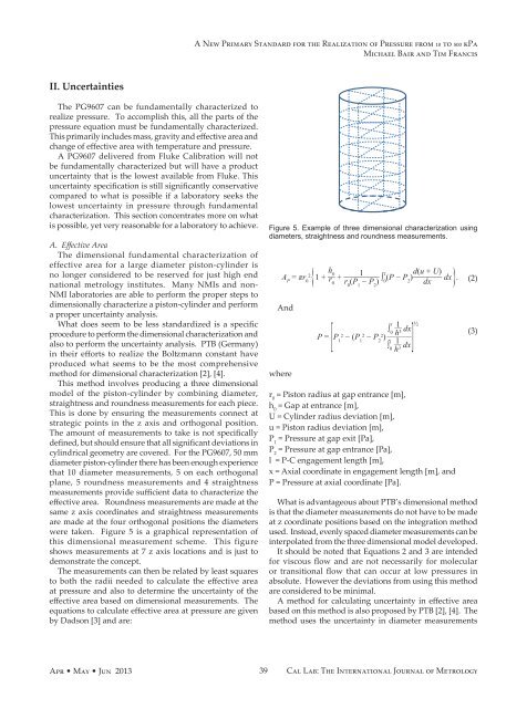
were taken. Figure 5 is a graphical representation of<br />
this dimensional measurement scheme. This figure<br />
shows measurements at 7 z axis locations and is just to<br />
demonstrate the concept.<br />
The measurements can then be related by least squares<br />
to both the radii needed to calculate the effective area<br />
at pressure and also to determine the uncertainty of the<br />
effective area based on dimensional measurements. The<br />
equations to calculate effective area at pressure are given<br />
by Dadson [3] and are:<br />
Figure 5. Example of three dimensional characterization using<br />
diameters, straightness and roundness measurements.<br />
A P<br />
= πr 2 __<br />
0 { 1 + h<br />
0 _________ 1<br />
r0<br />
+<br />
r 0<br />
(P 1<br />
− P 2<br />
) ∫ 1 ________ d(u + U)<br />
(P − P<br />
0 2<br />
) dx<br />
dx } .<br />
And<br />
where<br />
[<br />
x 1__<br />
∫ 0 <br />
P = P 1<br />
2 − ( P 1<br />
2 − P 2<br />
2 ______<br />
)<br />
h 3 dx<br />
½<br />
∫ l 0<br />
1__<br />
h 3 dx ] <br />
r 0<br />
= Piston radius at gap entrance [m],<br />
h 0<br />
= Gap at entrance [m],<br />
U = Cylinder radius deviation [m],<br />
u = Piston radius deviation [m],<br />
P 1<br />
= Pressure at gap exit [Pa],<br />
P 2<br />
= Pressure at gap entrance [Pa],<br />
l = P-C engagement length [m],<br />
x = Axial coordinate in engagement length [m], and<br />
P = Pressure at axial coordinate [Pa].<br />
What is advantageous about PTB’s dimensional method<br />
is that the diameter measurements do not have to be made<br />
at z coordinate positions based on the integration method<br />
used. Instead, evenly spaced diameter measurements can be<br />
interpolated from the three dimensional model developed.<br />
It should be noted that Equations 2 and 3 are intended<br />
for viscous flow and are not necessarily for molecular<br />
or transitional flow that can occur at low pressures in<br />
absolute. However the deviations from using this method<br />
are considered to be minimal.<br />
A method for calculating uncertainty in effective area<br />
based on this method is also proposed by PTB [2], [4]. The<br />
method uses the uncertainty in diameter measurements<br />
(2)<br />
(3)<br />
Apr • May • Jun 2013<br />
39<br />
<strong>Cal</strong> <strong>Lab</strong>: The International Journal of Metrology