Service & Repair Manual - Frogkick.dk
Service & Repair Manual - Frogkick.dk
Service & Repair Manual - Frogkick.dk

Create successful ePaper yourself
Turn your PDF publications into a flip-book with our unique Google optimized e-Paper software.
SeaAir Regulator<br />
(see Fig. 27). While holding the air barrel with the flat cut<br />
facing up, insert one leg of the lever(18) into one hole, so that<br />
it engages with the poppet (see Fig. 28). Being careful to avoid<br />
stretching or bending the lever, rotate it over the air barrel until<br />
the opposite leg engages with the opposite side. Check to ensure<br />
that the lever is properly seated on both sides, securely engaging<br />
the poppet ears. (See Fig. 29.)<br />
Fig. 28 – Lever Installation<br />
Fig. 29 – Correct Lever Orientation<br />
Fig. 30 – Poppet Alignment/ Preset Tool<br />
NOTE: To better control the orientation of the poppet<br />
inside the air barrel while the lever is being installed,<br />
XS Scuba recommends using the Poppet Align/<br />
Orifice Preset Tool (P/N 20-785-400), available from<br />
Peter Built Co. (See Fig. 30.)<br />
8. Apply a light coat of lubricant to both ends of the poppet<br />
spring(4), and place the spring inside the air barrel, over the<br />
small end of the poppet.<br />
9. Insert the small end of the shuttle cap(3) into the end of the<br />
poppet spring.<br />
10. Install the O-ring(2) onto the adjustment knob(1). Mate the<br />
adjustment knob directly over the shuttle cap, and screw the<br />
knob clockwise onto the air barrel approximately 3-4 full turns.<br />
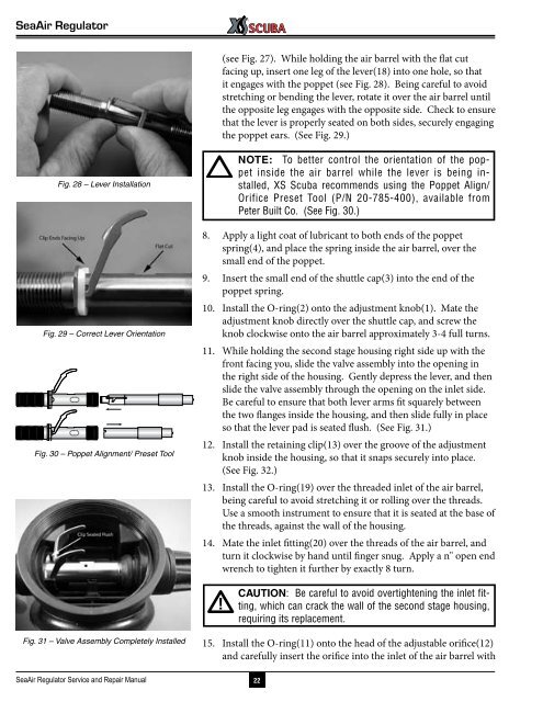
11. While holding the second stage housing right side up with the<br />
front facing you, slide the valve assembly into the opening in<br />
the right side of the housing. Gently depress the lever, and then<br />
slide the valve assembly through the opening on the inlet side.<br />
Be careful to ensure that both lever arms fit squarely between<br />
the two flanges inside the housing, and then slide fully in place<br />
so that the lever pad is seated flush. (See Fig. 31.)<br />
12. Install the retaining clip(13) over the groove of the adjustment<br />
knob inside the housing, so that it snaps securely into place.<br />
(See Fig. 32.)<br />
13. Install the O-ring(19) over the threaded inlet of the air barrel,<br />
being careful to avoid stretching it or rolling over the threads.<br />
Use a smooth instrument to ensure that it is seated at the base of<br />
the threads, against the wall of the housing.<br />
14. Mate the inlet fitting(20) over the threads of the air barrel, and<br />
turn it clockwise by hand until finger snug. Apply a n" open end<br />
wrench to tighten it further by exactly 8 turn.<br />
CAUTION: Be careful to avoid overtightening the inlet fitting,<br />
which can crack the wall of the second stage housing,<br />
requiring its replacement.<br />
Fig. 31 – Valve Assembly Completely Installed<br />
15. Install the O-ring(11) onto the head of the adjustable orifice(12)<br />
and carefully insert the orifice into the inlet of the air barrel with<br />
SeaAir Regulator <strong>Service</strong> and <strong>Repair</strong> <strong>Manual</strong><br />
22