Lithium-Ion Battery Simulation for Greener Ford Vehicles
Lithium-Ion Battery Simulation for Greener Ford Vehicles
Lithium-Ion Battery Simulation for Greener Ford Vehicles

Create successful ePaper yourself
Turn your PDF publications into a flip-book with our unique Google optimized e-Paper software.
MEDICAL<br />
HARVARD MEDICAL SCHOOL & MASSACHUSETTS GENERAL HOSPITAL, BOSTON, MA<br />
Microscopic Magnetic Field <strong>Simulation</strong>s with COMSOL Multiphysics<br />
Micro-magnetic fields hold the promise of new medical treatments. Researchers turn to modeling<br />
<strong>for</strong> designing a MEMS field generator device.<br />
BY GIORGIO BONMASSAR, HARVARD MEDICAL SCHOOL AND A.A. MARTINOS CENTER, MASSACHUSETTS GENERAL HOSPITAL<br />
Electrical stimulation is currently used<br />
as a therapeutic option <strong>for</strong> treating a<br />
wide range of human diseases including<br />
cardiovascular, sensory and neurological<br />
disorders. Despite the remarkable success<br />
of electrical stimulation, there are significant<br />
limitations to its application; these<br />
limitations include incompatibility with<br />
magnetic resonance imaging (MRI) and the<br />
association with tissue inflammation. Here,<br />
we present an alternative method that uses<br />
micro-magnetic fields instead of direct electrical<br />
currents to activate excitable tissue.<br />
MEMS Microinductor<br />
COMSOL Multiphysics allowed us to<br />
estimate microscopic magnetic fields generated<br />
by a custom made micro-coil. The<br />
field estimation was per<strong>for</strong>med using the<br />
AC/DC Module, which gives the ability to<br />
solve Maxwell equation <strong>for</strong> the description<br />
of electromagnetic fields with the magnetic<br />
quasi static approximation. This approximation<br />
holds when considering low<br />
frequencies and ignoring the contribution<br />
of the displacement<br />
currents. We<br />
studied the MEMS<br />
microinductor (Fig.<br />
1) designed to create<br />
a microscopic<br />
magnetic field using<br />
a 3D model of<br />
electromagnetic<br />
quasistatic approximation.<br />
An inductor is<br />
the ideal magnetic<br />
field generator, and<br />
it stores the magnetic<br />
field energy<br />
generated by the<br />
supplied electric<br />
current. The 3D<br />
model of the square<br />
inductor was solved<br />
<strong>for</strong> the electric and<br />
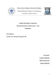
Fig. 1. Image of a μMS coil. The typical overall<br />
dimensions of the coils are 350 μm × 350 μm.<br />
magnetic potentials using the Lagrange<br />
Quadratic vector with constant input current.<br />
The geometry (Fig. 2) consisted of a<br />
680×680×400 µm block, which contained<br />
three different objects: a seven-turn coil<br />
composed of gold traces (red), surrounded<br />
by air and the tissue substrate (blue). The<br />
assumption made was that no displacement<br />
currents were present. However, a<br />
capacitive component may still have been<br />
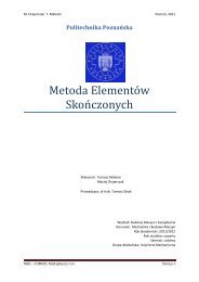
Fig. 2. Geometrical model of the 7 turns spiral square<br />
inductor (red) on top of the neuronal tissue (blue)<br />
and connected to a current generator. This model of<br />
the proposed coils was used in the Finite Element 3D<br />
studies to estimate the induced currents in the tissue<br />
(i.e., 50μm).<br />
present in our stimulation. Future studies<br />
should address this important point.<br />
Micro-Magnetic Fields <strong>Simulation</strong><br />
In setting up the model, all set the<br />
steps were per<strong>for</strong>med in COMSOL Multiphysics,<br />
including: (1) drawing, (2) defining<br />
the boundary conditions, (3) meshing,<br />
(4) solving and (5) post-processing.<br />
The drawing procedure was facilitated<br />
by the existence of a similar example in<br />
the COMSOL Model Library named “Integrated<br />
Square-Shaped Spiral Inductor”.<br />
This model examines the case of a<br />
MEMS square inductor that is used <strong>for</strong><br />
LC bandpass filters but with fewer turns<br />
than in our case. As in the example, the<br />
boundary conditions allowed <strong>for</strong> the definition<br />
of the excitation with the use of a<br />
port. The mesh was a Delaunay set with<br />
a maximum element size of 2.5 10 -5 m on<br />
the coil domain and with the adaptive refine<br />
meshing option, generating a mesh<br />
consisting of 7,782 tetrahedral base mesh<br />
elements, and 61,685 degrees of freedom.<br />
Fig. 3. Distribution of the magnetic field (arrows) generated<br />
around the μMS coil as predicted by the 3D FEM simulations.<br />
The size of the arrow is directly proportional to the magnitude of<br />
the magnetic field (A/m) in each (x, y, z) point of space uni<strong>for</strong>mly<br />
sampled in 7×7×7 locations. The colormap represents the electric<br />
potential (V).<br />
4 2 // C O M S O L N E W S 2 0 1 1<br />
➮<br />
Cov ToC + – A<br />
➭<br />
42-43 CN Harvard 2011.indd 42 5/16/11 9:29 AM