BST 14i3 - Wieland Electric
BST 14i3 - Wieland Electric
BST 14i3 - Wieland Electric

You also want an ePaper? Increase the reach of your titles
YUMPU automatically turns print PDFs into web optimized ePapers that Google loves.
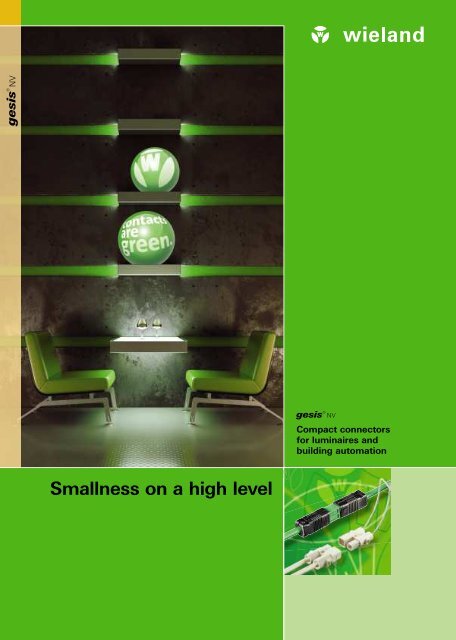
gesis ® NV<br />
gesis® NV<br />
Compact connectors<br />
for luminaires and<br />
building automation<br />
Smallness on a high level
<strong>BST</strong> ST 14i2…i3 16<br />
2 Layout-Stand 18.03.2012
ST 16…ST 17<br />
Contents<br />
Page<br />
<strong>BST</strong> 14i2/<strong>BST</strong> <strong>14i3</strong> Signal applications<br />
A beacon technology 4 – 5<br />
ST 16/ST 17 Low-voltage halogen<br />
Advanced technology for perfect light accents 6 – 7<br />
<strong>BST</strong> 14i2.<br />
Components 8 – 15<br />
<strong>BST</strong> <strong>14i3</strong>.<br />
Components 16 – 21<br />
ST 16.<br />
Components 22 – 29<br />
ST 17.<br />
Components 30 – 39<br />
Technical data 40 – 43<br />
Support, index<br />
For further information, subsidiaries 44 – 51<br />
Layout-Stand 18.03.2012<br />
3
<strong>BST</strong> 16 14i2<br />
4<br />
Layout-Stand 18.03.2012
<strong>BST</strong> <strong>14i3</strong><br />
<strong>BST</strong> 14i2/<strong>BST</strong> <strong>14i3</strong> Signal applications<br />
A beacon technology<br />
Versatile in use.<br />
Using the pluggable <strong>BST</strong> connectors you can also<br />
install signal applications. Mechanical coding and<br />
clear assignment with different colors facilitate the<br />
installation: green for KNX applications, green for<br />
KNX applications; black for general signal or LON<br />
applications; blue for dimming or DALI functions.<br />
Complex installations can be completed with just four<br />
basic components - from the distribution panel unit<br />
to any point of use. Connectors can be assembled<br />
on site and serve, for instance, for the supply of the<br />
gesis system.<br />
The connectors are supplied as male or female<br />
connectors complete with strain relief and can be<br />
used to connect any current type of cables. Device<br />
connectors allow for plug-in connection of electrical<br />
devices. They are either snapped directly into defined<br />
recesses of the housing (snap-in design), or soldered<br />
onto PC boards (solder connections).<br />
Ready-to-plug distribution boards are integrated into<br />
the installation to accommodate branch-off lines to<br />
terminal equipment. Pre-assembled cables come<br />
ready-to-use and factory-tested. They are available in<br />
a multitude of different designs.<br />
Benefits at a glance:<br />
■ Room lighting can be customized<br />
by selective dimming or by signal<br />
transmission to the home<br />
automation system, and integrated<br />
into the gesis system.<br />
Layout-Stand 18.03.2012<br />
5
ST 16 17<br />
6<br />
Layout-Stand 18.03.2012
ST 16<br />
ST 16/ST 17 Low-voltage halogen<br />
Advanced technology for perfect light accents<br />
Versatile in use.<br />
Light accents are a decisive factor in shop fitting –<br />
optimum results are achieved by low-voltage halogen<br />
installations with halogen spotlights.<br />
The gesis ST16/ST17 lines allow the implementation<br />
of the entire electrical installation in the low-voltage<br />
halogen range. The key feature of the system is its<br />
wide range of individual components, which make it<br />
versatile enough to fit any application.<br />
The connectors are mechanically coded, so that<br />
inadvertent mismating with connectors of other<br />
product lines is ruled out. A pre-assembled electronic<br />
transformer allows the direct supply of energy from<br />
the gesis CON system by a plug contact.<br />
Benefits at a glance:<br />
■ Good lighting has a positive effect on<br />
the customers’ buying behavior. The<br />
selective use of low-voltage halogen<br />
spotlights interconnected via gesis<br />
can make a decisive contribution.<br />
Layout-Stand 18.03.2012 7
8<br />
<strong>BST</strong> 14i2
<strong>BST</strong> 14i2<br />
Bus applications and transmission of analog and<br />
digital dimming signals<br />
Application example<br />
General<br />
Connectors for KNX applications have<br />
a unique mechanical coding which is<br />
visually defined by the color green.<br />
The mechanical coding “Code 2” is<br />
specially intended for the transmission<br />
of both analog and digital dimming<br />
signals.<br />
Mechanical coding means that only<br />
associated pairs of male and female<br />
connectors can be connected; correct<br />
polarity is ensured.<br />
You therefore have the security<br />
of a clear segregation of different<br />
applications, at the same time<br />
preventing any incorrect connections.<br />
The color of the connectors indicates<br />
the relevant links. If only one code<br />
differentiation is sufficient or required,<br />
you can choose between two color<br />
combinations within a coding.<br />
These connectors are then mutually<br />
compatible.<br />
Coding<br />
Mechanical<br />
coding<br />
Code 1<br />
Code 2<br />
Name<br />
Description<br />
Connection<br />
technology<br />
Strain relief<br />
housing<br />
Conn. points<br />
per pole<br />
black/<br />
green<br />
black/<br />
pastel blue<br />
Connector<br />
Spring-loaded<br />
yes<br />
1<br />
Snap in<br />
for material thickness:<br />
0.5 – 1.5 mm<br />
Spring-loaded<br />
1<br />
Solder connection 90°<br />
Lighting connections<br />
Solder pins<br />
Spring-loaded<br />
1<br />
1<br />
Distribution unit<br />
1 Input<br />
5 Outputs<br />
1 Input<br />
3 Outputs<br />
Device connection cable<br />
Male – Free end<br />
pre-assembled<br />
pre-assembled<br />
pre-assembled<br />
Cable assemblies<br />
Connection cable<br />
Female – Free end<br />
Extension cable<br />
Male – Female<br />
Please see the first pages of the Technical Data section for a table of the approximated relation between the conductor cross sections and the AWG sizes.<br />
9
<strong>BST</strong> 14i2<br />
Spring-clamp connection, snap-in 50 V, 3 A<br />
Female connector<br />
Spring clamp connection<br />
Snap-in, spring-loaded<br />
Housing cut-out<br />
Material thickness:<br />
0.5 – 1.5 mm<br />
Application Coding Color<br />
Part No.<br />
Spring clamp connection with strain relief<br />
Cable solid/<br />
0.25 – 0.75 mm<br />
fi ne-stranded<br />
2<br />
for cable diameter 1) 5.5 –6.5 mm<br />
fully assembled with strain relief and<br />
locking device<br />
Sheath strip length 21 mm<br />
Wire stripping length 9 mm<br />
Part No.<br />
Snap-in, spring-loaded<br />
Cable solid/<br />
0.25 – 0.75 mm<br />
fi ne-stranded<br />
2<br />
assembled with Locking device<br />
Housing cut-out 2) snaps into position<br />
Coding dimming Code 2<br />
with cover<br />
Wire stripping length 9 mm<br />
KNX bus<br />
2 pole<br />
Dimming<br />
2-pole<br />
1+ / 2–<br />
Code 1<br />
1+ / 2–<br />
Code 2<br />
black/<br />
green<br />
black/<br />
pastel blue<br />
Type<br />
93.421.0553.1<br />
93.421.4553.1<br />
<strong>BST</strong>14i2 F B1 Z R1<br />
93.421.0353.1<br />
93.421.4353.1<br />
<strong>BST</strong>14i2 F B1 R<br />
Male connector<br />
Spring clamp connection<br />
Snap-in, spring-loaded<br />
Housing cut-out<br />
Material thickness:<br />
0.5 – 1.5 mm<br />
Application Coding<br />
Color<br />
Part No.<br />
Part No.<br />
Spring clamp connection with strain relief<br />
Cable solid/<br />
0.25 – 0.75 mm<br />
fi ne-stranded<br />
2<br />
for cable diameter 1) 5.5 –6.5 mm<br />
fully assembled with strain relief and<br />
locking device<br />
Sheath strip length 21 mm<br />
Wire stripping length 9 mm<br />
Snap-in, spring-loaded<br />
Cable solid/<br />
0.25 – 0.75 mm<br />
fi ne-stranded<br />
2<br />
assembled with Locking device<br />
Housing cut-out 2) snaps into position<br />
Coding dimming Code 2<br />
with cover<br />
Wire stripping length 9 mm<br />
KNX bus<br />
2 pole<br />
Dimming<br />
2-pole<br />
2– / 1+<br />
Code 1<br />
2– / 1+<br />
Code 2<br />
black/<br />
green<br />
black/<br />
pastel blue<br />
Type<br />
93.422.0553.1<br />
93.422.4553.1<br />
<strong>BST</strong>14i2 F S1 Z R1<br />
93.422.0353.1<br />
93.422.4353.1<br />
<strong>BST</strong>14i2 F S1 R<br />
10<br />
1) Other cables and cross sections available on request<br />
2)<br />
Housing material, paint and deburring may influence the tight fit<br />
inside the housing.<br />
Detailed installation instructions available on request.
<strong>BST</strong> 14i2<br />
Solder connection, horizontal<br />
Accessories<br />
Female connector<br />
Solder connector,<br />
horizontal<br />
Cover<br />
for <strong>BST</strong>14i2 female connectors<br />
Application Coding Color<br />
Part No.<br />
Solder connector, horizontal<br />
PC board<br />
solder fi xation<br />
Locating pins yes<br />
Locking device yes<br />
Part No.<br />
for covering open output contacts<br />
KNX bus<br />
2 pole<br />
Dimming<br />
2-pole<br />
1+ / 2–<br />
Code 1<br />
1+ / 2–<br />
Code 2<br />
black/<br />
green<br />
black/<br />
pastel blue<br />
Type<br />
93.421.0653.1<br />
93.421.4653.1<br />
<strong>BST</strong>14i2 L B1<br />
05.563.7753.0<br />
Male connector<br />
Solder connector,<br />
horizontal<br />
Cover<br />
for <strong>BST</strong>14i2 male connectors<br />
Application Coding<br />
Color<br />
Part No.<br />
Part No.<br />
Solder connector, horizontal<br />
PC board<br />
solder fi xation<br />
Locating pins yes<br />
Locking device yes<br />
for covering open output contacts<br />
KNX bus<br />
2 pole<br />
Dimming<br />
2-pole<br />
2– / 1+<br />
Code 1<br />
2– / 1+<br />
Code 2<br />
black/<br />
green<br />
black/<br />
pastel blue<br />
Type<br />
93.422.0653.1<br />
93.422.4653.1<br />
<strong>BST</strong>14i2 L S1<br />
05.563.7853.0<br />
11
<strong>BST</strong> 14i2<br />
Distribution blocks 2 pole 50 V, 3 A<br />
Distribution unit 1I/5O<br />
without mounting option<br />
Name Color Part no.<br />
<strong>BST</strong> 14i2V 5P1 green<br />
93.420.0053.0<br />
Connection diagram<br />
with locking device<br />
Input<br />
Outputs<br />
1, male connector 2 pole<br />
5, female connector 2 pole<br />
Distribution unit 1I/3O<br />
without mounting option<br />
Name Color Part no.<br />
<strong>BST</strong> 14i2V 3P1 green<br />
93.420.0453.0<br />
Connection diagram<br />
with locking device<br />
Input<br />
Outputs<br />
1, male connector 2 pole<br />
3, female connector 2 pole<br />
Distribution block<br />
T-shaped<br />
Name Color Part no.<br />
<strong>BST</strong> 14i2V 2P1 T black/green<br />
93.420.0653.0<br />
<strong>BST</strong> 14i2V 2P1 T black/pastel blue<br />
93.420.4653.0<br />
Connection diagram<br />
with locking device<br />
Input<br />
Outputs<br />
1, male connector 2 pole<br />
2, female connector 2 pole<br />
TT distribution unit<br />
with locking device<br />
Name Color Part no.<br />
<strong>BST</strong> 14i2V 2P1 KR pastel blue<br />
93.420.4553.0<br />
with locking device<br />
Input<br />
1, male connector 2 pole<br />
Output<br />
1, female connector 2 pole<br />
Federkraftklemme integrated for solid 2 x 0.75 mm 2<br />
Cover<br />
included<br />
Sheath strip length<br />
23 mm<br />
Wire stripping length 9 mm<br />
wires p. pole, snaps into position<br />
12
<strong>BST</strong> 14i2<br />
Cable assemblies 50 V, 3 A<br />
FB-2Y(ST)2Y 2x(2x0.8)<br />
Insulation:<br />
contains halogen 2)<br />
KNX bus<br />
Bus pluggable connectors<br />
as per KNX<br />
– Requirements as per KNX manual<br />
– Required for pluggable<br />
KNX applications<br />
– Identifi ed by green contact zone<br />
– Coding accord. to KNX standard<br />
– with integrated latch<br />
– Green cable,<br />
cross section: 0.5 mm 2<br />
– KNX-certifi ed<br />
Cable 1)<br />
Color green<br />
KNX bus<br />
2 pole<br />
1+ = red<br />
2–= black<br />
Code 1<br />
1+ / 2–<br />
2– / 1+<br />
black/<br />
green<br />
Cable<br />
green<br />
Standard cable type FB-2Y(ST)2Y 2x(2x0.8)<br />
Extension cable<br />
KNX bus<br />
2 x 0.5 mm 2<br />
Female – Male<br />
94.425.1000.7<br />
94.425.2000.7<br />
94.425.3000.7<br />
94.425.4000.7<br />
94.425.5000.7<br />
94.425.6000.7<br />
94.425.7000.7<br />
94.425.8000.7<br />
Connection cable<br />
KNX bus<br />
2 x 0.5 mm 2<br />
Female – Free end 3)<br />
Application Coding Color Length 1) Part No. Part No. Part No.<br />
1.0 m<br />
2.0 m<br />
3.0 m<br />
4.0 m<br />
5.0 m<br />
6.0 m<br />
7.0 m<br />
8.0 m<br />
94.425.1003.7<br />
94.425.2003.7<br />
94.425.3003.7<br />
94.425.4003.7<br />
94.425.5003.7<br />
94.425.6003.7<br />
94.425.7003.7<br />
94.425.8003.7<br />
Connection cable<br />
KNX bus<br />
2 x 0.5 mm 2<br />
Male – Free end 3)<br />
94.425.1004.7<br />
94.425.2004.7<br />
94.425.3004.7<br />
94.425.4004.7<br />
94.425.5004.7<br />
94.425.6004.7<br />
94.425.7004.7<br />
94.425.8004.7<br />
Type<br />
<strong>BST</strong>14i2 KF BS<br />
<strong>BST</strong>14i2 KF B<br />
<strong>BST</strong>14i2 KF S<br />
1) Other lengths, cables available on request<br />
2) Halogen-free on request<br />
3) Other sheath and insulation strip lengths<br />
available on request<br />
13
<strong>BST</strong> 14i2<br />
Cable assemblies 50 V, 3 A<br />
L03VV-U2x0.5 1)<br />
Insulation:<br />
contains halogen<br />
Dimming applications<br />
1+ = red<br />
2–= black<br />
Dimming connector for dimming<br />
applications<br />
– Identifi ed by pastel blue contact zone<br />
– Black cable, cross section: 0.5 mm 2<br />
– Please observe the notes in the<br />
Technical Data section<br />
Standard cable type L03VV-U2x0.5<br />
Extension cable<br />
2 x 0.5 mm 2<br />
Female – Male<br />
Connection cable<br />
2 x 0.5 mm 2<br />
Female – Free end 2)<br />
Connection cable<br />
2 x 0.5 mm 2<br />
Male – Free end 2)<br />
Application Coding Color Length 1) Part No. Part No. Part No.<br />
Dimming<br />
2 pole<br />
Code 2<br />
1+ / 2–<br />
2– / 1+<br />
black/<br />
pastel blue<br />
Cable<br />
black<br />
1.0 m<br />
2.0 m<br />
3.0 m<br />
4.0 m<br />
5.0 m<br />
6.0 m<br />
7.0 m<br />
8.0 m<br />
94.425.1030.9<br />
94.425.2030.9<br />
94.425.3030.9<br />
94.425.4030.9<br />
94.425.5030.9<br />
94.425.6030.9<br />
94.425.7030.9<br />
94.425.8030.9<br />
94.425.1033.9<br />
94.425.2033.9<br />
94.425.3033.9<br />
94.425.4033.9<br />
94.425.5033.9<br />
94.425.6033.9<br />
94.425.7033.9<br />
94.425.8033.9<br />
94.425.1034.9<br />
94.425.2034.9<br />
94.425.3034.9<br />
94.425.4034.9<br />
94.425.5034.9<br />
94.425.6034.9<br />
94.425.7034.9<br />
94.425.8034.9<br />
Type<br />
<strong>BST</strong>14i2 KF BS<br />
<strong>BST</strong>14i2 KF B<br />
<strong>BST</strong>14i2 KF S<br />
14<br />
1) Other lengths, cables available on request<br />
2) Other sheath and insulation strip lengths<br />
available on request
<strong>BST</strong> 14i2<br />
Cable assemblies 50 V, 3 A<br />
L03Z1Z1-U2x0.5 1)<br />
Insulation:<br />
halogen-free<br />
Dimming applications<br />
1+ = red<br />
2–= black<br />
Dimming connector for dimming<br />
applications<br />
– Identifi ed by pastel blue contact zone<br />
– Black cable, cross section: 0.5 mm 2<br />
– Please observe the notes in the<br />
Technical Data section<br />
Standard cable type L03Z1Z1-U2x0.5<br />
Extension cable<br />
2 x 0.5 mm 2<br />
Female – Male<br />
Connection cable<br />
2 x 0.5 mm 2<br />
Female – Free end 2)<br />
Connection cable<br />
2 x 0.5 mm 2<br />
Male – Free end 2)<br />
Application Coding Color Length 1) Part No. Part No. Part No.<br />
Dimming<br />
2 pole<br />
Code 2<br />
1+ / 2–<br />
2– / 1+<br />
black/<br />
pastel blue<br />
Cable<br />
black<br />
1.0 m<br />
2.0 m<br />
3.0 m<br />
4.0 m<br />
5.0 m<br />
6.0 m<br />
7.0 m<br />
8.0 m<br />
94.425.1090.9<br />
94.425.2090.9<br />
94.425.3090.9<br />
94.425.4090.9<br />
94.425.5090.9<br />
94.425.6090.9<br />
94.425.7090.9<br />
94.425.8090.9<br />
94.425.1093.9<br />
94.425.2093.9<br />
94.425.3093.9<br />
94.425.4093.9<br />
94.425.5093.9<br />
94.425.6093.9<br />
94.425.7093.9<br />
94.425.8093.9<br />
94.425.1094.9<br />
94.425.2094.9<br />
94.425.3094.9<br />
94.425.4094.9<br />
94.425.5094.9<br />
94.425.6094.9<br />
94.425.7094.9<br />
94.425.8094.9<br />
Type<br />
<strong>BST</strong>14i2 KF BS<br />
<strong>BST</strong>14i2 KF B<br />
<strong>BST</strong>14i2 KF S<br />
1) Other lengths, cables available on request<br />
2) Other sheath and insulation strip lengths<br />
available on request<br />
15
16<br />
<strong>BST</strong> <strong>14i3</strong>
<strong>BST</strong> <strong>14i3</strong><br />
Connectors for the transmission of bus and control signals<br />
Application example<br />
General<br />
These connectors are designed for<br />
the transmission of bus or control<br />
signals and are mechanically coded<br />
accordingly.<br />
Mechanically coded means that<br />
only the matching male and female<br />
connectors can be plugged together;<br />
correct polarity is ensured.<br />
You can therefore be sure not to<br />
confuse them with connectors of other<br />
lines, which allows a clear distinction of<br />
different applications.<br />
The color of the connectors indicates<br />
the relevant links. Within a mechanical<br />
coding, all color combinations can be<br />
connected.<br />
Coding<br />
Application<br />
Mechanical<br />
coding<br />
Bus and control signals<br />
3 pole<br />
Code 3<br />
Name<br />
Description<br />
Connection<br />
technology<br />
Strain relief<br />
housing<br />
Points per pole<br />
black<br />
white<br />
Connector<br />
Spring<br />
yes<br />
1<br />
Snap in<br />
Solder<br />
connection<br />
Distribution<br />
unit<br />
Cable<br />
assemblies<br />
for material thickness:<br />
0.5-1.5 mm<br />
90°<br />
1 Input<br />
5 Outputs<br />
1 Input<br />
3 Outputs<br />
Device connection cable<br />
Male – Free end<br />
Connection cable<br />
Female – Free end<br />
Extension cable<br />
Male – Female<br />
Spring 1<br />
Solder pins<br />
pre-assembled<br />
pre-assembled<br />
1<br />
pre-assembled<br />
Please see the first pages of the Technical Data section for a table of the approximated relation between the conductor cross sections and the AWG sizes.<br />
17
<strong>BST</strong> <strong>14i3</strong><br />
Spring clamp connection, snap-in 50 V, 3 A<br />
Female connector<br />
Spring clamp connection<br />
Snap-in, spring-loaded<br />
Housing cut-out<br />
Material thickness:<br />
0.5 – 1.5 mm<br />
Application Coding Color<br />
Part No.<br />
Spring clamp connection with strain relief<br />
Cable solid/<br />
0.25 – 0.75 mm<br />
fi ne-stranded<br />
2<br />
for cable diameter 1) 5.5 –6.5 mm<br />
fully assembled with strain relief and<br />
locking device<br />
Sheath strip length 21 mm<br />
Wire stripping length 9 mm<br />
Part No.<br />
Snap-in, spring-loaded<br />
Cable solid/<br />
0.25 – 0.75 mm<br />
fi ne-stranded<br />
2<br />
assembled with Locking device<br />
Housing cut-out 2) snaps into position<br />
Wire stripping length 9 mm<br />
Bus and<br />
control signals<br />
2 pole + screen<br />
1+ / 2–<br />
Code 3<br />
black<br />
white<br />
Type<br />
93.431.2553.1<br />
93.431.2553.0<br />
<strong>BST</strong><strong>14i3</strong> F B1 Z R1<br />
93.431.2353.1<br />
93.431.2353.0<br />
<strong>BST</strong><strong>14i3</strong> F B1 R<br />
Male connector<br />
Spring clamp connection<br />
Snap-in, spring-loaded<br />
Housing cut-out<br />
Material thickness:<br />
0.5 – 1.5 mm<br />
Application Coding<br />
Color<br />
Part No.<br />
Part No.<br />
Spring clamp connection with strain relief<br />
Cable solid/<br />
0.25 – 0.75 mm<br />
fi ne-stranded<br />
2<br />
for cable diameter 1) 5.5 –6.5 mm<br />
fully assembled with strain relief and<br />
locking device<br />
Sheath strip length 21 mm<br />
Wire stripping length 9 mm<br />
Snap-in, spring-loaded<br />
Cable solid/<br />
0.25 – 0.75 mm<br />
fi ne-stranded<br />
2<br />
assembled with Locking device<br />
Housing cut-out 2) snaps into position<br />
Wire stripping length 9 mm<br />
Bus and<br />
control signals<br />
2 pole + screen<br />
2– / 1+<br />
Code 3<br />
black<br />
white<br />
Type<br />
93.432.2553.1<br />
93.432.2553.0<br />
<strong>BST</strong><strong>14i3</strong> F S1 Z R1<br />
93.432.2353.1<br />
93.432.2353.0<br />
<strong>BST</strong><strong>14i3</strong> F S1 R<br />
18<br />
1) Other cables and cross sections available on request<br />
2)<br />
Housing material, paint and deburring may influence the tight fit<br />
inside the housing.<br />
Detailed installation instructions available on request.
<strong>BST</strong> <strong>14i3</strong><br />
Solder connector, horizontal<br />
Accessories<br />
Female connector<br />
Solder connector,<br />
horizontal<br />
Cover<br />
for <strong>BST</strong><strong>14i3</strong> female connectors<br />
Application Coding Color<br />
Part No.<br />
Solder connector, horizontal<br />
PC board<br />
solder fi xation<br />
Locating pins yes<br />
Locking device yes<br />
Part No.<br />
for covering open output contacts<br />
Bus and<br />
control signals<br />
2 pole + screen<br />
1+ / 2–<br />
Code 3<br />
black<br />
white<br />
Type<br />
93.431.2653.1<br />
93.431.2653.0<br />
<strong>BST</strong><strong>14i3</strong> L B1<br />
05.563.7753.0<br />
Male connector<br />
Solder connector,<br />
horizontal<br />
Cover<br />
for <strong>BST</strong><strong>14i3</strong> male connectors<br />
Application Coding<br />
Color<br />
Part No.<br />
Part No.<br />
Solder connector, horizontal<br />
PC board<br />
solder fi xation<br />
Locating pins yes<br />
Locking device yes<br />
for covering open output contacts<br />
Bus and<br />
control signals<br />
2 pole + screen<br />
2– / 1+<br />
Code 3<br />
black<br />
white<br />
Type<br />
93.432.2653.1<br />
93.432.2653.0<br />
<strong>BST</strong><strong>14i3</strong> L S1<br />
05.563.7853.0<br />
19
<strong>BST</strong> <strong>14i3</strong><br />
Distribution blocks 3 pole 50 V, 3 A<br />
Distribution unit 1I/5O<br />
without mounting option<br />
Name Color Part no.<br />
<strong>BST</strong> <strong>14i3</strong>V 5P1 black<br />
93.430.2053.1<br />
<strong>BST</strong> <strong>14i3</strong>V 5P1 white<br />
93.430.2053.0<br />
Connection diagram<br />
with locking device<br />
Input<br />
Outputs<br />
1, male connector 3 pole<br />
5, female connector 3 pole<br />
Distribution unit 1I/3O<br />
without mounting option<br />
Name Color Part no.<br />
<strong>BST</strong> <strong>14i3</strong>V 3P1 black<br />
93.430.2453.1<br />
<strong>BST</strong> <strong>14i3</strong>V 3P1 white<br />
93.430.2453.0<br />
Connection diagram<br />
with locking device<br />
Input<br />
Outputs<br />
1, male connector 3 pole<br />
3, female connector 3 pole<br />
Distribution block<br />
T-shaped<br />
Name Color Part no.<br />
<strong>BST</strong> <strong>14i3</strong>V 2P1 T black<br />
93.430.2653.1<br />
<strong>BST</strong> <strong>14i3</strong>V 2P1 T white<br />
93.430.2653.0<br />
Connection diagram<br />
with locking device<br />
Input<br />
Outputs<br />
1, male connector 3 pole<br />
2, female connector 3 pole<br />
20
<strong>BST</strong> <strong>14i3</strong><br />
Cable assemblies 50 V, 3 A<br />
FB-2Y(ST)2Y 2x(2x0.8) 1)<br />
Insulation:<br />
contains halogen 2)<br />
Signal connector<br />
– Identifi ed by black contact zone<br />
– with integrated latch<br />
– Cable gray<br />
1+ = red<br />
2–= black<br />
Center contact =<br />
screen<br />
Standard cable type FB-2Y(ST)2Y 2x(2x0.8)<br />
Extension cable<br />
+ screen<br />
2 x 0.5 mm 2<br />
Female – Male<br />
Connection cable<br />
+ screen<br />
2 x 0.5 mm 2<br />
Female – Free end 3)<br />
Connection cable<br />
+ screen<br />
2 x 0.5 mm 2<br />
Male – Free end 3)<br />
Application Coding Color Length 1) Part No. Part No. Part No.<br />
Bus and<br />
control<br />
signals<br />
2 pole +<br />
screen<br />
Code 3<br />
1+ / 2–<br />
2– / 1+<br />
black<br />
Cable<br />
gray<br />
1.0 m<br />
2.0 m<br />
3.0 m<br />
4.0 m<br />
5.0 m<br />
6.0 m<br />
7.0 m<br />
8.0 m<br />
94.435.1000.1<br />
94.435.2000.1<br />
94.435.3000.1<br />
94.435.4000.1<br />
94.435.5000.1<br />
94.435.6000.1<br />
94.435.7000.1<br />
94.435.8000.1<br />
94.435.1003.1<br />
94.435.2003.1<br />
94.435.3003.1<br />
94.435.4003.1<br />
94.435.5003.1<br />
94.435.6003.1<br />
94.435.7003.1<br />
94.435.8003.1<br />
94.435.1004.1<br />
94.435.2004.1<br />
94.435.3004.1<br />
94.435.4004.1<br />
94.435.5004.1<br />
94.435.6004.1<br />
94.435.7004.1<br />
94.435.8004.1<br />
Type<br />
<strong>BST</strong><strong>14i3</strong> 3KF BS<br />
<strong>BST</strong><strong>14i3</strong> 3KF B<br />
<strong>BST</strong><strong>14i3</strong> 3KF S<br />
1) Other lengths, cables available on request<br />
2) Halogen-free on request<br />
3) Other sheath and insulation strip lengths<br />
available on request<br />
21
22<br />
ST 16
ST 16<br />
Minimum space required for perfect wiring of LV systems<br />
Application example<br />
General<br />
ST 16 is the product line for wiring<br />
LV luminaires. Every single element<br />
combines female and male connectors,<br />
so that the ST 16 system is reduced to<br />
only a few basic elements. With their<br />
compact design, these connectors<br />
offer a high degree of installation<br />
convenience and at the same time<br />
require minimum space.<br />
Furthermore, the pre-assembled<br />
electronic transformer lets you directly<br />
plug the supply from the GST 18i5 line<br />
(power, 3 pole).<br />
Coding<br />
Name<br />
Connector<br />
Description<br />
Connection<br />
technology<br />
Screw 1<br />
Application<br />
Conn. points<br />
per pole<br />
Low voltage<br />
2 pole<br />
white<br />
Distribution<br />
unit<br />
1 input, 5 outputs<br />
Connector – free end<br />
Cable<br />
assemblies<br />
Electronic<br />
transformer<br />
Connector – both ends<br />
Connector – free end<br />
with fuse box<br />
pre-assembled pre-assembled<br />
Connector – both ends<br />
with fuse box<br />
Primary: Connector 1xGST 18i3<br />
Secondary: Connection cable ST 16<br />
Primary: Terminal strip<br />
Secondary: Connection cable ST 16<br />
Screw 2<br />
23
ST 16<br />
Low-voltage halogen 2 pole, 48 V, 25 A<br />
Electronic transformer<br />
Application Coding Color<br />
Part No.<br />
Primary side pluggable with GST18i3<br />
Rated voltage<br />
230 V AC 50/60 Hz<br />
Power range<br />
35 – 105 W<br />
Primary current<br />
0.45 A<br />
Ambient temperature t a<br />
max. 50° C at maximum load<br />
Secondary cable max. 2 m, min. 1.5 mm 2<br />
Installation height<br />
18 mm<br />
Connection pluggable primary side GST 18i 3 pole<br />
white<br />
Type<br />
99.448.9999.9<br />
Electronic transformer<br />
Application Coding<br />
Color<br />
Part No.<br />
Primary side clampable with screw connection (N, N, L, L)<br />
Rated voltage<br />
230 V AC 50/60 Hz<br />
Power range<br />
35 – 105 W<br />
Primary current<br />
0.45 A<br />
Ambient temperature t a<br />
max. 50° C at maximum load<br />
Secondary cable max. 2 m, min. 1.5 mm 2<br />
Installation height<br />
18 mm<br />
Connection clampable screw connection<br />
white<br />
Type<br />
99.450.9999.9<br />
24
ST 16<br />
Low-voltage halogen 2 pole, 48 V, 25 A<br />
Screw connection<br />
without strain relief<br />
Name Color Part no.<br />
ST16/2 BS white<br />
93.016.0053.0<br />
without strain relief<br />
Cables 0.5 – 2.5 mm 2 1)<br />
Locking device<br />
integrated in housing<br />
Distribution unit<br />
pluggable<br />
Name Color Part no.<br />
ST 16/2 VT 5/1 P white<br />
93.010.0153.0<br />
with locking device, pluggable, without mounting option<br />
Input 1<br />
Outputs 5<br />
Blade-type fuse<br />
Name Color Part no.<br />
Blade-type fuse 3.0 A<br />
Blade-type fuse 5.0 A<br />
Blade-type fuse 10.0 A<br />
Blade-type fuse 15.0 A<br />
purple<br />
light brown<br />
red<br />
light blue<br />
Z8.000.0175.5<br />
Z8.000.0175.7<br />
Z8.000.0175.9<br />
Z8.000.0176.0<br />
Blade-type fuses Type C according to DIN 72581 part 3<br />
1) 2.5 mm 2 : only with <strong>Wieland</strong> ferrules (see Connection cable)<br />
25
ST 16<br />
Cable assemblies 48 V, 25 A<br />
2 x 2.5 mm 2<br />
Female – male<br />
Extension cable<br />
Locking device<br />
yes<br />
Connector – Free end<br />
Connection cable<br />
Wire ends<br />
Locking device<br />
with ferrules<br />
yes<br />
Cable 1)<br />
Color white<br />
Application Length 2) m<br />
Power<br />
with<br />
g<br />
0.35<br />
0.60<br />
1.20<br />
1.80<br />
2.40<br />
Type<br />
Part No.<br />
94.623.0031.2<br />
94.623.0631.2<br />
94.623.1231.2<br />
94.623.1831.2<br />
94.623.2431.2<br />
ST 16/2 BSK1BS<br />
94.623.0032.2<br />
94.623.0632.2<br />
94.623.1232.2<br />
94.623.1832.2<br />
94.623.2432.2<br />
ST 16/2 BSK1–<br />
1) Other cables available on request<br />
2) Other lengths available on request<br />
26
ST 16<br />
Cable assemblies 48 V, 25 A<br />
2 x 2.5 mm 2<br />
Cable 1)<br />
Color white<br />
Application Length 2) m<br />
Female – male<br />
Extension cable<br />
Locking device<br />
Fuse box 3)<br />
Part No.<br />
yes<br />
yes<br />
Connector – Free end<br />
Connection cable<br />
Wire ends<br />
Locking device<br />
Fuse box 3)<br />
with ferrules<br />
yes<br />
yes<br />
Power<br />
with<br />
g<br />
0.35<br />
0.60<br />
1.20<br />
1.80<br />
2.40<br />
94.603.0031.2<br />
94.603.0631.2<br />
94.603.1231.2<br />
94.603.1831.2<br />
94.603.1232.2<br />
94.603.1832.2<br />
Type<br />
ST 16/2 BSK1SiBS<br />
ST 16/2 BSK1Si–<br />
1) Other cables available on request<br />
2) Other lengths available on request<br />
3) Blade-type fuses Type C according to DIN 72581 part 3<br />
maximum power loss of the blade-Type fuse 2.5 W, for<br />
<strong>Wieland</strong> fuses max. I N<br />
= 15 A separately available<br />
27
ST 16<br />
Cable assemblies 48 V, 6 A<br />
2 x 0.75 mm 2<br />
Cable 1) Silicone<br />
Color white<br />
Connector white<br />
Application Length 2) m<br />
Power<br />
with<br />
g<br />
0.1<br />
0.3<br />
1.0<br />
1.2<br />
2.0<br />
Connector – low-voltage halogen base GX 5.3<br />
Connection cable<br />
Temperature range max. 180 °C<br />
Retaining spring, additional GU 5.3 on request<br />
Part No.<br />
99.460.9999.9<br />
99.461.9999.9<br />
99.464.9999.9<br />
99.465.9999.9<br />
99.469.9999.9<br />
28
ST 16<br />
29
30<br />
ST 17
ST 17<br />
Consistent wiring for low-voltage halogen,<br />
versatile for any area of application<br />
Application example<br />
General<br />
ST 17 connectors enable consistent<br />
electrical installation for low-voltage<br />
applications. The system features a<br />
wide range of components and is so<br />
versatile it can be used in any kind<br />
of application. The connectors are<br />
mechanically coded and thus cannot<br />
be confused with connectors of other<br />
lines. Furthermore, the pre-assembled<br />
electronic transformer lets you directly<br />
plug the supply from the GST 18i5 line<br />
(power, 3 pole).<br />
Coding<br />
Application<br />
Low-voltage 2 pole<br />
Name<br />
Description<br />
Connection<br />
technology<br />
Strain relief<br />
housing<br />
Conn. points<br />
per pole<br />
white<br />
black<br />
Connector<br />
Screw<br />
yes<br />
1<br />
Snap in<br />
Solder<br />
connection<br />
For material thickness:<br />
0.5 – 1.5 mm<br />
90°<br />
Spring<br />
Solder pins<br />
2<br />
1<br />
1 input, 3 outputs<br />
Distribution<br />
unit<br />
1 input, 5 outputs<br />
1 input, 3 outputs<br />
with integrated fuses<br />
Male – Free end<br />
pre-assembled<br />
pre-assembled<br />
pre-assembled<br />
Cable<br />
assemblies<br />
Female – Free end<br />
Female – Male<br />
Electronic<br />
transformer<br />
Primary: connector 1xGST 18i3<br />
Secondary: connection cable ST 17<br />
Primary: terminal strip<br />
Secondary: connection cable ST 17<br />
Screw<br />
yes<br />
2<br />
31
ST 17<br />
Compact connector for LV halogen luminaires,<br />
50 V, 16 A<br />
Female connector<br />
Note:<br />
One connection point will be lost<br />
when these parts are plugged into<br />
the distribution unit.<br />
Application<br />
Color<br />
Part No.<br />
Part No.<br />
Screw connection with strain relief<br />
Cable solid/fi nestranded<br />
up to<br />
2 2.5 mm<br />
Connection per pole 1, unassembled<br />
lockable<br />
Cable diameter 5.5 – 7.0 mm, lockable<br />
Screw connection with strain relief<br />
Cable solid/fi nestranded<br />
up to<br />
2 6.0 mm<br />
Connection per pole 1, unassembled<br />
lockable<br />
Cable diameter 11.5 – 13.5 mm<br />
Low voltage<br />
2 pole<br />
black<br />
white<br />
93.941.0558.1<br />
93.941.0558.0<br />
93.941.4158.1<br />
93.941.4158.0<br />
Type<br />
ST17/2 B1 ZE V1<br />
ST17/2 B1 QZE V1<br />
Male connector<br />
with locking device<br />
Note:<br />
One connection point will be lost<br />
when these parts are plugged into<br />
the distribution unit.<br />
With locking device.<br />
Application<br />
Color<br />
Part No.<br />
Part No.<br />
Screw connection with strain relief<br />
Cable solid/fi nestranded<br />
up to<br />
2 2.5 mm<br />
Connection per pole 1, unassembled<br />
lockable<br />
Cable diameter 5.5 – 7.0 mm<br />
Screw connection with strain relief<br />
Cable solid/fi nestranded<br />
up to<br />
2 6.0 mm<br />
Connection per pole 1, unassembled<br />
lockable<br />
Cable diameter 11.5 – 13.5 mm<br />
Low voltage<br />
2 pole<br />
black<br />
white<br />
93.942.0558.1<br />
93.942.0558.0<br />
93.942.4158.1<br />
93.942.4158.0<br />
Type<br />
ST17/2 S ZE V1<br />
ST17/2 S QZE V1<br />
32
ST 17<br />
Snap-in and solder connection 50 V, 16 A<br />
Female connector<br />
Housing cut-out<br />
Application<br />
Color<br />
Part No.<br />
Part No.<br />
Snap-in, screwless<br />
Material thickness 0.5 – 1.5 mm<br />
rigid 0.5 – 2.5 mm 2<br />
fi ne-stranded 0.5 – 1.5 mm 2 ,<br />
with ferrules<br />
Housing cut-out 1) snaps into position<br />
Connection per pole 2, screwless<br />
lockable<br />
Solder connector, horizontal<br />
PC board<br />
solder fi xation<br />
Locating pins yes<br />
Low voltage<br />
2 pole<br />
black<br />
white<br />
93.041.0253.0<br />
93.041.0258.0<br />
93.081.1558.1<br />
93.081.1558.0<br />
Type<br />
ST17/2 BR<br />
ST17/2 BF V1<br />
Male connector<br />
with locking device<br />
Housing cut-out<br />
Application<br />
Color<br />
Part No.<br />
Part No.<br />
Snap-in, screwless<br />
Material thickness 0.5 – 1.5 mm<br />
rigid 0.5 – 2.5 mm 2<br />
fi ne-stranded 0.5 – 1.5 mm 2 ,<br />
with ferrules<br />
Housing cut-out 1) snaps into position<br />
Connection per pole 2, screwless<br />
lockable<br />
Solder connector, horizontal<br />
PC board<br />
solder fi xation<br />
Locking device 2) yes<br />
Locating pins yes<br />
Low voltage<br />
2 pole<br />
black<br />
white<br />
93.042.0253.0<br />
93.042.0258.0<br />
93.082.1558.1<br />
93.082.1558.0<br />
Type<br />
ST17/2 SR<br />
ST17/2 SF V1<br />
1) Housing material, paint and deburring may influence<br />
the tight fit inside the housing.<br />
33
ST 17<br />
Distribution blocks 50 V, 16 A<br />
Distribution unit 1I/3O<br />
without mounting option<br />
Name Color Part no.<br />
ST 17/2 VT 3/1 black<br />
93.040.1353.1<br />
ST 17/2 VT 3/1 white<br />
93.040.1353.0<br />
Connection diagram<br />
with locking device<br />
Input<br />
Outputs<br />
1, male connector<br />
3, female connector<br />
Distribution unit 1I/3O<br />
with mounting option<br />
Name Color Part no.<br />
ST 17/2 VT 3/1 F black<br />
93.040.1253.1<br />
ST 17/2 VT 3/1 F white<br />
93.040.1253.0<br />
Connection diagram<br />
with locking device<br />
Input<br />
Outputs<br />
1, male connector<br />
3, female connector<br />
Distribution unit 1I/5O<br />
without mounting option<br />
Name Color Part no.<br />
ST17/2 VT 5/1 black<br />
93.040.1153.1<br />
ST17/2 VT 5/1 white<br />
93.040.1153.0<br />
Connection diagram<br />
with locking device<br />
Input<br />
Outputs<br />
1, male connector<br />
5, female connector<br />
Distribution unit 1I/5O<br />
with mounting option<br />
Name Color Part no.<br />
ST17/2 VT 5/1 F black<br />
93.040.1053.1<br />
ST17/2 VT 5/1 F white<br />
93.040.1053.0<br />
Connection diagram<br />
with locking device<br />
Input<br />
Outputs<br />
1, male connector<br />
5, female connector<br />
34
ST 17<br />
Distribution unit and accessories<br />
Distribution unit<br />
with integrated fuses<br />
Name Color Part no.<br />
ST17/2 VT 3/1 SI white<br />
93.040.2050.0<br />
Order blade-type fuses Type C<br />
according to DIN 72581 part 3<br />
separately.<br />
Connection diagram<br />
with locking device<br />
Input<br />
Outputs<br />
1, male connector<br />
3, female connector<br />
Blade-type fuses Type C<br />
according to DIN 72581 part 3<br />
Name Color Part no.<br />
Blade-type fuse<br />
Blade-type fuse<br />
Blade-type fuse<br />
Blade-type fuse<br />
Blade-type fuse<br />
Blade-type fuse<br />
3 A 35 W Z8.000.0175.5<br />
5 A 50 W Z8.000.0175.7<br />
10 A 100 W Z8.000.0175.9<br />
15 A 150 W Z8.000.0176.0<br />
20 A 100 W Z8.000.0202.8<br />
25 A 150 W Z8.000.0202.9<br />
Intermediate coupling<br />
for direct routing<br />
Name Color Part no.<br />
ST 17/2 ZK 1/1 black<br />
93.040.0253.0<br />
Distribution box GST18i3V 3P1<br />
white<br />
93.040.0258.0<br />
Cover<br />
for female connector<br />
Name Color Part no.<br />
ST 17/2 BVS<br />
ST 17/2 BVS<br />
black<br />
white<br />
Z5.586.4653.1<br />
Z5.586.4653.0<br />
35
ST 17<br />
Low-voltage halogen 2 pole, 50 V, 16 A<br />
Electronic transformer<br />
Application Coding Color<br />
Part No.<br />
Primary side pluggable with GST18i3<br />
Rated voltage<br />
230 V AC 50/60 Hz<br />
Power range<br />
35 – 105 W<br />
Primary current<br />
0.45 A<br />
Ambient temperature t a<br />
max. 50° C at maximum load<br />
Secondary cable max. 2 m, min. 1.5 mm 2<br />
Installation height<br />
18 mm<br />
Connection pluggable primary side GST18i 3 pole<br />
white<br />
Type<br />
99.449.9999.9<br />
Electronic transformer<br />
Application Coding Color<br />
Part No.<br />
Primary side clampable with screw connection (N, N, L, L)<br />
Rated voltage<br />
230 V AC 50/60 Hz<br />
Power range<br />
35 – 105 W<br />
Primary current<br />
0.45 A<br />
Ambient temperature t a<br />
max. 50° C at maximum load<br />
Secondary cable max. 2 m, min. 1.5 mm 2<br />
Installation height<br />
18 mm<br />
Connection clampable screw connection<br />
white<br />
Type<br />
99.401.9999.9<br />
36
ST 17<br />
LV halogen luminaires, 2 pole, 6 A<br />
2 x 0.75 mm 2<br />
Cable 1) Silicone<br />
Color white<br />
Connector white<br />
Application Length 2) m<br />
0.1<br />
1.0<br />
1.6<br />
2.0<br />
Connector – low-voltage halogen base GX 5.3<br />
Connection cable<br />
Temperature range max. 180° C<br />
Retaining spring, GU 5.3 on request<br />
additional<br />
Part No.<br />
99.470.9999.9<br />
99.474.9999.9<br />
99.477.9999.9<br />
99.479.9999.9<br />
37
ST 17<br />
Cable assemblies 50 V, 16 A<br />
H05VV-F 1)<br />
Insulation:<br />
contains halogen (PVC)<br />
2 G 1.5 mm 2<br />
2 G 2.5 mm 2<br />
Extension cable<br />
2 G 1.5 mm 2<br />
2 G 2.5 mm 2<br />
Female – Male<br />
Locking device possible<br />
94.122.0500.1<br />
94.122.0800.1<br />
94.122.1000.1<br />
94.122.1500.1<br />
94.122.2000.1<br />
94.122.2500.1<br />
94.122.3000.1<br />
94.122.3500.1<br />
94.122.4000.1<br />
94.122.5000.1<br />
94.122.6000.1<br />
94.122.7000.1<br />
Connection cable<br />
2 G 1.5 mm 2<br />
2 G 2.5 mm 2<br />
Female – Free end<br />
Wire ends 1) ultrason. welded<br />
Locking device possible<br />
Application Coding Color Length m 2) Part No. Part No. Part No.<br />
Low voltage<br />
2 pole<br />
2 G 1.5<br />
black<br />
Cable<br />
black<br />
0.2<br />
0.3<br />
0.5<br />
0.8<br />
1.0<br />
1.5<br />
2.0<br />
2.5<br />
3.0<br />
3.5<br />
4.0<br />
5.0<br />
6.0<br />
7.0<br />
8.0<br />
94.122.0203.1<br />
94.122.0303.1<br />
94.122.0503.1<br />
94.122.1003.1<br />
94.122.1503.1<br />
94.122.2003.1<br />
94.122.2503.1<br />
94.122.3003.1<br />
94.122.4003.1<br />
94.122.6003.1<br />
94.122.7003.1<br />
Connection cable<br />
2 G 1.5 mm 2<br />
2 G 2.5 mm 2<br />
Male – Free end<br />
Wire ends 1) ultrason. welded<br />
Locking device possible<br />
94.122.0304.1<br />
94.122.0504.1<br />
94.122.1004.1<br />
94.122.1504.1<br />
94.122.2004.1<br />
94.122.2504.1<br />
94.122.3004.1<br />
94.122.4004.1<br />
94.122.6004.1<br />
94.122.8004.1<br />
2 G 2.5<br />
black<br />
Cable<br />
black<br />
0.5<br />
1.0<br />
1.5<br />
2.0<br />
2.5<br />
3.0<br />
4.0<br />
6.0<br />
94.123.0500.1<br />
94.123.1000.1<br />
94.123.1500.1<br />
94.123.2000.1<br />
94.123.2500.1<br />
94.123.3000.1<br />
94.123.4000.1<br />
94.123.6000.1<br />
94.123.0503.1<br />
94.123.1003.1<br />
94.123.1503.1<br />
94.123.2003.1<br />
94.123.2503.1<br />
94.123.4003.1<br />
94.123.0504.1<br />
94.123.1004.1<br />
94.123.2004.1<br />
94.123.4004.1<br />
1) Other cables available on request<br />
2) Other lengths available on request<br />
38
ST 17<br />
Cable assemblies 50 V, 16 A<br />
H05VV-F 1)<br />
Insulation:<br />
contains halogen (PVC)<br />
2 G 1.5 mm 2<br />
2 G 2.5 mm 2<br />
Extension cable<br />
2 G 1.5 mm 2<br />
2 G 2.5 mm 2<br />
Female – Male<br />
Locking device possible<br />
94.122.0500.2<br />
94.122.1000.2<br />
94.122.1500.2<br />
94.122.2000.2<br />
94.122.3000.2<br />
94.122.3500.2<br />
94.122.4000.2<br />
Connection cable<br />
2 G 1.5 mm 2<br />
2 G 2.5 mm 2<br />
Female – Free end<br />
Wire ends 1) ultrason. welded<br />
Locking device possible<br />
Application Coding Color Length m 2) Part No. Part No. Part No.<br />
Low voltage<br />
2 pole<br />
2 G 1.5<br />
white<br />
Cable<br />
white<br />
0.2<br />
0.3<br />
0.5<br />
0.8<br />
1.0<br />
1.5<br />
2.0<br />
2.5<br />
3.0<br />
3.5<br />
4.0<br />
5.0<br />
6.0<br />
7.0<br />
8.0<br />
94.122.0203.2<br />
94.122.0303.2<br />
94.122.0503.2<br />
94.122.1003.2<br />
94.122.2003.2<br />
94.122.3003.2<br />
Connection cable<br />
2 G 1.5 mm 2<br />
2 G 2.5 mm 2<br />
Male – Free end<br />
Wire ends 1) ultrason. welded<br />
Locking device possible<br />
94.122.0504.2<br />
94.122.1004.2<br />
94.122.1504.2<br />
94.122.2004.2<br />
94.122.2504.2<br />
94.122.3004.2<br />
94.122.4004.2<br />
94.122.5004.2<br />
94.122.8004.2<br />
2 G 2.5<br />
white<br />
Cable<br />
white<br />
0.5<br />
1.0<br />
1.5<br />
2.0<br />
2.5<br />
3.0<br />
3.5<br />
4.0<br />
94.123.0500.2<br />
94.123.1000.2<br />
94.123.1500.2<br />
94.123.2000.2<br />
94.123.3000.2<br />
94.123.3500.2<br />
94.123.4000.2<br />
94.123.0503.2<br />
94.123.2004.2<br />
94.123.2504.2<br />
94.123.4004.2<br />
39
<strong>BST</strong> 14i2<br />
Technical data<br />
<strong>BST</strong> 14i2<br />
General:<br />
Poles: 2<br />
Rated voltage:<br />
Rated current:<br />
Wire colors:<br />
Rated cross-sections:<br />
Connection type:<br />
Coding:<br />
Locking device:<br />
Strain relief.<br />
50 V<br />
3 A<br />
Degree of protection: IP 20<br />
Wire stripping length:<br />
Feed through resistance:<br />
Materials:<br />
Continuous temperature:<br />
1 (+) red, 2 (-) black<br />
0.25 – 0.75 mm²<br />
Spring-loaded<br />
Mechanical coding, identifi ed by color<br />
Integrated<br />
Integrated in connector housing<br />
8 mm<br />
Approx. 5 mΩ per female-male connection<br />
Thermoplastic PE compound, halogen-free<br />
Contacts: plated brass<br />
70° C<br />
Green (KNX):<br />
Coding:<br />
Approvals:<br />
Cables:<br />
Accord. to KNX standard<br />
Connectors as per KNX manual<br />
Accord. to KNX guidelines<br />
Blue (dimming applications):<br />
Coding:<br />
Cables:<br />
Individual coding<br />
Designed for 230 V<br />
When using <strong>BST</strong> 14i2 for dimming applications (DALI/1-10 V), the following must be observed:<br />
The given voltage is not Safety Extra Low Voltage (SELV) but Functional Extra Low Voltage (FELV).<br />
Thus, when laying supply and signal cables together, the installation material must comply with the highest occurring<br />
supply voltage in order to ensure safe separation of the circuits.<br />
<strong>BST</strong> 14i2 pastel blue is suitable for this application when the following is observed according to the<br />
general installation guidelines:<br />
– fixed installation (e.g. suspended ceilings)<br />
– all components are plugged<br />
– unused connectors have to be closed with covers<br />
(female: 05.563.7753.0, male: 05.563.7853.0)<br />
– installation in areas only accessible for authorized personnel<br />
– <strong>BST</strong> 14 cables with blue and black connectors made by WIELAND are designed for mains voltage<br />
– no “TouchDIM“ application<br />
40
<strong>BST</strong> <strong>14i3</strong><br />
Technical data<br />
<strong>BST</strong> <strong>14i3</strong><br />
General:<br />
Bore hole pattern for <strong>BST</strong> solder connectors<br />
Female/Male<br />
Poles:<br />
Rated voltage:<br />
Rated current:<br />
Wire colors:<br />
Rated cross-sections:<br />
Connection type:<br />
Coding:<br />
Locking device:<br />
Strain relief.<br />
3 (+, –, screen)<br />
50 V<br />
3 A<br />
Degree of protection: IP 20<br />
Wire stripping length:<br />
Feed through resistance:<br />
Materials:<br />
Continuous temperature:<br />
1 (+) red, 2 (-) black<br />
0,25 – 0,75 mm²<br />
Spring-loaded<br />
Mechanical coding, identifi ed by color<br />
Integrated<br />
Integrated in connector housing<br />
8 mm<br />
Approx. 5 mΩ per female-male connection<br />
Thermoplastic PE compound, halogen-free<br />
Contacts: plated brass<br />
70° C<br />
Approval: EN 61984 (VDE 0627)<br />
Types of voltage:<br />
Use <strong>BST</strong> <strong>14i3</strong> connectors only in connection with a SELV or<br />
PELV voltage supply!<br />
In general, please note:<br />
According to VDE 0100, installation connector systems shall only be used by qualified electrical technicians<br />
or electrotechnically instructed persons.<br />
Do not tamper with cables and components!<br />
Observe applicable accident prevention and safety regulations.<br />
According to the installation instructions, the live component MUST be a female connector.<br />
It is not possible to install cables in a ring circuit! Connectors must only be connected and disconnected without load.<br />
The WIELAND concept is providing for the allocation of codings and colors to a specific application.<br />
When using codings differently, the user has to ensure that no dangerous mismatings can occur.<br />
Differing technical data must be taken into consideration by the user.<br />
41
ST 16<br />
Technical data<br />
ST 16<br />
Components:<br />
Poles: 2<br />
Rated voltage:<br />
Rated current:<br />
Rated cross-section:<br />
Connection type:<br />
Power<br />
48 V<br />
25 A (for connectors only)<br />
Cable assemblies with fuse holder max. 15 A<br />
2.5 mm 2 fi ne-stranded<br />
Screw, crimp<br />
Connection options: Screw part: min. 0.5 mm mm 2 ;<br />
max. 2.5 mm 2 solid and fi ne-stranded, without ferrules.<br />
Wire stripping length:<br />
7 mm<br />
Approvals: VDE 0711 part 1<br />
(DIN EN 60598-1) in connection with VDE 0609 part 1 (DIN EN 60999),<br />
VDE 0470 part 1 (DIN EN 60529), DIN IEC 352 part 2<br />
Blade-type fuses type C according to DIN 72581 part 3<br />
Transformer: MM, ENEC, VDE, CE<br />
Type of protection: IP 20 according to DIN VDE 0470 part 1/11.92<br />
Material:<br />
Insulation:<br />
Color:<br />
Metal parts:<br />
Screw:<br />
Cable:<br />
Color:<br />
Diameter:<br />
PA 6.6 UL 94 V-0, permanent rigidity<br />
according to DIN VDE 0304, 20,000 h/5,000 h, 100/115 °C<br />
Glow wire test according to DIN VDE 0471 part 21 (IEC 695), 960 °C<br />
White<br />
Silver plated brass<br />
Steel, zinc-plated and chromated<br />
Strands 50 x 0.25 tin-plated,<br />
2 layers halogen-free, fl ame-proof<br />
White<br />
Continuous temperature: 120 °C<br />
Fire load:<br />
3.9 < d < 4.2 mm<br />
0.064 kWh/m<br />
Mounting instruction:<br />
Low-voltage lighting systems are only to be installed by a qualifi ed electrician,<br />
satisfying DIN VDE 0100 part 559 and/or part 559/A2<br />
Electronic transformer see right side.<br />
42
ST 17<br />
Technical data<br />
ST 17<br />
Components:<br />
Poles: 2<br />
Rated voltage:<br />
Rated current:<br />
Power<br />
48 V<br />
16 A<br />
Rated cross-section: 1.5/2.5/6 mm 2<br />
Connection type:<br />
Screw, crimp<br />
Connection options: Screw part: min. 0.5 mm mm 2 ;<br />
max. 2.5 mm 2<br />
Wire stripping length:<br />
Approvals:<br />
7 mm, with ferrules<br />
Transformer: MM, ENEC, VDE; CE<br />
Type of protection: IP 20 according to DIN VDE 0470 part 1/11.92<br />
Material:<br />
Insulation:<br />
Color:<br />
Metal parts:<br />
Screw:<br />
Thermoplastic PE compound, continuous temperature 110° C<br />
White<br />
Brass, surface-plated<br />
Steel, zinc-plated and chromated<br />
Cable: H05VV-F 2 x 1.5, FLKK 2 x 2.5<br />
Color:<br />
Mounting instruction:<br />
White<br />
Low-voltage lighting systems are only to be installed by a qualifi ed electrician,<br />
satisfying DIN VDE 0100 part 559 and/or part 559/A2<br />
Electronic transformer ST 16/ST 17:<br />
Primary confi guration: With customizable cable GST18i3 or with screw clamp terminal pairs with strain relief<br />
Secondary confi guration:<br />
Primary rated voltage:<br />
Rated output voltage:<br />
Power range:<br />
Primary current:<br />
Performance factor:<br />
Customizable cable ST16 or ST17<br />
230 V AC, 50/60 Hz<br />
11.7 V<br />
35 –105 W<br />
0.45 A<br />
0.96 c<br />
Effi ciency: 95 %<br />
Ambient temperature t a<br />
:<br />
Housing temperature t c<br />
:<br />
Short circuit test:<br />
Overload/overtermperature<br />
protection:<br />
No-load operation:<br />
Fire protection:<br />
Predection class:<br />
Dimmable:<br />
Dimensions:<br />
Other:<br />
Max. 50° C at maximum load<br />
Max. 90° C at maximum load<br />
Electronically, automatic restart<br />
Automatic power reduction to 70%, then switch-off<br />
Protected<br />
Switch-off in case of fault<br />
II<br />
With Tronic dimmer and standard dimmer<br />
175 x 42 x 18 mm<br />
Controllable with trailing edge dimmer, not suitable for leading edge<br />
43
Index<br />
05.563.7753.0 ■ <strong>BST</strong>14i2 11<br />
05.563.7753.0 ■ <strong>BST</strong><strong>14i3</strong> 19<br />
05.563.7853.0 ■ <strong>BST</strong>14i2 11<br />
05.563.7853.0 ■ <strong>BST</strong><strong>14i3</strong> 19<br />
93.010.0153.0 ■ ST16 25<br />
93.010.0153.0 ■ ST16 25<br />
93.016.0053.0 ■ ST16 25<br />
93.016.0053.0 ■ ST16 25<br />
93.040.0253.0 ■ ST17 35<br />
93.040.0258.0 ■ ST17 35<br />
93.040.1053.0 ■ ST17 34<br />
93.040.1053.1 ■ ST17 34<br />
93.040.1153.0 ■ ST17 34<br />
93.040.1153.1 ■ ST17 34<br />
93.040.1253.0 ■ ST17 34<br />
93.040.1253.1 ■ ST17 34<br />
93.040.1353.0 ■ ST17 34<br />
93.040.1353.1 ■ ST17 34<br />
93.040.2050.0 ■ ST17 35<br />
93.041.0253.0 ■ ST17 33<br />
93.041.0258.0 ■ ST17 33<br />
93.042.0253.0 ■ ST17 33<br />
93.042.0258.0 ■ ST17 33<br />
93.081.1558.0 ■ ST17 33<br />
93.081.1558.1 ■ ST17 33<br />
93.082.1558.0 ■ ST17 33<br />
93.082.1558.1 ■ ST17 33<br />
93.420.0053.0 ■ <strong>BST</strong>14i2 12<br />
93.420.0453.0 ■ <strong>BST</strong>14i2 12<br />
93.420.0653.0 ■ <strong>BST</strong>14i2 12<br />
93.420.4553.0 ■ <strong>BST</strong>14i2 12<br />
93.420.4653.0 ■ <strong>BST</strong>14i2 12<br />
93.421.0353.1 ■ <strong>BST</strong>14i2 10<br />
93.421.0553.1 ■ <strong>BST</strong>14i2 10<br />
93.421.0653.1 ■ <strong>BST</strong>14i2 11<br />
93.421.4353.1 ■ <strong>BST</strong>14i2 10<br />
93.421.4553.1 ■ <strong>BST</strong>14i2 10<br />
93.421.4653.1 ■ <strong>BST</strong>14i2 11<br />
93.422.0353.1 ■ <strong>BST</strong>14i2 10<br />
93.422.0553.1 ■ <strong>BST</strong>14i2 10<br />
93.422.0653.1 ■ <strong>BST</strong>14i2 11<br />
93.422.4353.1 ■ <strong>BST</strong>14i2 10<br />
93.422.4553.1 ■ <strong>BST</strong>14i2 10<br />
93.422.4653.1 ■ <strong>BST</strong>14i2 11<br />
93.430.2053.0 ■ <strong>BST</strong><strong>14i3</strong> 20<br />
93.430.2053.1 ■ <strong>BST</strong><strong>14i3</strong> 20<br />
93.430.2453.0 ■ <strong>BST</strong><strong>14i3</strong> 20<br />
93.430.2453.1 ■ <strong>BST</strong><strong>14i3</strong> 20<br />
93.430.2653.0 ■ <strong>BST</strong><strong>14i3</strong> 20<br />
93.430.2653.1 ■ <strong>BST</strong><strong>14i3</strong> 20<br />
93.431.2353.0 ■ <strong>BST</strong><strong>14i3</strong> 18<br />
93.431.2353.1 ■ <strong>BST</strong><strong>14i3</strong> 18<br />
93.431.2553.0 ■ <strong>BST</strong><strong>14i3</strong> 18<br />
93.431.2553.1 ■ <strong>BST</strong><strong>14i3</strong> 18<br />
93.431.2653.0 ■ <strong>BST</strong><strong>14i3</strong> 19<br />
93.431.2653.1 ■ <strong>BST</strong><strong>14i3</strong> 19<br />
93.432.2353.0 ■ <strong>BST</strong><strong>14i3</strong> 18<br />
93.432.2353.1 ■ <strong>BST</strong><strong>14i3</strong> 18<br />
93.432.2553.0 ■ <strong>BST</strong><strong>14i3</strong> 18<br />
93.432.2553.1 ■ <strong>BST</strong><strong>14i3</strong> 18<br />
93.432.2653.0 ■ <strong>BST</strong><strong>14i3</strong> 19<br />
93.432.2653.1 ■ <strong>BST</strong><strong>14i3</strong> 19<br />
93.941.0558.0 ■ ST17 32<br />
93.941.0558.1 ■ ST17 32<br />
93.941.4158.0 ■ ST17 32<br />
93.941.4158.1 ■ ST17 32<br />
93.942.0558.0 ■ ST17 32<br />
93.942.0558.1 ■ ST17 32<br />
93.942.4158.0 ■ ST17 32<br />
93.942.4158.1 ■ ST17 32<br />
94.122.0203.1 ■ ST17 38<br />
94.122.0203.2 ■ ST17 39<br />
94.122.0303.1 ■ ST17 38<br />
94.122.0303.2 ■ ST17 39<br />
94.122.0304.1 ■ ST17 38<br />
94.122.0500.1 ■ ST17 38<br />
94.122.0500.2 ■ ST17 39<br />
94.122.0503.1 ■ ST17 38<br />
94.122.0503.2 ■ ST17 39<br />
94.122.0504.1 ■ ST17 38<br />
94.122.0504.2 ■ ST17 39<br />
94.122.0800.1 ■ ST17 38<br />
94.122.1000.1 ■ ST17 38<br />
94.122.1000.2 ■ ST17 39<br />
94.122.1003.1 ■ ST17 38<br />
94.122.1003.2 ■ ST17 39<br />
94.122.1004.1 ■ ST17 38<br />
94.122.1004.2 ■ ST17 39<br />
94.122.1500.1 ■ ST17 38<br />
94.122.1500.2 ■ ST17 39<br />
94.122.1503.1 ■ ST17 38<br />
94.122.1504.1 ■ ST17 38<br />
94.122.1504.2 ■ ST17 39<br />
94.122.2000.1 ■ ST17 38<br />
94.122.2000.2 ■ ST17 39<br />
94.122.2003.1 ■ ST17 38<br />
94.122.2003.2 ■ ST17 39<br />
94.122.2004.1 ■ ST17 38<br />
94.122.2004.2 ■ ST17 39<br />
94.122.2500.1 ■ ST17 38<br />
94.122.2503.1 ■ ST17 38<br />
94.122.2504.1 ■ ST17 38<br />
94.122.2504.2 ■ ST17 39<br />
94.122.3000.1 ■ ST17 38<br />
94.122.3000.2 ■ ST17 39<br />
94.122.3003.1 ■ ST17 38<br />
94.122.3003.2 ■ ST17 39<br />
94.122.3004.1 ■ ST17 38<br />
94.122.3004.2 ■ ST17 39<br />
94.122.3500.1 ■ ST17 38<br />
94.122.3500.2 ■ ST17 39<br />
94.122.4000.1 ■ ST17 38<br />
94.122.4000.2 ■ ST17 39<br />
94.122.4003.1 ■ ST17 38<br />
94.122.4004.1 ■ ST17 38<br />
94.122.4004.2 ■ ST17 39<br />
94.122.5000.1 ■ ST17 38<br />
94.122.5004.2 ■ ST17 39<br />
94.122.6000.1 ■ ST17 38<br />
94.122.6003.1 ■ ST17 38<br />
94.122.6004.1 ■ ST17 38<br />
94.122.7000.1 ■ ST17 38<br />
94.122.7003.1 ■ ST17 38<br />
94.122.8004.1 ■ ST17 38<br />
94.122.8004.2 ■ ST17 39<br />
94.123.0500.1 ■ ST17 38<br />
94.123.0500.2 ■ ST17 39<br />
94.123.0503.1 ■ ST17 38<br />
94.123.0503.2 ■ ST17 39<br />
94.123.0504.1 ■ ST17 38<br />
94.123.1000.1 ■ ST17 38<br />
94.123.1000.2 ■ ST17 39<br />
94.123.1003.1 ■ ST17 38<br />
94.123.1004.1 ■ ST17 38<br />
94.123.1500.1 ■ ST17 38<br />
94.123.1500.2 ■ ST17 39<br />
94.123.1503.1 ■ ST17 38<br />
94.123.2000.1 ■ ST17 38<br />
94.123.2000.2 ■ ST17 39<br />
94.123.2003.1 ■ ST17 38<br />
94.123.2004.1 ■ ST17 38<br />
94.123.2004.2 ■ ST17 39<br />
94.123.2500.1 ■ ST17 38<br />
94.123.2503.1 ■ ST17 38<br />
94.123.2504.2 ■ ST17 39<br />
94.123.3000.1 ■ ST17 38<br />
94.123.3000.2 ■ ST17 39<br />
94.123.3500.2 ■ ST17 39<br />
94.123.4000.1 ■ ST17 38<br />
94.123.4000.2 ■ ST17 39<br />
94.123.4003.1 ■ ST17 38<br />
94.123.4004.1 ■ ST17 38<br />
94.123.4004.2 ■ ST17 39<br />
94.123.6000.1 ■ ST17 38<br />
94.425.1000.7 ■ <strong>BST</strong>14i2 13<br />
94.425.1003.7 ■ <strong>BST</strong>14i2 13<br />
94.425.1004.7 ■ <strong>BST</strong>14i2 13<br />
94.425.1030.9 ■ <strong>BST</strong>14i2 14<br />
94.425.1033.9 ■ <strong>BST</strong>14i2 14<br />
94.425.1034.9 ■ <strong>BST</strong>14i2 14<br />
94.425.1090.9 ■ <strong>BST</strong>14i2 15<br />
94.425.1093.9 ■ <strong>BST</strong>14i2 15<br />
44
Index<br />
94.425.1094.9 ■ <strong>BST</strong>14i2 15<br />
94.425.2000.7 ■ <strong>BST</strong>14i2 13<br />
94.425.2003.7 ■ <strong>BST</strong>14i2 13<br />
94.425.2004.7 ■ <strong>BST</strong>14i2 13<br />
94.425.2030.9 ■ <strong>BST</strong>14i2 14<br />
94.425.2033.9 ■ <strong>BST</strong>14i2 14<br />
94.425.2034.9 ■ <strong>BST</strong>14i2 14<br />
94.425.2090.9 ■ <strong>BST</strong>14i2 15<br />
94.425.2093.9 ■ <strong>BST</strong>14i2 15<br />
94.425.2094.9 ■ <strong>BST</strong>14i2 15<br />
94.425.3000.7 ■ <strong>BST</strong>14i2 13<br />
94.425.3003.7 ■ <strong>BST</strong>14i2 13<br />
94.425.3004.7 ■ <strong>BST</strong>14i2 13<br />
94.425.3030.9 ■ <strong>BST</strong>14i2 14<br />
94.425.3033.9 ■ <strong>BST</strong>14i2 14<br />
94.425.3034.9 ■ <strong>BST</strong>14i2 14<br />
94.425.3090.9 ■ <strong>BST</strong>14i2 15<br />
94.425.3093.9 ■ <strong>BST</strong>14i2 15<br />
94.425.3094.9 ■ <strong>BST</strong>14i2 15<br />
94.425.4000.7 ■ <strong>BST</strong>14i2 13<br />
94.425.4003.7 ■ <strong>BST</strong>14i2 13<br />
94.425.4004.7 ■ <strong>BST</strong>14i2 13<br />
94.425.4030.9 ■ <strong>BST</strong>14i2 14<br />
94.425.4033.9 ■ <strong>BST</strong>14i2 14<br />
94.425.4034.9 ■ <strong>BST</strong>14i2 14<br />
94.425.4090.9 ■ <strong>BST</strong>14i2 15<br />
94.425.4093.9 ■ <strong>BST</strong>14i2 15<br />
94.425.4094.9 ■ <strong>BST</strong>14i2 15<br />
94.425.5000.7 ■ <strong>BST</strong>14i2 13<br />
94.425.5003.7 ■ <strong>BST</strong>14i2 13<br />
94.425.5004.7 ■ <strong>BST</strong>14i2 13<br />
94.425.5030.9 ■ <strong>BST</strong>14i2 14<br />
94.425.5033.9 ■ <strong>BST</strong>14i2 14<br />
94.425.5034.9 ■ <strong>BST</strong>14i2 14<br />
94.425.5090.9 ■ <strong>BST</strong>14i2 15<br />
94.425.5093.9 ■ <strong>BST</strong>14i2 15<br />
94.425.5094.9 ■ <strong>BST</strong>14i2 15<br />
94.425.6000.7 ■ <strong>BST</strong>14i2 13<br />
94.425.6003.7 ■ <strong>BST</strong>14i2 13<br />
94.425.6004.7 ■ <strong>BST</strong>14i2 13<br />
94.425.6030.9 ■ <strong>BST</strong>14i2 14<br />
94.425.6033.9 ■ <strong>BST</strong>14i2 14<br />
94.425.6034.9 ■ <strong>BST</strong>14i2 14<br />
94.425.6090.9 ■ <strong>BST</strong>14i2 15<br />
94.425.6093.9 ■ <strong>BST</strong>14i2 15<br />
94.425.6094.9 ■ <strong>BST</strong>14i2 15<br />
94.425.7000.7 ■ <strong>BST</strong>14i2 13<br />
94.425.7003.7 ■ <strong>BST</strong>14i2 13<br />
94.425.7004.7 ■ <strong>BST</strong>14i2 13<br />
94.425.7030.9 ■ <strong>BST</strong>14i2 14<br />
94.425.7033.9 ■ <strong>BST</strong>14i2 14<br />
94.425.7034.9 ■ <strong>BST</strong>14i2 14<br />
94.425.7090.9 ■ <strong>BST</strong>14i2 15<br />
94.425.7093.9 ■ <strong>BST</strong>14i2 15<br />
94.425.7094.9 ■ <strong>BST</strong>14i2 15<br />
94.425.8000.7 ■ <strong>BST</strong>14i2 13<br />
94.425.8003.7 ■ <strong>BST</strong>14i2 13<br />
94.425.8004.7 ■ <strong>BST</strong>14i2 13<br />
94.425.8030.9 ■ <strong>BST</strong>14i2 14<br />
94.425.8033.9 ■ <strong>BST</strong>14i2 14<br />
94.425.8034.9 ■ <strong>BST</strong>14i2 14<br />
94.425.8090.9 ■ <strong>BST</strong>14i2 15<br />
94.425.8093.9 ■ <strong>BST</strong>14i2 15<br />
94.425.8094.9 ■ <strong>BST</strong>14i2 15<br />
94.435.1000.1 ■ <strong>BST</strong><strong>14i3</strong> 21<br />
94.435.1003.1 ■ <strong>BST</strong><strong>14i3</strong> 21<br />
94.435.1004.1 ■ <strong>BST</strong><strong>14i3</strong> 21<br />
94.435.2000.1 ■ <strong>BST</strong><strong>14i3</strong> 21<br />
94.435.2003.1 ■ <strong>BST</strong><strong>14i3</strong> 21<br />
94.435.2004.1 ■ <strong>BST</strong><strong>14i3</strong> 21<br />
94.435.3000.1 ■ <strong>BST</strong><strong>14i3</strong> 21<br />
94.435.3003.1 ■ <strong>BST</strong><strong>14i3</strong> 21<br />
94.435.3004.1 ■ <strong>BST</strong><strong>14i3</strong> 21<br />
94.435.4000.1 ■ <strong>BST</strong><strong>14i3</strong> 21<br />
94.435.4003.1 ■ <strong>BST</strong><strong>14i3</strong> 21<br />
94.435.4004.1 ■ <strong>BST</strong><strong>14i3</strong> 21<br />
94.435.5000.1 ■ <strong>BST</strong><strong>14i3</strong> 21<br />
94.435.5003.1 ■ <strong>BST</strong><strong>14i3</strong> 21<br />
94.435.5004.1 ■ <strong>BST</strong><strong>14i3</strong> 21<br />
94.435.6000.1 ■ <strong>BST</strong><strong>14i3</strong> 21<br />
94.435.6003.1 ■ <strong>BST</strong><strong>14i3</strong> 21<br />
94.435.6004.1 ■ <strong>BST</strong><strong>14i3</strong> 21<br />
94.435.7000.1 ■ <strong>BST</strong><strong>14i3</strong> 21<br />
94.435.7003.1 ■ <strong>BST</strong><strong>14i3</strong> 21<br />
94.435.7004.1 ■ <strong>BST</strong><strong>14i3</strong> 21<br />
94.435.8000.1 ■ <strong>BST</strong><strong>14i3</strong> 21<br />
94.435.8003.1 ■ <strong>BST</strong><strong>14i3</strong> 21<br />
94.435.8004.1 ■ <strong>BST</strong><strong>14i3</strong> 21<br />
94.603.0031.2 ■ ST16 27<br />
94.603.0631.2 ■ ST16 27<br />
94.603.1231.2 ■ ST16 27<br />
94.603.1232.2 ■ ST16 27<br />
94.603.1831.2 ■ ST16 27<br />
94.603.1832.2 ■ ST16 27<br />
94.623.0031.2 ■ ST16 26<br />
94.623.0032.2 ■ ST16 26<br />
94.623.0631.2 ■ ST16 26<br />
94.623.0632.2 ■ ST16 26<br />
94.623.1231.2 ■ ST16 26<br />
94.623.1232.2 ■ ST16 26<br />
94.623.1831.2 ■ ST16 26<br />
94.623.1832.2 ■ ST16 26<br />
94.623.2431.2 ■ ST16 26<br />
94.623.2432.2 ■ ST16 26<br />
99.401.9999.9 ■ ST17 36<br />
99.448.9999.9 ■ ST16 24<br />
99.449.9999.9 ■ ST17 36<br />
99.450.9999.9 ■ ST16 24<br />
99.460.9999.9 ■ ST16 28<br />
99.461.9999.9 ■ ST16 28<br />
99.464.9999.9 ■ ST16 28<br />
99.465.9999.9 ■ ST16 28<br />
99.469.9999.9 ■ ST16 28<br />
99.470.9999.9 ■ ST17 37<br />
99.474.9999.9 ■ ST17 37<br />
99.477.9999.9 ■ ST17 37<br />
99.479.9999.9 ■ ST17 37<br />
Z5.586.4653.0 ■ ST17 35<br />
Z5.586.4653.1 ■ ST17 35<br />
Z8.000.0175.5 ■ ST16 25<br />
Z8.000.0175.5 ■ ST16 25<br />
Z8.000.0175.5 ■ ST17 35<br />
Z8.000.0175.7 ■ ST16 25<br />
Z8.000.0175.7 ■ ST16 25<br />
Z8.000.0175.7 ■ ST17 35<br />
Z8.000.0175.9 ■ ST16 25<br />
Z8.000.0175.9 ■ ST16 25<br />
Z8.000.0175.9 ■ ST17 35<br />
Z8.000.0176.0 ■ ST16 25<br />
Z8.000.0176.0 ■ ST16 25<br />
Z8.000.0176.0 ■ ST17 35<br />
Z8.000.0202.8 ■ ST17 35<br />
Z8.000.0202.9 ■ ST17 35<br />
45
46<br />
Support
Support<br />
gesis® PLAN 3D for the presentation.<br />
Display of the planning.<br />
The gesis PLAN demonstration and planning software<br />
is a tool for conveniently designing and calculating<br />
pluggable electrical installations with gesis. The<br />
software supports specialist planners as well as<br />
system integrators, architects and clients in the<br />
electrical design of buildings.<br />
The software imports the existing DWG/DXF drawings<br />
of the rooms and building parts to be installed. The<br />
required consumers, such as lamps, sockets, roller<br />
blinds etc., are placed into the 3D view on the PC, and<br />
gesis ELECTRONIC components, gesis RAN distributor<br />
units and gesis NRG fl at cables are wired with only<br />
a few mouse clicks. The recommended connector<br />
encoding is automatically taken into account, and the<br />
compliance with standards is checked. The installation<br />
is also calculated regarding permitted currents,<br />
voltage drops or selectivity. Possible problems are<br />
immediately indicated by the software. As a result, the<br />
planner receives an item list with exactly calculated<br />
cable lengths and price details.<br />
The gesis PLAN software serves as an effi cient<br />
planning aid for functional buildings with fl exible use<br />
of space and facility management, and its usage is<br />
not only reasonable for new buildings. For building<br />
renovation it supports the reliable preliminary planning<br />
through exact calculations. Without expert knowledge<br />
the user can start right away; software wizards guide<br />
him accurately through the various screens.<br />
The uniquely convenient solution does not only<br />
take into account the electrotechnical installation<br />
requirements, but is also capable of simulating the<br />
spatial conditions due to beams, additional walls,<br />
columns, and automatically takes them into account<br />
for cabling.<br />
This is based on the experience of many years by the<br />
<strong>Wieland</strong> project support. It is possible to plan not only<br />
individual rooms, but also stories and entire buildings.<br />
47
gesis®ELECTRONIC<br />
13.11.09 09:06<br />
<br />
<br />
contacts are green<br />
00.0 „ gesis CON Die Kunst des Steckens<br />
Elektrische Gebäudeinstallation<br />
per plug & play“<br />
Spanning various industries and products.<br />
Windenergie<br />
Heizung, Klima, Lüftung<br />
Verpackungsbranche<br />
Elektrotechnische<br />
Lösungen<br />
für Windenergieanlagen<br />
Komponenten<br />
für die Steuerung von<br />
Heizung, Klima und Lüftung<br />
Lösungen für die<br />
Verpackungsbranche<br />
Wind of Change.<br />
Immer im Fokus.<br />
Sicher verpackt.<br />
0400.1 „ Electro-technical solutions<br />
for wind energy systems“<br />
0402.1 ” Components for heating,<br />
ventilation, and air<br />
conditioning“<br />
0403.1 „ Safe solutions for the<br />
packaging sector“<br />
gesis®ELECTRONIC<br />
Umwelterklärung selos<br />
Professionell schrauben.<br />
selos<br />
Reihenklemmen<br />
mit Schraubanschluss<br />
0125.0 ” selos DIN rail terminal blocks<br />
with screw connection“<br />
Dezentrale Gebäudeautomation<br />
per plug&play<br />
Katalog 2012<br />
0700.1 ” gesis ELECTRONIC<br />
Decentralized building<br />
automation with plug & play”<br />
fasis<br />
Federleicht installieren.<br />
fasis<br />
Reihenklemmen<br />
mit Zugfederanschluss<br />
0124.0 ” fasis DIN rail terminal blocks<br />
with tension spring<br />
connection“<br />
0690.1 ” gesis IP+<br />
Pluggable electrical<br />
installations in IP 65 to IP 68“<br />
Ausbildung bei <strong>Wieland</strong><br />
safety<br />
safety<br />
gesis ® SOLAR<br />
Produktübersicht<br />
Sicherheit geht vor.<br />
Sichere<br />
Systemlösungen für die<br />
Automatisierungstechnik<br />
Katalog 2012<br />
0860.1 „ safety Safe system solutions<br />
for automation technology“<br />
gesis ® SOLAR<br />
Elektrische Installationstechnik<br />
für Photovoltaik<br />
Katalog<br />
0710.1 ” gesis SOLAR<br />
<strong>Electric</strong>al Installation Technology<br />
for Photovoltaics“<br />
Ausbildung bei <strong>Wieland</strong><br />
Umwelterklärung<br />
2011<br />
Standorte<br />
Bamberg und Sokolov<br />
Auf der Erfolgsstraße.<br />
• interessant<br />
• vielseitig<br />
• zukunftsorientiert<br />
Der Systempartner in<br />
der Automatisierungstechnik<br />
und in der<br />
Gebäudesystemtechnik<br />
green<br />
horns<br />
0008.6 ” Environmental statement<br />
Locations Bamberg and<br />
Sokolov“<br />
0009.0 ” <strong>Wieland</strong> apprenticeship<br />
Auf der Erfolgsstraße.“<br />
0003.1 ” The system partner in automation technology<br />
and in building automation technology“<br />
48
contacts are green<br />
Schulen<br />
gesis ®<br />
smart<br />
Installation tion<br />
Dezentrale<br />
Gebäudeautomation<br />
per plug & play<br />
Anwendungsbereich Schulen<br />
gesis®<br />
Leuchten einfach<br />
steckbar<br />
smart Installation<br />
Steckbare, dezentrale<br />
Elektroinstallation<br />
für nachhaltiges Bauen<br />
Industries<br />
Elektronik, die sich rechnet.<br />
Glänzender Auftritt.<br />
Auf grüne Zukunft bauen.<br />
0404.1 ” Decentralized building<br />
automation with<br />
plug & play“<br />
Educational facilities<br />
0407.1 ” Luminaires –<br />
simply pluggable“<br />
Brilliant appearance<br />
0408.1 ” Pluggable, decentralized<br />
electrical installation<br />
for sustainable building“<br />
Automation technology<br />
Further documents and<br />
brochures can be downloaded<br />
quickly and easily via the<br />
Download Center on<br />
our homepage.<br />
Building and<br />
installation technology<br />
0600.1 „ gesis CON The Art of Plugging<br />
<strong>Electric</strong>al installation<br />
of buildings via plug & play“<br />
<strong>Wieland</strong> connects.<br />
<strong>Wieland</strong> 100 years in Bamberg.<br />
<strong>Wieland</strong> is one of the most important employers in Bamberg and the<br />
surrounding area. The book portrays the life of the company‘s<br />
founder Friedrich H. („Fritz“) <strong>Wieland</strong> and the following generations,<br />
closely intertwined with the company‘s history. Available in bookshops.<br />
49
Support<br />
Hotline, advice<br />
Additional information<br />
Technical support<br />
Automation technology:<br />
■ Safety technology safety<br />
Phone: +49 951 9324-999<br />
e-mail: safety@wieland-electric.com<br />
■ Remote power distribution podis®<br />
Phone: +49 951 9324-998<br />
■ interface: Power supply, industrial Ethernet<br />
switches, timer relays, measuring and monitoring<br />
relays, coupling relays, analog modules, remote I/O,<br />
surge protection, passive interfaces<br />
Phone: +49 951 9324-995<br />
■ DIN rail terminal blocks fasis, selos<br />
Phone: +49 951 9324-991<br />
■ Industrial multipole connectors revos<br />
Phone: +49 951 9324-992<br />
■ PCB terminals and connectors wiecon<br />
Appliance terminals, european terminal strips,<br />
housings for electronic components<br />
Phone: +49 951 9324-993<br />
Fax: +49 951 9326-991<br />
e-mail: AT.TS@wieland-electric.com<br />
Sales service:<br />
■ To contact our sales department regarding availability,<br />
delivery schedules, and pricing please call<br />
Phone: +49 951 9324-990<br />
Technical support<br />
Building services engineering:<br />
■ System connectors for building installation<br />
gesis CON, gesis RAN, gesis ELECTRONIC<br />
Phone: +49 951 9324-996<br />
■ DIN rail terminal blocks fasis BIT, selos BIT<br />
Phone: +49 951 9324-991<br />
Fax: +49 951 9326-996<br />
e-mail: BIT.TS@wieland-electric.com<br />
Technical support<br />
Photovoltaics/solar technology:<br />
■ Photovoltaics gesis SOLAR<br />
Phone: +49 951 9324-972<br />
Fax: +49 951 9326-977<br />
e-mail: Solar@wieland-electric.com<br />
Additional information<br />
for pluggable installation:<br />
gesis CON Part No. 0600.1<br />
gesis IP+ Part No. 0690.1<br />
gesis luminaires catalog Part No. 0407.1<br />
for remote electronic distribution units:<br />
gesis ELECTRONIC Part No. 0700.1<br />
gesis RAN Part No. 0409.1<br />
for solar technology:<br />
gesis SOLAR flyer Part No. 0411.1<br />
gesis SOLAR catalog Part No. 0710.1<br />
Information about<br />
<strong>Wieland</strong> products in general:<br />
<strong>Wieland</strong> Product Overview Part No. 0003.1<br />
General information and news:<br />
www.wieland-electric.com<br />
Visit our eCAT at<br />
http://eshop.wieland-electric.com<br />
50
contacts contacts are are green<br />
Our subsidiaries<br />
... and the addresses of our representations worldwide are available at:<br />
www.wieland-electric.com<br />
USA<br />
<strong>Wieland</strong> <strong>Electric</strong> Inc.<br />
49 International Road<br />
Burgaw, N.C. 28425<br />
Phone +1 910 2595050<br />
Fax +1 910 2593691<br />
sales@wielandinc.com<br />
CANADA<br />
<strong>Wieland</strong> <strong>Electric</strong> Inc.<br />
2889 Brighton Road<br />
Oakville, Ontario L6H 6C9<br />
Phone +1 905 8298414<br />
Fax +1 905 8298413<br />
info@wieland-electric.ca<br />
GREAT BRITAIN<br />
<strong>Wieland</strong> <strong>Electric</strong> Ltd.<br />
Riverside Business Centre,<br />
Walnut Tree Close<br />
GB-Guildford /Surrey GU1 4UG<br />
Phone +44 1483 531213<br />
Fax +44 1483 505029<br />
sales@wieland.co.uk<br />
FRANCE<br />
<strong>Wieland</strong> <strong>Electric</strong> SARL.<br />
Le Céramê Hall 6<br />
47, avenue des Genottes<br />
CS 48313<br />
95803 Cergy-Pontoise Cedex<br />
Phone +33 1 30320707<br />
Fax +33 1 30320714<br />
infos@wieland-electric.fr<br />
SPAIN<br />
<strong>Wieland</strong> <strong>Electric</strong> S.L.<br />
C/ Maria Auxiliadora 2 bajos<br />
E-08017 Barcelona<br />
Phone +34 93 2523820<br />
Fax +34 93 2523825<br />
ventas@wieland.es<br />
ITALY<br />
<strong>Wieland</strong> <strong>Electric</strong> S.r.l.<br />
Via Edison, 209<br />
I-20019 Settimo Milanese<br />
Phone +39 02 48916357<br />
Fax +39 02 48 920685<br />
info@wieland-electric.it<br />
POLAND<br />
<strong>Wieland</strong> <strong>Electric</strong> Sp. Zo.o.<br />
Św. Antoniego 8<br />
62-080 Swadzim<br />
Phone +48 61 2225400<br />
Fax +48 61 8407166<br />
office@wieland-electric.pl<br />
DENMARK<br />
<strong>Wieland</strong> <strong>Electric</strong> A/S<br />
Vallørækken 26<br />
DK-4600 Køge<br />
Phone +45 70 266635<br />
Fax +45 70 266637<br />
sales@wieland-electric.dk<br />
CHINA<br />
<strong>Wieland</strong> <strong>Electric</strong> Trading<br />
Unit 2703<br />
International Soho City<br />
889 Renmin Rd., Huang Pu District<br />
PRC- Shanghai 200010<br />
Phone +86 21 63555833<br />
Fax +86 21 63550090<br />
info-shanghai@wieland-electric.cn<br />
CZECH REPUBLIC<br />
(Production)<br />
<strong>Wieland</strong> <strong>Electric</strong> s.r.o.<br />
Nadražni 1557<br />
356 01 Sokolov<br />
Phone +420 352 302011<br />
Fax +420 352 302027<br />
<br />
Informational material for<br />
ordering and for downloading<br />
from our websites<br />
Subject to technical modifications!<br />
gesis®, podis®, samos® are registered trademarks of <strong>Wieland</strong> <strong>Electric</strong> GmbH<br />
51
Headquarters:<br />
<strong>Wieland</strong> <strong>Electric</strong> GmbH<br />
Brennerstraße 10 – 14<br />
96052 Bamberg, Germany<br />
Sales and Marketing Center:<br />
<strong>Wieland</strong> <strong>Electric</strong> GmbH<br />
Benzstraße 9<br />
96052 Bamberg, Germany<br />
Phone +49 951 9324-0<br />
Fax +49 951 9324-1 98<br />
www.wieland-electric.com<br />
www.gesis.com<br />
info@wieland-electric.com<br />
Industrial technology<br />
Solutions for the control cabinet<br />
• DIN rail terminal blocks<br />
– Screw, tension spring or push-in connection technology<br />
– Wire cross sections up to 240 mm 2<br />
– Numerous special functions<br />
– Software solutions interfacing to CAE systems<br />
• Safety<br />
– Safe signal acquisition<br />
– Safety switching devices<br />
– Modular safety modules<br />
– Compact safety controllers<br />
– Applicative consultancy and training<br />
• Network engineering and fi eldbus systems<br />
– Remote maintenance via VPN industrial router and VPN service portal<br />
– Industrial Ethernet switches<br />
– PLC and I/O systems, standard and increased<br />
environmental conditions<br />
• Interface<br />
– Power supply units<br />
– Overvoltage protection<br />
– Coupling relays, semiconductor switches<br />
– Timer relays, measuring and monitoring relays<br />
– Analog coupling and converter modules<br />
– Passive interfaces<br />
Solutions for field applications<br />
• Decentralized installation and automation technology<br />
– <strong>Electric</strong>al installation for wind tower<br />
– Fieldbus interfaces and motor starters<br />
• Connectors for industrial applications<br />
– Rectangular and round connectors<br />
– Aluminum or plastic housings<br />
– Degree of protection up to IP 68<br />
– Current-carrying capacity up to 100 A<br />
– Connectors for hazardous areas<br />
– Modular, application-specifi c technology<br />
PC board terminals and connectors<br />
– Screw or spring clamp connection technology<br />
– Spacings: 3.5 mm to 10.16 mm<br />
– Refl ow or wave soldering process<br />
Building and installation technology<br />
• Building installation systems<br />
– Main power supply connectors IP 20/IP 65 ... IP 68<br />
– Bus connectors<br />
– Low-voltage connectors<br />
– Power distribution system with fl at cables<br />
– Distribution systems<br />
– Bus systems in KNX, LON and radio technology<br />
– DIN rail terminal blocks for electrical installations<br />
– Overvoltage protection<br />
0630.1 C 04/12