Geophysical Survey in Archaeological Field Evaluation - HELM
Geophysical Survey in Archaeological Field Evaluation - HELM
Geophysical Survey in Archaeological Field Evaluation - HELM

You also want an ePaper? Increase the reach of your titles
YUMPU automatically turns print PDFs into web optimized ePapers that Google loves.
unit, consist<strong>in</strong>g of a separate transmitter and<br />
receiver will be used, although these may be<br />
enclosed with<strong>in</strong> a common hous<strong>in</strong>g. Most midto<br />
high-centre-frequency antennas will also be<br />
shielded to m<strong>in</strong>imise unwanted reflections.<br />
More specialised antenna units designed for<br />
specific requirements such as borehole surveys<br />
or high-frequency air-launched systems for<br />
road pavement analysis are also available. Of<br />
greater <strong>in</strong>terest to archaeological surveyors are<br />
multiple parallel antenna arrays, which allow rapid<br />
acquisition of densely sampled data-sets.<br />
Electronic control unit These units provide<br />
the driv<strong>in</strong>g signal to the antenna and sample<br />
the received response at a sufficiently high<br />
frequency. Modern systems digitise the receiver<br />
data directly, enabl<strong>in</strong>g detailed post-acquisition<br />
process<strong>in</strong>g. Some units may apply an analogue<br />
ga<strong>in</strong> directly to the signal prior to digitisation,<br />
to improve the discrim<strong>in</strong>ation of later reflections,<br />
but it is important to avoid clipp<strong>in</strong>g the response<br />
beyond the maximum amplitude value recorded<br />
by the system. Older analogue <strong>in</strong>struments,<br />
produc<strong>in</strong>g only a graphical record of the GPR<br />
traces, are not appropriate for archaeological<br />
surveys because it is not possible to apply<br />
any post-acquisition process<strong>in</strong>g or visualistion<br />
to the data.<br />
Increas<strong>in</strong>gly, GPR systems offer multi-channel<br />
operation where two or more sets of antennas<br />
can be recorded <strong>in</strong> a near-simultaneous manner.<br />
This might allow a site to be covered with a<br />
range of centre frequencies, imag<strong>in</strong>g both nearsurface<br />
and deeper-ly<strong>in</strong>g targets, or a parallel<br />
array of antenna units can be used for the<br />
rapid acquisition of densely sampled data.<br />
Data console The function of the data console<br />
is to set the <strong>in</strong>strument parameters on the<br />
control unit, to view the receiver output <strong>in</strong> real<br />
time and to record the digitised data securely.<br />
A laptop computer runn<strong>in</strong>g suitable control<br />
software can often suffice for this purpose,<br />
us<strong>in</strong>g an <strong>in</strong>ternal hard disk drive for data storage<br />
and a high speed transport bus to cope with<br />
the large volume of data produced by the<br />
GPR system. Integration with a co-located<br />
GPS receiver or robotic EDM enables the<br />
simultaneous collection of positional and<br />
topographic data (eg Leckebusch 2005).<br />
Power supply GPR systems require a<br />
considerable power supply to function<br />
adequately throughout the work<strong>in</strong>g day. This<br />
power is usually supplied from a 12v lead acid<br />
battery but a direct supply may be possible from<br />
a vehicle mounted system. Lead acid batteries<br />
can pose a Health and Safety risk because<br />
of the weight of high power units and from<br />
potential liquid acid leakage. Gel acid batteries<br />
considerably reduce the risk of leakage.<br />
System mount<strong>in</strong>g More recently, <strong>in</strong>tegrated<br />
GPR systems have been designed for s<strong>in</strong>gle<br />
user operation with all of the components<br />
mounted on a compact, collapsible wheeled<br />
cart. These systems are readily portable and<br />
may be deployed on more conf<strong>in</strong>ed sites<br />
where the absence of trail<strong>in</strong>g cables between<br />
the various subunits can greatly speed the rate<br />
of data acquisition. Transport of the antenna<br />
units may be improved by mount<strong>in</strong>g these <strong>in</strong> a<br />
sledge with a flexible, plastic skid to ride over<br />
uneven terra<strong>in</strong> while ma<strong>in</strong>ta<strong>in</strong><strong>in</strong>g good coupl<strong>in</strong>g<br />
with the ground surface. A GPR system may<br />
also <strong>in</strong>clude an odometer wheel to automatically<br />
trigger the unit at set distance <strong>in</strong>tervals, although<br />
these may require calibration when operated<br />
over sites with uneven terra<strong>in</strong>.<br />
1.4.3 Methodology<br />
This section considers only the use of impulse<br />
GPR operat<strong>in</strong>g <strong>in</strong> a common offset antenna<br />
configuration. Alternative applications of GPR<br />
are considered <strong>in</strong> section 1.7 below.<br />
Initial field tests are recommended to confirm<br />
that the equipment is function<strong>in</strong>g properly, and<br />
that <strong>in</strong>strument parameters are correctly set.<br />
Antennas of differ<strong>in</strong>g centre frequencies should<br />
be trialled to determ<strong>in</strong>e an appropriate balance<br />
between resolution and depth of penetration<br />
(Fig 15). Operators should ensure that mobile<br />
telephones and any other RF transmitters<br />
<strong>in</strong> the immediate vic<strong>in</strong>ity of an impulse GPR<br />
antenna are switched off. The survey may have<br />
to be conducted with more than one centre<br />
frequency of antenna, either because of rapidly<br />
chang<strong>in</strong>g site conditions (eg an <strong>in</strong>creas<strong>in</strong>g depth<br />
of overburden) or the need to resolve targets<br />
of differ<strong>in</strong>g physical size and depth of burial<br />
(eg on a deeply stratified urban site).<br />
If the <strong>in</strong>strument trials prove unsuccessful, or<br />
suggest marg<strong>in</strong>al data quality, then the survey<br />
should be aborted at a pre-agreed fee. This<br />
may be unnecessary for small surveys, where<br />
data acquisition is unlikely to exceed a s<strong>in</strong>gle<br />
day <strong>in</strong> the field.<br />
The requirement for the survey grid is similar<br />
to other geophysical techniques but operation<br />
on stand<strong>in</strong>g build<strong>in</strong>gs may impose special<br />
requirements for record<strong>in</strong>g the position of<br />
the antenna over the face of a wall or ceil<strong>in</strong>g.<br />
<strong>Survey</strong> transects should, where possible, be<br />
positioned parallel to any surface irregularities,<br />
for example kerb stones, to ma<strong>in</strong>ta<strong>in</strong> good<br />
antenna coupl<strong>in</strong>g with the ground surface.<br />
Strong radar reflectors (eg metal fences, walls<br />
or vehicles) present at the surface of the site<br />
may produce spurious reflections <strong>in</strong> the data<br />
caused by uncoupled energy leak<strong>in</strong>g from the<br />
transmitter. This may occur over sites with<br />
uneven terra<strong>in</strong> where the antennas do not<br />
make good physical contact with the ground<br />
surface. Such air wave anomalies can be<br />
dist<strong>in</strong>guished <strong>in</strong> the data as characteristicly high<br />
velocity (~0.3m/ns) and of limited attenuation<br />
compared with sub-surface reflectors.<br />
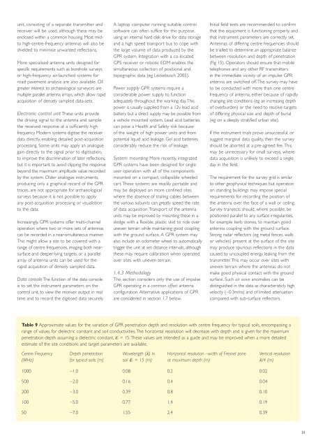
Table 9 Approximate values for the variation of GPR penetration depth and resolution with centre frequency for typical soils, encompass<strong>in</strong>g a<br />
range of values for dielectric constant and soil conductivities. The horizontal resolution will decrease with depth and is given for the maximum<br />
penetration depth assum<strong>in</strong>g a dielectric constant, εr = 15. These values are <strong>in</strong>tended as a guide and may be improved when a more detailed<br />
estimate of the site conditions and target parameters are available.<br />
Centre Frequency Depth penetration Wavelength (λ) <strong>in</strong> Horizontal resolution –width of Fresnel zone Vertical resolution<br />
(MHz) for typical soils (m) soil εr = 15 (m) at maximum depth (m) λ/4 (m)<br />
1000 ~1.0 0.08 0.2 0.02<br />
500 ~2.0 0.16 0.4 0.04<br />
200 ~3.0 0.39 0.8 0.10<br />
100 ~5.0 0.77 1.4 0.19<br />
50 ~7.0 1.55 2.4 0.39<br />
31