VALVE SET - Hjallerup Maskinforretning A/S
VALVE SET - Hjallerup Maskinforretning A/S
VALVE SET - Hjallerup Maskinforretning A/S

Create successful ePaper yourself
Turn your PDF publications into a flip-book with our unique Google optimized e-Paper software.
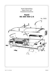
ENGLISH (103 -157)<br />
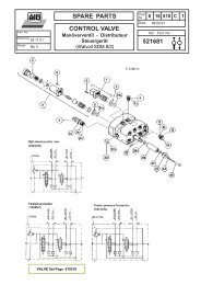
DESCRIPTION<br />
This valve set consists of:<br />
1 Control valve (Loadsensing) with two double acting<br />
functions. The function for the loader lift rams is<br />
equipped with float position.<br />
1 SINGLE-lever control device with a switch for<br />
SELECTO<br />
1 Electr. connector with cables<br />
1 Bracket for the electr. connector<br />
1 Bag containing assembly parts<br />
This valve set shall be mounted with a hydraulic kit,<br />
especially adapted for each tractor model<br />
Check before mounting that the set is aimed for the<br />
tractor / loader in question and that the contents is in<br />
accordance with enclosed mounting instruction.<br />
MOUNTING<br />
In many cases the mounting will be easier if the rear<br />
wheels of the tractor are removed.<br />
Start by mounting the control cables in the control<br />
device.<br />
- Loosen the upper part of the control device (put a<br />
screw-driver into the track acc. to fig.1).<br />
- Loosen the two stop screws and the screw (A) holding<br />
the pivot (B) of the yoke.<br />
- Push the cables into the holes (X) and (Y) of the<br />
control device housing and guide them into the track<br />
of the yoke. Fig. 2.<br />
- Guide the pivot (B) into the yoke and press the cables<br />
backwards, fig. 3. Then screw the pivot into the<br />
control device housing.<br />
- Fig.6<br />
Push collar and housing together and check that the<br />
gaiter (K) tightens.<br />
- Use the stop screws to lock the cables. Make sure<br />
that the screws fit the locking grooves. This<br />
position is obtained when the treated part of the<br />
cable is level with the bottom part of the housing.<br />
Fig.4. Verify that the electr. cables don't get<br />
jammed between yoke and housing.<br />
N.B.!!<br />
It is important that the control device housing is mounted<br />
with the firm pivot (B) placed in the right rear edge,<br />
independent of the control device being installed to the<br />
right or to the left of the driver's seat.<br />
- Install the valve on the right subframe of the loader<br />
acc. to the mounting instruction for the hydraulic<br />
connection. On some subframes of the old type there<br />
is a bracket welded to fit another type of valve - don't<br />
use this one !<br />
- If necessary, drill holes (Ø 13 - 15 mm) through the<br />
cabin floor.<br />
- Install the control device on the place indicated using<br />
the bracket supplied, Make sure, when drilling holes,<br />
that no hidden electric cables get damaged.<br />
Remark !<br />
On loaders equipped with hydraulic implement locking,<br />
the bracket (if any) for the safety switch shall be fitted<br />
together with the control device - see the mounting<br />
instruction for the hydraulic implement locking.<br />
If the control device is installed from the side, the<br />
sleeves (D) must be moved and cut.<br />
- Lock the control device in neutral position with the<br />
safety catch (E).<br />
- Draw the cables up to the valve. Avoid sharp bends<br />
less than 200 mm in radius.<br />
- Slip the washer (G), the locking ring (H) and the<br />
sleeve (F) over the cable. Do NOT place the locking<br />
ring in a groove. N.B.!! turn the tapered side of the<br />
washer towards the valve.<br />
To obtain the correct lever movement, the control<br />
cable from the right front hole (X) of the control<br />
device shall be connected to the lift function of the<br />
valve (slide A - B).<br />
- Fasten the cable in the valve slide using the locking<br />
pin (J).<br />
- Make sure that the control device is locked in neutral<br />
position. Push the sleeve, the locking ring and the<br />
washer backwards. See to it that the adjusting sleeve<br />
fits into the middle part and that the locking ring is<br />
placed in the chamfering of the washer.<br />
103<br />
- Screw on the sleeve.<br />
MOUNTING - the connector for SELECTO<br />
Install the bracket (31) for the connector on the right<br />
subframe or on the plate holding the control valve.<br />
Connect the cable from the electr.control device to the<br />
connector according to the wiring diagram - the leaders<br />
are marked 1,2,3.<br />
Connect the connector to the current source (12V+) and<br />
the earth wire to the tractor body.