VALVE SET - Hjallerup Maskinforretning A/S
VALVE SET - Hjallerup Maskinforretning A/S
VALVE SET - Hjallerup Maskinforretning A/S

Create successful ePaper yourself
Turn your PDF publications into a flip-book with our unique Google optimized e-Paper software.
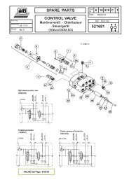
CONTROL<br />
- Disconnect the safety catch (E) and check that the<br />
control device lever always returns to neutral position<br />
except when the lever is brought maximally forwards to<br />
floating position.<br />
The lever should then remain in this position.<br />
Lever movement:<br />
Backwards - Lifting of loader beam<br />
Forwards - Sinking of loader beam + floating function<br />
Left - The implement is crowded upwards 1)<br />
Right - The implement is emptied 1)<br />
1) Tobtain the reverse lever movement (LH fitting), the<br />
hoses marked yellow and red (implement function)<br />
will have to change places. Check that the direction<br />
indicator on the MONO-lever corresponds to the<br />
movements of the loader - the handle will be supplied<br />
with a new top for left hand fitting. The ref no of this<br />
top is 50 20 385. See fig.A.<br />
The loader shall be connected to the valve acc. to the<br />
colour marking:<br />
GREEN (B1) = Sink<br />
BLUE (A1) = Lift<br />
YELLOW (A2) = Tip<br />
RED (B2) = Crowd<br />
YELLOW (A2) = Tip<br />
Connect the valve to the tractor hydraulics acc. to<br />
separate mounting instruction. Therefore only general<br />
information is given here.<br />
ENGLISH (105 -157)<br />
- Connect the tractor pump ( pressure) to the valve port<br />
(P).<br />
- Port T - connect to tank (return).<br />
- Port LS - aimed for signalling circuit.<br />
Test run all the functions of the loader (towards end<br />
positions) and check that there are no oil leakages.<br />
Check after test run that the oil level in the tractor's<br />
hydraulics system is sufficient ( all hydraulic rams<br />
compressed). Fasten the hydraulic hoses with clamps<br />
so that they do not wear against pedals and control<br />
stays, if any.<br />
REMARK !<br />
The valve is equipped with safety valves (M) for the<br />
lifting function (240 bar) of the loader.<br />
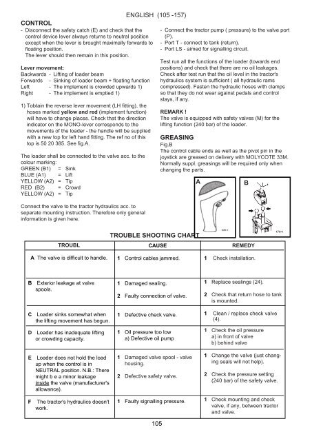
GREASING<br />
Fig.B<br />
The control cable ends as well as the pivot pin in the<br />
joystick are greased on delivery with MOLYCOTE 33M.<br />
Normally suppl. greasings will be required only when<br />
changing the parts.<br />
A<br />
B<br />
TROUBL<br />
A The valve is difficult to handle.<br />
TROUBLE SHOOTING CHART<br />
CAUSE<br />
1 Control cables jammed.<br />
REMEDY<br />
1 Check installation.<br />
B<br />
Exterior leakage at valve<br />
spools.<br />
1 Damaged sealing.<br />
2 Faulty connection of valve.<br />
1 Replace sealings (24).<br />
2 Check that return hose to tank<br />
is mounted.<br />
C<br />
Loader sinks somewhat when<br />
the lifting movement has begun.<br />
1 Defective check valve.<br />
1 Clean / replace check valve<br />
(4).<br />
D<br />
Loader has inadequate lifting<br />
or crowding capacity.<br />
1 Oil pressure too low<br />
a) Defective oil pump<br />
1 Check the oil pressure<br />
a) in front of valve<br />
b) behind valve<br />
E<br />
Loader does not hold the load<br />
up when the control is in<br />
NEUTRAL position. N.B.: There<br />
might b e a minor leakage<br />
inside the valve (manufacturer's<br />
allowance).<br />
1 Damaged valve spool - valve<br />
housing.<br />
2 Defective safety valve.<br />
1 Change the valve (just changing<br />
seals will not help).<br />
2 Check the pressure setting<br />
(240 bar) of the safety valve.<br />
F<br />
The tractor's hydraulics doesn't<br />
work.<br />
1 Faulty signalling pressure.<br />
1 Check mounting and check<br />
valve, if any, between tractor<br />
and valve.<br />
105