January 1998 Thomas Henry - Power Supplies for Electronic Music.pdf
January 1998 Thomas Henry - Power Supplies for Electronic Music.pdf
January 1998 Thomas Henry - Power Supplies for Electronic Music.pdf

Create successful ePaper yourself
Turn your PDF publications into a flip-book with our unique Google optimized e-Paper software.
y <strong>Thomas</strong> <strong>Henry</strong><br />
Agood quality power supply is essential<br />
<strong>for</strong> homemade electronic music equipment.<br />
And yet, do-it-yourselfers often<br />
give short shrift to this important module.<br />
The general attitude seems to be<br />
that the power supply is an annoyance;<br />
you’ve got to have one, but since it doesn’t make any<br />
neat sounds, it frequently fails to get the attention it<br />
deserves.<br />
This article addresses the problem by explaining<br />
why, in fact, power supplies are crucial to good per<strong>for</strong>mance<br />
from electronic music equipment. It then<br />
goes on to show you how to construct your own.<br />
Actually, kit companies haven’t helped the situation<br />
much. Many of the power supply kits currently<br />
available are lacking in one regard or another. For<br />
example, at the time of this writing, one company<br />
offers a bipolar power supply which isn’t even regulated,<br />
while another lists a regulated one, but the<br />
available current is minuscule. Build your own<br />
power supply and you can easily overcome these<br />
hurdles!<br />
<strong>Power</strong> <strong>Supplies</strong> <strong>for</strong><br />
<strong>Electronic</strong> <strong>Music</strong><br />
DESIRABLE FEATURES<br />
<strong>Power</strong> supplies <strong>for</strong> electronic music should be<br />
regulated and there are several good reasons why.<br />
First, hum caused by supply ripple is nipped in the<br />
bud. Since the regulator clamps the filtered DC to a<br />
fixed level, any residual bumps are neatly truncated.<br />
Next, the output voltage will remain relatively<br />
stable, even if you start adding more modules to<br />
your system. (Most homemade music equipment is<br />
modular in nature, with all of the individual circuits<br />
being powered by a main supply.)<br />
Another advantage to regulation relates specifically<br />
to voltage-controlled oscillators (VCOs) used in<br />
music synthesizers. By powering the VCO from a regulated<br />
supply, you can be sure that the tuning won’t<br />
drift all over the place. This will keep your listeners<br />
from having to suffer through “clinkers” or sour<br />
notes!<br />
Finally, regulated supplies typically have a great<br />
deal of safety protection built into them. With a modern<br />
design, it is possible to guard against input or output<br />
short circuits, as well as overheating.<br />
With regard to current, a decent power supply<br />
should be able to provide at least a half amp or so on<br />
each output. As hinted at above, a modular system<br />
may consist of a dozen or more separate circuits, each<br />
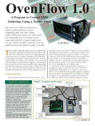
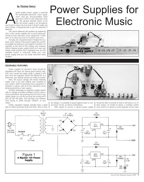
Figure 1<br />
A Bipolar 15V <strong>Power</strong><br />
Supply.<br />
Nuts & Volts Magazine/<strong>January</strong> <strong>1998</strong> 7
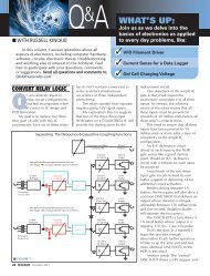
Figure 2<br />
A +5V <strong>Power</strong><br />
Supply.<br />
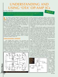
Figure 3<br />
Modification <strong>for</strong> a<br />
Combined <strong>Power</strong><br />
Supply.<br />
one drawing current from the supply. The idea here,<br />
then, is to build a power supply once making sure that<br />
it has enough beef to handle a number of modules.<br />
What voltages are needed <strong>for</strong> electronic music<br />
devices? Well, <strong>for</strong> analog circuitry, history has shown<br />
that a bipolar 15V supply is best <strong>for</strong> a variety of reasons.<br />
Perhaps the most important is that many of the<br />
classic special-purpose synthesizer chips require this. It<br />
is not uncommon to encounter music ICs which operate<br />
only on a bipolar 15V, or perhaps just a single +15V<br />
line. But even <strong>for</strong> discrete or homebrew op-amp<br />
designs, these voltages are a good choice.<br />
Here’s why. By using a bipolar 15V instead of, say,<br />
a bipolar 9V supply, you attain much greater headroom<br />
throughout the circuit be<strong>for</strong>e clipping occurs. In audio<br />
circuitry, as a general rule, the greater the headroom,<br />
the better the distortion and noise figures will be.<br />
It’s no secret that modern music is being invaded by<br />
microprocessors. Hence, it would be wise to also have a<br />
source of +5V available. This is a pretty standard voltage<br />
<strong>for</strong> most microprocessors, as well as TTL circuits.<br />
We can put these factors all together to come up<br />
with a design plan. We will shoot <strong>for</strong> a regulated<br />
power supply, capable of providing +15V, -15V, and<br />
+5V, with 0.75 amps available from each line.<br />
Moreover, we will demand excellent safety requirements<br />
like short circuit and overheating protection.<br />
These goals are easily met with just a tad of care. So,<br />
let’s see what it takes.<br />
DESIGN ANALYSIS<br />
Refer to Figure 1 which shows the schematic of a<br />
bipolar 15V power supply. A standard 110V AC enters<br />
the circuit from the left, via wall plug P1 and an 18-<br />
gauge line cord. This passes through the main power<br />
switch, S1. More importantly, it also goes to fuse F1.<br />
A fuse is essential not just <strong>for</strong> your safety, but also<br />
<strong>for</strong> the well-being of any other gear connected. By the<br />
way, this is a 1A fast blow fuse, but we’ll wait just a bit<br />
be<strong>for</strong>e seeing how that value was arrived at.<br />
T1 is a 36V center-tapped trans<strong>for</strong>mer rated at<br />
1.5A. Theoretically, since we’ll be using a bridge rectifier<br />
arrangement across the entire secondary, we<br />
should be able to draw 1.5A from both the +15V and<br />
-15V sides.<br />
However, we’ll introduce a good safety margin<br />
here by specifying the supply as 0.75A per side. This<br />
puts less stress on the trans<strong>for</strong>mer, permitting it to run<br />
cooler and you to breathe easier.<br />
The bridge rectifier composed of D1 through D4<br />
creates pulsating DC voltages of both positive and negative<br />
polarities. These two voltages will be referenced<br />
to the ground established by the center tap of T1’s secondary.<br />
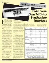
Figure 4<br />
1:1 Foil Side Artwork<br />
8 <strong>January</strong> <strong>1998</strong>/Nuts & Volts Magazine
Figure 5<br />
Parts Placement<br />
Guide.<br />
Notice that the bridge implements<br />
fullwave rectification. This is<br />
an extremely efficient approach,<br />
since both the positive and negative<br />
portions of the AC input are<br />
used. Also, the pulsating DC will<br />
have a frequency of 120 Hz now<br />
(twice the 60 Hz input) which is<br />
easier to filter.<br />
By the way, all of the rectifiers<br />
in this circuit should be rated <strong>for</strong> a<br />
peak inverse voltage of at least<br />
100V and a current capability of<br />
1A. The 1N4002 is a good choice<br />
here. The positive output is found<br />
at the junction of D1 and D3. This<br />
is applied to filter capacitor C3.<br />
Most text books have standard<br />
<strong>for</strong>mulas <strong>for</strong> determining the<br />
optimal value of power supply filter<br />
capacitors; it turns out that 1000<br />
mfd works well here. But watch<br />
the voltage rating! The capacitor will store the peak<br />
value of the pulsating DC which, in the worst case, will<br />
be about 25V. Thus, <strong>for</strong> a good margin of safety,<br />
choose C3 to have a working voltage of double that.<br />
(Curious about that 25V? Well, trans<strong>for</strong>mers are rated<br />
in volts RMS; multiply this by 1.414 to determine the<br />
peak voltage. Doing so shows you that T1 will generate<br />
a peak voltage of about 50V. Divide that by two to<br />
get the value <strong>for</strong> each half of the secondary.)<br />
The next step is to regulate the voltage on C3 and<br />
that’s the purpose of IC1, the well-known 7815. The<br />
input voltage to this chip should be higher than the<br />
desired output voltage. If the input is too low, say 18V<br />
or below, then you’ll drop out of regulation. And if it’s<br />
too high, then the regulator will run hot. (Essentially,<br />
may be (as long as it’s reasonably close to +15V).<br />
The input and output pins of IC1 should be stabilized,<br />
especially if there’s any messy wiring leading up<br />
to them. So, it’s generally a wise idea to attach bypass<br />
capacitors very close to the pins.<br />
Since we’ll probably be building this on a printed<br />
circuit board (which is inherently tidy), and will locate<br />
C3 close to IC1, there’s really no need <strong>for</strong> a cap on the<br />
input. However, the output could be feeding a variety<br />
of other modules through a tangle of wires. So we’ll<br />
tack on capacitor C1 to the output pin. This will<br />
improve the transient response of the chip.<br />
The 7815 regulator is pretty neat in that it has<br />
some internal protection circuitry. If the IC overheats<br />
<strong>for</strong> any reason, it simply shuts itself down until the con-<br />
slipped with a pair of pliers. In<br />
that brief instant of time, the<br />
output voltage of IC1 will be<br />
higher than the input which is<br />
now at 0V due to the short<br />
across C3. And that’s all it<br />
takes to fry the chip!<br />
However, notice rectifier<br />
D5. Normally, this will be<br />
reverse-biased and just sits<br />
there doing nothing. But, if<br />
that slip of the pliers really<br />
happens, then the cathode<br />
drops to 0V. The rectifier goes<br />
into <strong>for</strong>ward bias and clamps<br />
Figure 6<br />
A multiple is<br />
nothing more<br />
than several jacks<br />
wired in parallel.<br />
Acting like a “Ycord,”<br />
it’s a utility<br />
device that lets<br />
you split a single<br />
patch cord into<br />
several outputs.<br />
There is room <strong>for</strong><br />
two of these (four<br />
jacks each) on the<br />
1U rack panel<br />
fronting the<br />
power supply.<br />
Figure 7 - The switch, LED, and fuse <strong>for</strong> the power supply fit behind a standard 1U rack panel, leaving plenty of room <strong>for</strong> two multiples.<br />
the 7815 “throws away” any excess energy in the<br />
<strong>for</strong>m of heat.) Of course, the voltage on C3 fluctuates<br />
as the output load changes, but typically will lie<br />
between 20V and 25V. Even though the input is moving<br />
about, the output will hold rock solid thanks to the<br />
7815.<br />
By the way, don’t be surprised if the output of IC1<br />
doesn’t hit +15V on the button. According to the manufacturer’s<br />
spec sheet, the output <strong>for</strong> a given 7815<br />
may lie anywhere between +14.4V and +15.6V. This<br />
doesn’t matter, in general. What’s important is that<br />
the output be locked into some voltage whatever it<br />
Figure 8<br />
Drilling Guide <strong>for</strong> the 1U Rack Panel.<br />
All dimensions in inches.<br />
dition is corrected. Notice that this covers output short<br />
circuits as well.<br />
And speaking of heat, it is essential that IC1 (and<br />
the other two voltage regulators mentioned in this article)<br />
be properly heatsinked. That extra surface area<br />
really helps to keep things cool!<br />
But there are two other ways we can easily augment<br />
the protection. For starters, imagine that filter<br />
cap C3 is accidentally shorted to ground. Maybe a<br />
washer rattled loose inside the cabinet, or perhaps you<br />
the output to more or less the same level as the<br />
input. To put it another way, it is now impossible<br />
<strong>for</strong> the input of IC1 to ever drop substantially lower<br />
than the output.<br />
D6 per<strong>for</strong>ms another useful task. Its purpose is to<br />
ensure that the output line feeding all of the other<br />
modules can never go negative. Of course, this would<br />
normally be impossible. But imagine that some other<br />
module in your system goes haywire or that you accidentally<br />
cross the supply lines in some fashion. D6<br />
snaps to attention and safely dumps the negative voltage<br />
to ground.<br />
Nuts & Volts Magazine/<strong>January</strong> <strong>1998</strong> 9
Pause <strong>for</strong> a moment to really consider what we<br />
have accomplished so far. We now have a decent regulated<br />
+15V at our disposal, and it can handle a whopping<br />
0.75A. Overheating and output short circuits are<br />
no longer part of our nightmares. And best of all,<br />
we’ve protected the supply itself, as well as any other<br />
potentially expensive equipment in our system.<br />
With just a little extra care, we have truly come up<br />
with a platinum power supply!<br />
Generating a -15V is just as easy, if you keep a few<br />
simple component orientations in mind. Refer again to<br />
Figure 1. The junction of D2 and D4 spits out a negative<br />
pulsating DC voltage. This is filtered by C4 and<br />
then tamed by IC2, the 7915 negative voltage regulator.<br />
C2 then stabilizes the output of the regulator.<br />
However, observe carefully the polarities of both C2<br />
and C4; they’re the reverse of what appeared in the<br />
description <strong>for</strong> the positive supply. D7 and D8 provide<br />
goof-proofing, but again notice how the orientation is<br />
flipped here. An easily missed point is that the 7815<br />
and 7915 regulators have different pinouts. Keep this<br />
in mind, unless you enjoy fireworks!<br />
A panel LED is always nice to give visual indication<br />
that the circuit is on. This is the purpose of D9 and its<br />
current limiting resistor R1. Incidentally, in most electronic<br />
music equipment, the positive supply gets more<br />
of a workout than the negative. So, we put the LED on<br />
the -15V side just to even things out a trifle.<br />
BIPOLAR 15V POWER SUPPLY<br />
Resistor<br />
R1 1.5K, 1/4W<br />
Capacitors<br />
C1, C2 10 mfd, 25V electrolytic<br />
C3, C4 1000 mfd, 50V electrolytic<br />
Semiconductors<br />
D1 - D8 1N4002 rectifier<br />
D9 Red LED<br />
IC1 7815 voltage regulator<br />
IC2 7915 voltage regulator<br />
Other Components<br />
T1 36VCT, 1.5A trans<strong>for</strong>mer<br />
S1 SPST heavy duty toggle switch<br />
F1 A fast blow fuse<br />
P1 18 gauge line cord with plug<br />
Miscellaneous<br />
Printed circuit board, heatsinks, panel mount fuse<br />
holder, heat shrink tubing, LED clip, #4 hardware<br />
(nuts, bolts, lock washers), wire, heatsink grease,<br />
solder, etc.<br />
+5V POWER SUPPLY<br />
Resistor<br />
R1 470 ohms, 1/4W<br />
Capacitors<br />
C1 10mfd, 25V electrolytic<br />
C2 2200mfd, 25V electrolytic<br />
Semiconductors<br />
D1 - D6 1N4002 rectifier<br />
D7 red LED<br />
IC1 7805 voltage regulator<br />
Other Components<br />
T1 9V, 1A trans<strong>for</strong>mer<br />
S1 SPST heavy duty toggle switch<br />
F1 1/2A fast blow fuse<br />
P1 18 gauge line cord with plug<br />
Miscellaneous<br />
Printed circuit board, heatsink, panel mount fuse<br />
holder, heat shrink tubing, LED clip, #4 hardware<br />
(nuts, bolts, lock washers), wire, heatsink grease,<br />
solder, etc.<br />
10 <strong>January</strong> <strong>1998</strong>/Nuts & Volts Magazine<br />
Now about that fuse, F1. Its value depends on the<br />
total power dissipated by the circuit. Recall that some<br />
of this power will be in the output of the supply, but<br />
some will also be in the heat generated by the regulators.<br />
And then we have to allow <strong>for</strong> losses in the trans<strong>for</strong>mer,<br />
as well as the rectifiers.<br />
We don’t have to be slavish about this, so a quick<br />
estimation shows that the bipolar power supply might<br />
draw as much as 60 watts. This suggests a total current<br />
drain of 0.5A (60W divided by 120V).<br />
To avoid blowing fuses repeatedly, and yet provide<br />
good protection from serious conditions, we’ll double<br />
this to arrive at a final suggested rating of 1A.<br />
As mentioned earlier, if you plan on using any<br />
microprocessor or TTL circuitry in your rig, then you will<br />
definitely want to have a source of +5V. We can use<br />
many of the same techniques to carry out this plan.<br />
Refer to Figure 2 now.<br />
The line voltage is applied to T1 by way of switch<br />
S1 and fuse F1. In this case, F1 is a 1/2A fast blow<br />
type. sT1 is a 9V trans<strong>for</strong>mer, rated at 1A. As usual,<br />
we’ll derate things a bit just to permit a decent safety<br />
factor. So, instead of turning this circuit into a toaster<br />
oven, we’ll specify the maximum output current at<br />
0.75A. For best efficiency, a bridge rectifier arrangement<br />
is used again. But since we’re only creating a single<br />
supply voltage (+5V), the trans<strong>for</strong>mer doesn’t need<br />
a center tap on the secondary. Instead, the junction of<br />
PARTS LIST<br />
ORDERING INFORMATION<br />
The following kits are available from Midwest<br />
Analog Products:<br />
+5V <strong>Power</strong> Supply — Kit of parts includes an<br />
Assembly Guide and all items mentioned in the<br />
Parts List except heatsink grease and solder. Part<br />
Number PPS-1, $24.95 (plus $3.00 shipping and<br />
handling).<br />
Bipolar 15V <strong>Power</strong> Supply — Kit of parts includes an<br />
Assembly Guide and all items mentioned in the<br />
Parts List except heatsink grease and solder. Part<br />
Number PP2-1, $39.95 (plus $4.00 shipping and<br />
handling).<br />
Combo <strong>Power</strong> Supply — Includes both kits (+5V and<br />
Bipolar 15V) as described above. Part Number PPS-<br />
3, $59.95 (plus $6.00 shipping and handling).<br />
Blank Rack Panel Kit — includes an unfinished 1-<br />
3/4” by 19” by 1/8” aluminum panel, angles, and<br />
hardware <strong>for</strong> mounting a circuit board, and instructions<br />
on how to drill, cut, and work with rack panels.<br />
Part Number K901, $8.95 (plus $3.00 shipping<br />
and handling).<br />
Shipping is by First Class Mail. Prices shown in US<br />
dollars. Remit US funds only. Write <strong>for</strong> shipping<br />
in<strong>for</strong>mation to other countries. MN residents add<br />
6.5% sales tax. Money orders and checks only.<br />
Prices and terms subject to change without notice.<br />
Order from:<br />
Midwest Analog Products<br />
P.O. Box 2101<br />
North Mankato, MN 56003<br />
E-Mail: map@prairie.lakes.com<br />
WWW: http://prairie.lakes.com/~map<br />
D2 and D4 creates the ground reference.<br />
The positive pulsating DC voltage at the tie point<br />
of D1 and D3 feeds into filter capacitor C2. The voltage<br />
on C2 will vary from about +10V to +13V, depending<br />
on the load conditions. A few standard calculations<br />
come up with a value of 2200 mfd at 25V <strong>for</strong> this<br />
capacitor (once more allowing <strong>for</strong> a margin of safety).<br />
If a clean printed circuit board pattern is used, and<br />
C2 is kept close to the regulator, then no bypass capacitor<br />
should be needed on the input pin of IC1. But we<br />
definitely want to stabilize the output a bit, and that is<br />
the purpose of C1.<br />
And always mindful of things that can go wrong,<br />
we plop in D5 and D6 to guard against nasty voltage<br />
reversals and short circuits. Finally, panel LED D7 provides<br />
visual indication that the unit has been energized.It<br />
is highly likely that you will want both a +5V<br />
and a bipolar 15V power supply in your electronic<br />
music rig.<br />
In this case, refer to Figure 3 which shows how to<br />
combine them. Essentially, you simply parallel the primaries<br />
of the two trans<strong>for</strong>mers, eliminating the redundant<br />
switch, fuse, and line cord. Notice, though, that<br />
the fuse should now be rated at 1.5A to cover both<br />
supplies. Finally, you can ax one of the LEDs, if desired.<br />
BUILDING YOUR OWN POWER SUPPLY<br />
CAUTION: <strong>Power</strong> supplies, like this circuit, use<br />
110V AC which can be dangerous and even lethal!<br />
Do not attempt this project unless you are skilled<br />
at working with 110V AC.<br />
Let’s assume that you want to build both power<br />
supplies mentioned above and house them as a single<br />
unit. To simplify things, we’ll juxtapose the two circuit<br />
boards in the illustrations. Refer to Figure 4 which<br />
shows the foil side artwork <strong>for</strong> the joint project.<br />
Obviously, if you only need one or the other, simply<br />
delete the unwanted portion. If you enjoy etching<br />
printed circuit boards, then have at it!<br />
On the other hand, if you would just as soon avoid<br />
messing about with chemicals and wish to simplify the<br />
task of locating all of the components, then check the<br />
Parts List <strong>for</strong> kit availability via mail order.<br />
There are three interesting things to notice about<br />
the printed circuit board. First, observe how fat the<br />
traces are; this not only permits greater current flow,<br />
but also helps draw heat away from the rectifiers.<br />
Next, three large pads stand out from the rest.<br />
These are drilled to a 1/8” diameter, which then permits<br />
you to secure the heatsinks to the board with #4<br />
machine bolts and nuts. Lastly, the various outputs feature<br />
a large number of paralleled pads <strong>for</strong> powering a<br />
multitude of modules.<br />
Now, you’ll have to take care of running down all<br />
of the parts. Most of these are easy to find, but the<br />
36VCT trans<strong>for</strong>mer rated at 1.5A might take some digging<br />
in the catalogs. Even though this is a standard<br />
size, it isn’t nearly as common as the “filament” types.<br />
And when you do find it, don’t be surprised at the<br />
cost! These are always fairly expensive, but keep in<br />
mind that you’ll only need one to handle quite a few<br />
modules in your system.<br />
When you’re shopping, don’t <strong>for</strong>get the niceties<br />
like heat shrink tubing, tie bands, panel mount fuse<br />
holder, hefty power switch, line cord, etc. In particular,<br />
you’ll want to be especially mindful of how you’re<br />
going to handle the 110V AC side of things.<br />
Remember the cardinal rule: All joints carrying<br />
110V AC must be completely covered and insulated!<br />
If you’re ready to build, then refer to Figure 5<br />
which shows the parts placement guide <strong>for</strong> the printed<br />
circuit board. This is pretty straight<strong>for</strong>ward. But here<br />
are a few tips to help you along.<br />
When loading the board, take great pains to see<br />
that you orient the capacitors and rectifiers properly.<br />
And don’t <strong>for</strong>get that there is one jumper on the
oard. This is denoted by the letter “J.” You can use a<br />
leftover snippet of a rectifier lead to <strong>for</strong>m the jumper.<br />
Be<strong>for</strong>e soldering any one of the three regulators in<br />
place, smear a thin layer of heatsink grease across the<br />
underside. (Small, inexpensive tubes of heatsink grease<br />
are readily available at your local Radio Shack.) Then<br />
bolt the regulator to its heatsink. It probably ought to<br />
be said <strong>for</strong> emphasis: In order to draw the requisite<br />
0.75A from each line of the power supply, heatsinks<br />
and heatsink grease are mandatory.<br />
With regard to how the trans<strong>for</strong>mer secondaries<br />
attach to the board, consider the bipolar supply first.<br />
Two of the pads are marked “SEC;” these connect to<br />
the outer legs of the secondary winding. The third pad<br />
denoted “CT” attaches to the secondary’s center<br />
tap.The +5V supply is simpler; just connect up the two<br />
secondary lines (in either order) to the pads marked<br />
“SEC.”<br />
Finally, the anodes and cathodes of LEDs D7 and<br />
D9 are called out on the parts placement guide by the<br />
letters “a” and “c,” respectively.<br />
Apart from making sure that you’ve left ample<br />
room <strong>for</strong> air flow and that none of the 110V AC connections<br />
can come in contact with the remaining circuitry,<br />
it really doesn’t matter how you mount or<br />
enclose the power supply. Most musicians prefer to use<br />
rack-mounted equipment. In this case, you would install<br />
the power supply at the bottom of your cabinet, so that<br />
the heavy trans<strong>for</strong>mers can be bolted to its floor.<br />
Now power supplies don’t require much in the<br />
way of front panel real estate; room <strong>for</strong> a switch, a<br />
fuse holder, and an LED is about all it takes.<br />
It’s a shame to waste any of the remaining surface<br />
area, so you might want to consider adding in some<br />
simple utility options. One of the most useful is a “multiple.”<br />
This is nothing more than a bunch of jacks that<br />
have been wired in parallel, sort of like a rack-mounted<br />
“Y-cord.” See Figure 6. Multiples are extremely handy<br />
in the studio, since they allow you to drive several different<br />
devices from a single source.<br />
If this approach appeals to you, then refer to<br />
Figure 7 which illustrates one possible layout.<br />
Everything fits readily behind a standard 1U panel (1-<br />
3/4” by 19”).<br />
Figure 8 shows the associated drilling guide. The<br />
printed circuit board mounts behind the completed<br />
panel on little angles, secured in place by some #4<br />
bolts, lock washers, and nuts.<br />
CHECKING THINGS OUT<br />
And that’s it! There are no adjustments to be<br />
made be<strong>for</strong>e using your new power supply. But do<br />
take a few extra moments to inspect your handiwork<br />
once more be<strong>for</strong>e you first plug it in.<br />
If everything looks hunky-dory, take the plunge<br />
and fire up the circuit. Assuming you successfully pass<br />
the smoke test, get out your multimeter and verify that<br />
you have voltages reasonably close to +15V,<br />
-15V, and +5V available.<br />
While this may have seemed a bit of detour from<br />
your usual activity of creating cool sounds, it will have<br />
all been worth it. For you now have the confidence<br />
that your valuable music gear is being powered by a<br />
stable and steadfast unit. And, with a full 0.75A available<br />
on each of the three lines, you shouldn’t have to<br />
build another power supply <strong>for</strong> quite some time. So,<br />
start hooking up your sound modules and get back to<br />
doing what you like best: making music! NV<br />
AD HERE<br />
Nuts & Volts Magazine/<strong>January</strong> <strong>1998</strong> 11