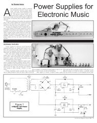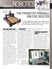
download - Nuts & Volts Magazine
download - Nuts & Volts Magazine
download - Nuts & Volts Magazine
- No tags were found...

Create successful ePaper yourself
Turn your PDF publications into a flip-book with our unique Google optimized e-Paper software.
Web Site: www.parallax.comForums: forums.parallax.comSales: sales@parallax.comTechnical: support@parallax.comOffice: (916) 624-8333Fax: (916) 624-8003Sales: (888) 512-1024Tech Support: (888) 997-8267Stingray Robot (#28980)The Stingray robot from Parallax Inc. provides a mid-size platform for a wide range of robotics projects andexperiments. The Propeller Robot Control Board is the brains of the system providing a multiprocessorcontrol system capable of performing multiple tasks at the same time. The Propeller chip provides eight 32-bit processors each with two counters, its own 2 KB local memory and 32 KB shared memory. This makesthe Propeller a perfect choice for advanced robotics and the Stingray robot.Features• Multicore Propeller chip based control board• Extra large EEPROM (64 KB) for storing additionaldata• On-board 3.3 V & 5V switching power supply• 5 V I/O translators to simplify interfacing to 5 Vsensors/devices• Integrated dual full bridge driver• Two DC spur gear motors• Two-wheel differential drive system with rear omnidirectionalwheel• Multiple mounting locations for sensors, add-ons,etc.• Free online Propeller Tool programming software forWindows and example Stingray source code(requires Win2K/XP/Vista, IE7 or higher, and USB port)Key Specifications• Power requirements: 6 AA 1.2 V Rechargeable Batteries (not included)• Communication: USB A to Mini B Cable (included)• Operating temperature: 32 to 158 °F (0 to 70 °C)• Dimensions, assembled: 13” L x 10.9” W x 5.5” H (33 x 27.7 x 14 cm)PrerequisitesThis document covers assembly of your Stingray robot and testing of its motors. The Stingray is intended forthose with previous programming and electronics experience, specifically prior experience with the Propellerchip microcontroller. The following resources are recommended for Propeller beginners:• Propeller Education Kit Labs: This educational text is a great way to get started with the Propeller.It focuses on general Propeller programming and interfacing. The complete PDF and source code areincluded in the Propeller Tool v1.2.6 or later Help file.• The Propeller Manual and Propeller Datasheet: These invaluable reference materials are alsoincluded in the Propeller Tool v1.2.6 or later Help file.• The Propeller chip Forum (www.forums.parallax.com) At the top of the Propeller forum there is asticky thread titled “Propeller: Getting Started and Key Thread Index.” This link contains a wealth ofinformation from Parallax and other sources for getting started with the Propeller.Copyright © Parallax Inc. Stingray Robot (#28980) v1.1 10/6/2009 Page 1 of 26
Bill of MaterialsThis table contains a complete list of the parts used in this kit at the time this document was created. Partsand quantities are subject to change without notice. If you have any questions about your kit contents,please contact Parallax through the Tech Support Resources listed on page 26.Part # Description Quantity28230 Propeller Robot Control Board 127950 Motor, 7.2VDC, 310 RPM, 6mm Shaft 2130-32000 PE Kit Project Parts 1452-00060 Battery Retention Clip, 6 AA 1500-00001 Transistor, NPN, Switching, 200 mA 4700-00028 Screw, Zinc, Pan Head, Phillips, #4-40, ¼” 16700-00064 Parallax Screwdriver 1700-00077 Breadboard, 3.19” L x 1.65” W 1700-00081 Breadboard, 30 Row X 2 Column 2710-00017 Screw, Black, Button Socket Cap, #4-40, ¼” 34710-00018 Screw, Black, Button Socket Cap, M3, 6mm 6710-00019 Screw, Black, Phillips Flat Head, #4-40, ¼” 2710-00020 Screw, Zinc, Pan Head, Phillips, #8-32, 3/8” 4712-00004 Washer, Zinc, #6 ID, 3/8” OD 2713-00001 Standoff, Aluminum, ¼” W, Round, 5/8” L, #4-40 8713-00017 Nut, Black Oxide, #4-40 2721-00008 Wheel, 4-7/8” Diameter, Blue Tread 2721-00009 Wheel Hub, Aluminum, 6 mm Shaft (includes o-ring and set screw) 2725-00062 Hex Key, 1/16” 1725-00068 Hex Key, 2 mm 1730-00050 Stingray Chassis Plate 2730-00051 Stingray Motor Mount Plate 2730-00052 Stingray Sensor Mount Plate 5730-00053 Stingray Tail Wheel Mount Plate 1730-00054 Multi-Directional Tail Wheel (Omni-Wheel) 1730-00055 Stingray Tail Wheel Axle 1730-00056 Handle, Aluminum, 3” Length, #8-32 Screw 2730-00057 Breadboard Mounting Plate 1753-00003 Battery Holder, 6AA, 12” w/Connector 1800-00037 Jumper Wire, F-M, 120mm, 10-Pack 1800-28900 Wire, 2-Conductor (Green/White), 20AWG, 10” 1800-28980 Wire, 2-Conductor (Blue/White), 20AWG, 10” 1805-00006 USB A to Mini B Cable 1Assembly InstructionsThis section will guide you step-by-step as you assemble your Stingray robot. Each step will describe theparts and tools required and then the procedure to assemble them. Each step contains a CAD drawing as avisual aid to the instructions. Be sure to follow each step carefully.Copyright © Parallax Inc. Stingray Robot (#28980) v1.1 10/6/2009 Page 2 of 26
PreparationMatch the Bill of Materials against the parts in your kit to make sure all parts are present.Find a clean workspace on which to assemble your robot. You might want to put down somenewspaper or cardboard so that the edges of the metal parts do not scratch the work surface.Organize tools and parts prior to starting the assembly and separate parts by type to make it easierto gather them during the assembly process.Throughout the assembly process, when tightening screws be sure to get them nice and snug but donot over-tighten them or you may strip the threads.Additional Tools RequiredTwo hex keys and one Phillips/flathead screwdriver are provided. The following additional tools are required:• Safety glasses• Small pair of needle-nosed pliers• O-ring pliers if you have them (these areoptional, but make things easier)Safety first! Taking basic safety precautions is absolutely necessary when building the Stingray. Theassembly process includes steps where there is the potential for injury. For example, you will be installingan o-ring which could fly off at high velocity if not installed properly. These dangers are minimized bywearing safety glasses during assembly and using the right tools for the job.Stingray Robot Assembly (exploded view of major parts)Note: The metal parts shown in the CAD drawings have been lightened to show detail.Assembled Breadboards onBreadboard Mounting PlatePropeller Robot Control BoardStandoff, AluminumHandle, AluminumStingray ChassisTop PlateMulti-directional Tail WheelO-ringStingray MotorMountPlateBattery Holder andRetention ClipTail WheelMount PlateStingray TailWheel AxleMotorWheel, Blue TreadWheel HubStingray SensorMount PlatesMotor WireAssembliesCopyright © Parallax Inc. Stingray Robot (#28980) v1.1 10/6/2009 Page 3 of 26
STEP 1: Chassis Assembly (lower)Parts Required• (1) Stingray Chassis Plate• (5) Stingray Sensor Mount Plate• (2) Stingray Motor Mount Plate• (1) Stingray Tail Wheel Mount Plate• (16) Screw, Black, Button Socket Cap,#4-40, ¼”Tools Required1/16” Hex Key (included)Use the 1/16” Hex Key and the black #4-40 black button socket cap screws in this step. (Note thatthere are also 6 button socket cap screws and a 2 mm Hex Key; be careful to use the correct type.)Attach the Tail Wheel Mount Plate and Sensor Mount Plates to the Chassis Plate in the orientationshown below.Attach the Motor Mount Plates, being very careful to orient them correctly so that one screw hole isclose to the Chassis Plate, which will be the bottom of the robot.Tip: An easy way to do this step is to attach the Tail Wheel Mount Plate first, then attach the front SensorMount Plate. Now if you turn the Chassis Plate upside down each mount plate will slide right into positionand should be easier to attach.Stingray Sensor Mount PlatesMotor MountPlateMotor MountPlateStingray SensorMount PlateOrient MotorMount Plates soone screw hole isclose to the lowerChassis PlateStingray Tail WheelMount PlateStingray ChassisPlateScrew, Black, Button Socket Cap, #4-40, 1/4”Copyright © Parallax Inc. Stingray Robot (#28980) v1.1 10/6/2009 Page 4 of 26
STEP 2: Motor InstallationParts Required• (2) Motor, 7.2 VDC, 310RPM, 6 mm Shaft• (6) Screw, Black, Button Socket Cap, M3, 6 mmTools Required• 2mm Hex Key (included)Using the included 2 mm Hex Key attach the motors to the Motor Mount Plates using 3 each of theM3 screws as shown in the figure below. The main body of the motors should be toward the bottomof the robot while the shaft should be toward the top.Be sure all three screws in each motor are very snug, but do not over-tighten.Please note that the six M3 screws look very similar to the ones used on the chassis assembly in theprevious step. To distinguish them from the others you can see that the hex hole in the head of the M3 islarger and uses the 2 mm (larger) Hex Key.MotorsMotor MountPlateFront End ofStingray RobotRight Side of Stingray RobotLeft Side ofStingray RobotMotor Mount PlateAssembled Lower ChassisTail End ofStingray RobotScrew, Black, Button SocketCap, #4-40, 1/4”Copyright © Parallax Inc. Stingray Robot (#28980) v1.1 10/6/2009 Page 5 of 26
STEP 3: Motor Wire ConnectionParts Required• (1) Wire, 2-Conductor (Green/White), 20AWG, 10”• (1) Wire, 2-Conductor (Blue/White), 20AWG, 10”Tools Required• NoneThere are two Motor Wire Assemblies. One has a Green/White wire pair while the other has a Blue/Whitewire pair.Connect the Green/White Motor Wire Assembly to the left motor (shown) so that the green wireconnects to the positive terminal and the white wire connects to the other terminal. See the figurebelow for details.Repeat the procedure for the right motor making sure to connect the blue wire to the positiveterminal and the white wire to the other terminal.Left MotorLeft MotorPositive TerminalConnect to green wireLeft MotorOther TerminalConnect to white wireGreen/White Motor Wire AssemblyCopyright © Parallax Inc. Stingray Robot (#28980) v1.1 10/6/2009 Page 6 of 26
STEP 4: Hub InstallationParts Required• (1) Wheel Hub, Aluminum, 6mm Shaft• (4) Hub Set Screws (included with hubs)Tools Required• 1/16” Hex Key (included)Using the included 1/16” Hex Key, install 2 set screws loosely into each Wheel Hub as shown in thefigure below.Slide the hub onto the motor shaft so that the screws line up with the flat part of the motor shaft.The hub should slide all the way onto the shaft with just a small gap (< 1/16”) between the hub andthe motor casing protruding through the motor mount plate.Both set screws should land on the flat part of the motor shaft when tightened down.Gently tighten the set screws. Be careful not to over-tighten the set screw but make sure it is verysnug or the hub may work loose over time.Repeat this procedure for the other motor.Hub Set ScrewsWheel Hub Set Screw holes go overflat part of motor shaftMotorShaftWheel HubMotorCopyright © Parallax Inc. Stingray Robot (#28980) v1.1 10/6/2009 Page 7 of 26
STEP 5: Front Wheel InstallationParts Required• (2) Wheel, 4-7/8” Diameter, Blue Tread• (2) Hub o-ring (included with hubs)Tools Required:• Small pair of needle nosed pliers or snapringpliers (not included)• Safety Glasses (not included)Be sure to wear your safety glasses during this step.Stand the robot on its side so that the hub and wheel are facing upward as shown in the first figurebelow. This will make it easier to install the o-ring onto the hub.Slide one of the wheels onto a hub. You can either hold the robot chassis between your legs orhave someone else hold it in place for this step.To install the o-ring, place it over the hub and hold the back part of the ring in place as shown in theupper right figure.Using the o-ring pliers or small needle nosed pliers, separate the front of the o-ring while pressingdown lightly. This should cause it to snap into place into the groove on the hub as shown in thelower right figure.Repeat with other wheel.Note: A video clip demonstrating how to do install the Hub o-ring with needle nosed pliers is available for<strong>download</strong> on the Stingray product page on our website.Wheel, Blue TreadO-ringPlace o-ring over the hub and hold the back part of thering in place.With pliers, separate the front of the o-ring whilepressing down lightly.Wheel Hub mounted on MotorShaft with Set ScrewsWhen the O-ring snaps into place into the groove onthe hub, release the pliers.Copyright © Parallax Inc. Stingray Robot (#28980) v1.1 10/6/2009 Page 8 of 26
STEP 6: Tail Wheel InstallationParts required• (1) Multi-Directional Tail Wheel (Omni-Wheel)• (1) Stingray Tail Wheel Axle• (2) Screw, Black, Button Socket Cap, #4-40, ¼”Tools Required• 1/16” Hex Key (included)Be sure the two halves of the Tail Wheel Assembly are joined.Slide the Tail Wheel Axle inside the Tail Wheel Assembly and place it between the fins of the TailWheel Mount Plate.Using the 1/16” Hex Key, insert the screws into each end of the axle as shown in the figure below.Be sure the axle screws are very snug or they may come loose over time.Screw, Black, Button Socket Cap,#4-40, 1/4”Stingray Tail Wheel Mount PlateScrew, Black, Button Socket Cap,#4-40, 1/4”Stingray Tail Wheel AxleMulti-Directional Tail WheelCopyright © Parallax Inc. Stingray Robot (#28980) v1.1 10/6/2009 Page 9 of 26
STEP 7: Battery Holder InstallationParts Required• (1) Battery Holder, 6AA, 12” w/Connector• (2) Screw, Black, Phillips Flat Head, #4-40, ¼”• (2) Washer, Zinc, #6 ID, 3/8” OD• (2) Nut, Black Oxide, #4-40Tools Required• Parallax Screwdriver (included)• Small pair of needle nosed pliers(optional, not included)Place the Battery Holder into the chassis so that the wires are facing the left side of the robot.Study the figure below to see how the screws, washers and nuts are used to secure the BatteryHolder in place:ooThe screws will go through the holes in the battery holder and then through the washersbefore passing through the chassis.<strong>Nuts</strong> will thread onto screws from under the chassis. In this manner the washers willeffectively raise the battery holder slightly from the chassis surface.Use the #1 Phillips screwdriver to snug the screws down. If the nuts turn while doing this you canuse the needle nosed pliers to hold them.Right Side ofStingray RobotFront End ofStingray RobotBattery HolderWires face left side of robotScrewsLeft Side ofStingray RobotWashersScrew, Black, Phillips Flat Head, #4-40, 1/4””Tail End ofStingray RobotCopyright © Parallax Inc. Stingray Robot (#28980) v1.1 10/6/2009 Page 10 of 26
STEP 8: Battery Installation & Retention ClipParts Required• (1) Battery Retention Clip, 6 AA• 6 AA 1.2 V Rechargeable BatteriesTools Required• NoneBe very careful when handling the Battery Retention clip, as the thin metal could potentially cause acut if you are not careful.Insert the 6 AA batteries into the holder being sure to observe polarity carefully. The negative sideof each battery always faces the spring in each slot.Once all 6 batteries are installed, slide the retention clip from the side of the battery holder. Theends of the retention clip have tabs that, when properly installed, hook under the battery pack.Use 6 AA 1.2 VRechargeable BatteriesBattery HolderBattery Retention ClipCopyright © Parallax Inc. Stingray Robot (#28980) v1.1 10/6/2009 Page 11 of 26
STEP 9: Chassis Assembly (upper)Parts Required• (1) Stingray Chassis Top Plate• (2) Handle, Aluminum, 3” Length, #8-32 Screw• (4) Screw, Zinc, Pan Head, Phillips, #8-32, 3/8”• (8) Standoff, Aluminum, ¼” W, Round, 5/8” L, #4-40• (8) Screw, Zinc, Pan Head, Phillips, #4-40, ¼”Tools Required• Parallax Screwdriver(included)• 1/16” Hex Key (included)Position the Aluminum Handles over the Stingray Chassis Top Plate. The handles will only fit in thelarger, outer slots on the left and right of the Chassis Plate.Using the Phillips end of the Parallax screwdriver, loosely attach the Aluminum Handles to theChassis Plate using the #8-32 x 3/8” screws as shown in the figure below.Center each handle in the grooves and tighten the screws, careful not to over-tighten them.Using the Phillips end of the Parallax screwdriver, install the 8 standoffs into the holes shown below.StandoffStandoffOuter slotsHandleStingray Chassis Top PlateHandleScrew, Zinc, Pan Head,Phillips, #8-32, 3/8”Screw, Zinc, Pan Head,Phillips, #8-32, 3/8”Screw, Zinc, Pan Head,Phillips, #4-40, 1/4”Copyright © Parallax Inc. Stingray Robot (#28980) v1.1 10/6/2009 Page 12 of 26
STEP 10: Attaching the Chassis Top PlateParts Required• (16) Screw, Black, Button Socket Cap, #4-40, ¼”Tools Required• 1/16” Hex Key (included)Place the Stingray Chassis Top Plate with the handles and standoffs installed over the robot.Bring the Motor Wires and Battery Holder Wire up through the large center hole as shown below.Line the Top Chassis Plate up with the holes in the Stingray Sensor Mount Plates.With the 1/16” Hex Key, attach the Chassis Plate using the 16 button socket cap #4-40 x ¼” screws.Motor WiresScrew, Black, Button Socket Cap,#4-40, 1/4”Battery WireStingray Chassis Top Platewith Handles and StandoffsinstalledStingray Sensor Mount PlateCopyright © Parallax Inc. Stingray Robot (#28980) v1.1 10/6/2009 Page 13 of 26
STEP 11: Breadboard AssemblyParts Required• (1) Breadboard, 3.19” L x 1.65” W• (2) Breadboard, 30 Row X 2 Column• (1) Breadboard Mounting PlateTools Required• NoneAssemble the three breadboard sections so that they look like the figure below.Carefully remove the strip covering the adhesive backing on the Breadboard sections.Before adhering it to the Breadboard mounting Plate, align it carefully so you do not cover up themounting holes, as you won’t be able to remove and reposition it again.When you are sure of your alignment, stick the assembled breadboards to the Breadboard MountingPlate as shown by the cross-hatch area in the figure below.Breadboard, 3.19” L x 1.65” WBreadboard,30 Row X 2 ColumnDo NOT stick breadboardassembly over mounting holesBreadboard Mounting PlateCopyright © Parallax Inc. Stingray Robot (#28980) v1.1 10/6/2009 Page 14 of 26
STEP 12: Installing the Breadboard and Control BoardParts Required• (1) Propeller Robot Control Board• (1) Breadboard Assembly (from previous step)• (8) Screw, Zinc, Pan Head, Phillips, #4-40, ¼”Tools Required• Parallax Screwdriver (included)Using the Phillips end of the Parallax Screwdriver, attach the Breadboard Assembly to the standoffsclosest to front end of the Stingray Robot using the #4-40 x ¼” screws.Place the Propeller Robot Control Board on the remaining four standoffs, oriented so that the longrow of 3-pin headers is closest to the breadboard assembly.Route the Battery Wire out from under the left side of the board, and the Motor Wires out fromunder the right side of the board as shown in the figure below.Using the Phillips end of the Parallax Screwdriver, attach the Propeller Robot Control Board to thestandoffs using the #4-40 x ¼” screws.Breadboard Assembly on StingrayBreadboard Mounting PlateMotor WiresScrew, Zinc, Pan Head,Phillips, #4-40, 1/4”StandoffBattery WirePropeller Robot Control BoardPosition it so row of 3-pin Headers isclosest to Breadboard AssemblyCopyright © Parallax Inc. Stingray Robot (#28980) v1.1 10/6/2009 Page 15 of 26
STEP 13: Connecting Battery and Motor WiresParts Required• Assembled Stingray RobotTools Required• NoneInsert the Battery Wire plug into the matching socket just in front of the DC Barrel Jack on thePropeller Robot Control Board as shown in the figure below.Insert the Green/White Motor Wire plug into the Motor A socket on the opposite side of the PropellerRobot Control Board as shown in the figure below.Insert the Blue/White Motor Wire plug into the Motor B socket.Battery Wire plugs into thebattery socketGreen/White Motor Wire plugsinto the Motor A socketBlue/White Motor Wire plugs intothe Motor B socketCopyright © Parallax Inc. Stingray Robot (#28980) v1.1 10/6/2009 Page 16 of 26
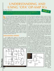
Completed Stingray RobotLeft SideTail EndRight SideFront EndPropeller Robot Control Board4121371118562171516141310891. Propeller P8X32A-Q442. 64 KB EEPROM3. Socketed 5 MHz Crystal4. Right Motor Socket5. Left Motor Socket6. L6205 H-Bridge Driver7. USB Connector8. Battery Pack Socket9. Barrel Jack, 2.1 mm10. Power Good/Fail LEDs11. Dual Switching Power Supply12. Reset Button13. 3-Position Power Switch14. Headers to I/O P0-P2315. Voltage Translators for I/O16. Direct I/O Access Vias17. VIN, 5V, 3.3V Headers18. Ground/Mounting ViasCopyright © Parallax Inc. Stingray Robot (#28980) v1.1 10/6/2009 Page 17 of 26
Control Board DetailsThe Propeller Robot Control Board provides all the necessary base circuits needed to build a very powerfulmid-size robotics platform. The control board has an on-board USB serial interface to facilitate programmingand communication with the Propeller chip. A dual switching supply provides 3.3 V and 5 V @ up to 3 Aeach. The on-board dual full bridge driver makes it possible to directly drive the Stingray’s DC brushed gearmotors with an extra motor controller. The 24 available I/O pins are buffered through three 8-bitbidirectional voltage level translators providing direct 5 V interface capability. Finally, the input voltage cancome from the included battery pack, an aftermarket battery pack or a wall adapter using a standard 2.1mm barrel plug. See below for details of the on-board hardware and connections.Propeller P8X32A-Q44 [ 1 ]The multicore Propeller chip contains 8 cogs (processors) that can operate simultaneously, bothindependently and cooperatively with other cogs, sharing access to global memory and the system clock in around-robin fashion through a central hub. Each cog has access to all 32 I/O pins, with pin states tracked inits own I/O output and direction registers. Each cog also has its own memory, as well as two countermodules and a video generator. See the Propeller Manual and datasheet in the Propeller Tool Help for moreinformation.21364KB EEPROM (P28 – P29) [ 2 ]The AT24C512 EEPROM (see the figure at left) chosen for the Stingray is 64KBinstead of 32KB, allowing for extra memory to store user data. This extramemory could be used for GPS lookup tables, map data or whatever youchoose. This extra 32 KB is not overwritten when programming the EEPROMvia the Propeller Tool software. This means that when you <strong>download</strong> a newprogram to the EEPROM the data in the upper 32K is not lost. The SCL line isconnected to P28 and the SDA line is connected to P29.Socketed Crystal [ 3 ]A 5 MHz crystal is included in the socket next to the Propeller chip. With the included crystal the Propellerchip can run at 5, 10, 20, 40 and 80 MHz. By exchanging the crystal for one of a different value otheroperating frequencies can be achieved. Refer to the Propeller datasheet for more information about usingexternal crystals.L6205 Dual Full Bridge Driver (P24 – P27); Motor Sockets [ 4, 5, 6 ]The L6205 driver is connected to the Propeller chip via I/O pins P24–P27.P24 and P25 control Motor A while P26 and P27 control Motor B.The L6205 used on the Propeller Robot Control Board is a Dual Full BridgeDriver that offers many advantages in comparison to a simple H-Bridgecircuit alone. As a dual driver it can handle two motors at up to 2.8 A(5.6 A peak) with an operating frequency of up to 100 kHz. The L6205also provides non-dissipative over-current protection and thermalshutdown. Internal logic eliminates the possibility of an improperconfiguration of the driver that might cause a short circuit. Connections tothe output of the H-Bridge are made through the Motor A and Motor Bsocket’s connectors (Molex #0351560200).546121Copyright © Parallax Inc. Stingray Robot (#28980) v1.1 10/6/2009 Page 18 of 26
The L6205 inputs are connected to P24 through P27 on the Propeller chip. When the power switch on thecontrol board is set for POWER ON/MOTORS ON, the L6205 is enabled and the outputs are connected to themotors. The truth table for controlling the L6205 is shown below in Table 1. P24 and P25 control the leftmotor while P26 and P27 control the right motor. This table assumes the motors are connected to thecontrol board as defined in the assembly instructions.Table 1: Motor Truth TableP24 P25 P26 P27 Left Motor Right Motor0 0 0 0 Brake Brake1 0 0 0 Reverse Brake0 1 0 0 Forward Brake1 1 0 0 Brake Brake0 0 1 0 Brake Forward1 0 1 0 Reverse Forward0 1 1 0 Forward Forward1 1 1 0 Brake Forward0 0 0 1 Brake Reverse1 0 0 1 Reverse Reverse0 1 0 1 Forward Reverse1 1 0 1 Brake Reverse0 0 1 1 Brake Brake1 0 1 1 Reverse Brake0 1 1 1 Forward Brake1 1 1 1 Brake BrakeNote that it may be more intuitive to look at the table as two groups consisting of P24/P25 and P26/P27. Inthis manner you have 4 possible combinations for each motor as shown in Table 2.Table 2P24 P25 Left Motor P26 P27 Right Motor0 0 Brake 0 0 Brake1 0 Reverse 1 0 Forward0 1 Forward 0 1 Reverse1 1 Brake 1 1 BrakePulse-width modulating one of the inputs in the opposite state of the other pin will cause that motor to moveat a speed proportional to the duty cycle of the signal. A wide range of frequencies could be used for pulsewidthmodulating DC brushed motors.The USB Serial Interface (P30 – P31)The USB interface (see the figure at right) provides a serial connection to thePropeller chip through the USB port of your PC. This interface is used for bothprogramming and communication with the control board and is based on the FTDIFT232RL. A green LED indicates data coming into the control board and a red LEDindicates data being sent to the PC. Data coming into the control board goes to P31on the Propeller chip while data being sent comes from P30.72Copyright © Parallax Inc. Stingray Robot (#28980) v1.1 10/6/2009 Page 19 of 26
Battery Pack Socket [ 8 ] and Barrel Jack Connector [ 9 ]The Battery Pack Socket accepts the connector on the StingrayBattery Pack. The Barrel Jack Connector is for use with a 6-15 VDCwall-mount power supply, with a center positive 2.1 mm barrelconnector. NOTE: Using the Barrel Jack Connector temporarilydisables the Battery Pack Socket.CAUTION: The input voltage (VIN) is also the motor voltage.For this reason you should not use a wall adapter or battery higherthan 7.5 VDC when enabling the motors (power switch moved to thethird (right) position, see below). Voltages higher than 7.5 VDC canseverely reduce the life of the motors and potentially damage them.1089Power Good/Fail Indicator LEDs [ 10 ]There are actually two LEDs for power indication on the control board, one red and one green (see thefigure above). The green LED means the power is good. If the input voltage falls below approximately 6VDC the green LED goes out and the red LED above it comes on. You may also notice when switching thepower on/off that the red LED briefly blinks while the power supply rails stabilize.11LT3501-based Dual Switching Supply [ 11 ]The power supply uses the LT3501 Dual Tracking 3 A Switching Regulatorto provide the 3.3 V and 5 V used on the control board. This supplyregulates the 6 – 15 VDC on the input down to the desired voltages at upto 3 A of current per supply.Reset Button [12]This button resets the Propeller chip, initiating its boot up procedure (seethe Propeller Help). Be aware that if the motors are running, this will causethem to go into brake mode (see Table 1 on page 19).3-position Power Switch [ 13 ]The first (left) position, marked ALL OFF, turns off power to the Control Board, I/O13headers when set to 5 V, and motors. In this position the power LED is out. Thesecond (middle) position, marked POWER ON / MOTORS OFF, turns on power to thecontrol board and I/O headers, but disables the H-Bridge, effectively turning themotors off. The last (right) position on the power switch, marked POWER ON /MOTORS ON, turns on power to the control board, I/O headers and motors. Notethat the 3-position switch has no effect on VIN availability at the I/O headers set toVIN, nor at the VIN power supply tap (see VIN, 5 V, and 3.3 V Power AccessHeaders [ 17 ] on page 21).Headers to 24 Available I/O Pins (P0 – P23) [ 14 ]; Voltage Translators [ 15 ]The 24 available I/O pins are connected to three TXB0108 8-bit bidirectional voltage level translators thatconvert the voltage from 3.3 V at the Propeller chip to 5 V at the I/O headers and provides some shortcircuit protection with built-in 4 kΩ resistors. These fully bidirectional pins are grouped as three ports witheight I/O lines each: P0–P7, P8–P15 and P16–P23.15148Copyright © Parallax Inc. Stingray Robot (#28980) v1.1 10/6/2009 Page 20 of 26
Each group is brought out to I/O headers. These pins arelabeled W, R and B, referring to the typical colors of a servoextension cable. W (white) is the signal pin, R (red) is thepower pin and B (black) is the ground connection for each port.To the right of each group of I/O headers is a jumper thatallows either 5 V or VIN to be available at the center (power)pin of that group. By default this is set to 5 V for all threegroups. NOTE: When the jumper is in the VIN position the I/Oheaders will have power at the R row regardless of the positionof the power switch.All data at the I/O header signal (W) pins is at 5 V signal levels, however if you should need direct access tothe Propeller chip I/O for 3.3 V interfacing, it is possible to disable a translator and gain direct access to theeight I/O pins connected to it. Doing this requires the addition of some headers which would need to besoldered to the control board. The following section describes how to complete this procedure.NOTE: While a translator has been disabled, all eight I/O pins in that group are affected and cannot beaccessed from the I/O header pins.Direct I/O Access Vias [ 16 ]In the figures below, the control board has had headers soldered into the unpopulated pads above and tothe left of the center translator IC. This will allow you to connect pluggable wires to P8 through P15,however the translator chip itself will interfere unless it is disabled. In the right figure a jumper (also calleda shorting block or shunt) has been placed over the 2-pin header to the left of the translator. Thiseffectively disables the translator and all connections for P8 through P15 at the I/O header. Once atranslator is disabled you can connect directly to the Propeller I/O pins. Always use caution whenconnecting directly to the I/O pins that you’re using the correct signal voltage (3.3 V) and that the I/O pindirection is set properly since there is no additional protection for the I/O lines when connecting directly tothem. Jumper: Parallax #452-00009; 40-pin male/male header: Parallax #451-04001.Translator Enabled8-pin bypass header and 2-pin translator header installed.Jumper not installed.Translator DisabledJumper installed on 2-pin translator header.VIN, 5 V, and 3.3 V Power Access Headers [ 17 ]These sockets provide convenient access to the 3 power rails and can typically be jumpered over to thepower bus on the breadboard using standard jumper wires. NOTE: VIN access on this header always haspower when a power source is connected to the board, regardless of the position of the 3-position switch.Ground/Mounting Vias [ 18 ]The Mounting Vias are sized and positioned to be compatible with many of our popular microcontrollerdevelopment platforms. All four of these holes are connected to the PCB’s ground plane.Copyright © Parallax Inc. Stingray Robot (#28980) v1.1 10/6/2009 Page 21 of 26
Testing CommunicationParts Required• Assembled Stingray Robot• USB A to Mini B Cable• (2) Red LED (from PE Kit Project Parts)• (2) 470 ohm resistor (from PE Kit Project Parts)• (2) Transistor, NPN, Switching, 200 mA• (3) Jumper Wire, F-M, 120 mm, 10-PackDownload and install the latest version of the Propeller Tool Software from the Downloads link atwww.parallax.com/Propeller. Be sure to permit the installation/update of the FTDI USB driversduring installation.Be sure the power switch on the control board is set to ALL OFF.Connect the USB A connector to the PC and the Mini B side to the control board. Your PC shoulddetect a new device and complete the installation of the drivers already available on the PC fromwhen you installed the Propeller Tool if this has not already been done previously.Run the Propeller Tool software. The first time you run the Propeller Tool you may be prompted witha file association dialog box. If so, click ‘Yes” to associate the common extensions for Propellerprograms with the Propeller Tool software.Slide the power switch to the POWER ON / MOTORS OFF(middle) position to turn on the control board. You shouldsee the green power LED light up, as shown at right.ooIf it does not, slide the power switch to ALL OFF toturn the control board off. Double check all yourconnections and try again.If you see a red LED instead this is an indicator thatyour batteries input voltage is below 6V. This usuallyindicates low batteries; replace your batteries.With the control board powered and the Propeller Tool running on your PC press the F7 key toidentify connected hardware. You may also do this from the Propeller Tool menu system by clickingRun → Identify Hardware…The Propeller Tool will scan all COM ports searching for a connectedPropeller chip and display a message similar to the figure at right.Once scanning is complete you will see a message box like the one inthe figure below left if a Propeller chip is detected or like figure belowright if no Propeller chips were found.If you are unable to detect your Propeller chip recheck your connections and try again.If you continue to have difficulty please contact our Tech Support using the resources located at theend of this documentation.Copyright © Parallax Inc. Stingray Robot (#28980) v1.1 10/6/2009 Page 22 of 26
Conserve energy! Be sure to turn off the power when not <strong>download</strong>ing or running a program on the controlboard. This will help conserve batteries and prevent accidents when wiring new circuits or connectingaccessories to the control board.Protect your hardware! You should also turn off power to the board when building a new circuit to preventdamaging any components.Use the LEDS, resistors and pluggable wires to create the circuit shown in schematic below on thebreadboard. The pluggable wires will jumper to the breadboard to make the I/O and groundconnections from the control board locations shown below. Ground can be obtained from thebottom row of pins (marked B) on the I/O headers. P0 and P1 are picked up from the top row(marked W) and are indicated on the silkscreen on the control board. Power is obtained from thecenter row (marked R) and its voltage is set by the jumper immediately to the right of that group ofheaders.Download the example code from the Stingray product page at www.parallax.com.Load the program LED Test.spin into the Propeller Tool.Slide the power switch on the control board to the middle position. The Green power LED shouldlight up. In the Propeller Tool software press the F10 key to <strong>download</strong> the LED Test.spin code tothe control board. If your circuit was wired correctly the two LEDs should start flashing back andforth every second.'' File: LED Test.spinCON_xinfreq = 5_000_000_clkmode = xtal1 + pll16x' External Crystal Frequency' Enabled External Crystal and PLL X16PUB Maindira[1..0] := %11repeatouta[0] := 1outa[1] := 0waitcnt(clkfreq / 2 + cnt)outa[0] := 0outa[1] := 1waitcnt(clkfreq / 2 + cnt)' Set P0 And P1 To Output' P0 HIGH' P1 LOW' Delay 1/2 Clock Frequency (1/2 Second)' P0 LOW' P1 HIGH' Delay 1/2 Clock Frequency (1/2 Second)Once the test has completed, turn the power off and remove the components from the breadboardand disconnect the pluggable wires from the control board.Leave the USB cable and power supply connected as you will need them for the motor test comingup.Copyright © Parallax Inc. Stingray Robot (#28980) v1.1 10/6/2009 Page 23 of 26
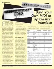
Driving Brushed DC MotorsThis section will guide you through connecting and testing the DC Brushed Gear Motors included with theStingray robot. Familiarizing yourself with the motors included in the Stingray robot kit will help you takeadvantage of the benefits of using these motors as well as understanding the nuances.DC motors are usually driven by an H-Bridge since such a circuit can reverse the polarity of the motorconnected to it. The DC brushed motors included in this kit are driven by the L6205 H-Bridge on thePropeller Robot Control Board. Understanding how to control this H-Bridge is the key to controlling thedirection, speed and duration that the motors are on or off.Parallax has released a Propeller object called, “PWM_32” which makes it easy to drive servos as well ascontrol motors using pulse width modulation. This object can be used with the Propeller Robot ControlBoard to drive the on-board H-Bridge, which in turn drives the DC motors. This object can be <strong>download</strong>edfrom the Stingray robot product page on our website or from the Propeller object exchange listed in theUseful Websites section at the end of this document.Brushed DC Spur-Gear MotorsThe Stingray robot was designed to be fast when needed and as such a method of locomotion was chosento support this requirement. Servo motors used in many smaller robots are too slow and have too little loadcapacity for the Stingray. Instead, brushed DC gear motors were selected. Specifically the motors used areknown as Spur-Gear motors. These motors provide a good value and performance in a reasonably sizedpackage.The motors included in the Stingray kit have the followingspecifications:• 7.2 VDC Nominal @ ~180 mA (no load)• 310 RPM (30:1 gear ratio on output shaft)• 6mm diameter output shaft w/5.5mm detent for hubs withset screws• Output shaft length: 18 mm (0.70”)• Motor shaft extends from back of motor allowing encodersupport• Motor shaft length: 10 mm (0.40”)• Four M3 size mounting holesInternally the Spur-gear motor looks like the picture shown below, left. The back side of the motor is shownin the figure on the right. Take note of the (+) sign that is used to indicate polarity. While motors don’thave a specific polarity per se, the plus signs help to match polarity of the motors on either side so you knowthe direction the motor will turn when you apply power to it. When you apply power to the motor so thatthe positive supply is connected to the (+) terminal and the other terminal connects to ground the internalmotor shaft turns clockwise while the output shaft spins counter-clockwise.Spur-gear motorinternalsBack side of motor; notethe ⊕ symbol to helpmatch polarity.Copyright © Parallax Inc. Stingray Robot (#28980) v1.1 10/6/2009 Page 24 of 26
The motors are designed to run nominally at 7.2 VDC. This voltage was chosen due to the popularity of7.2 V R/C battery packs used as power sources on robots and in R/C cars. Running the motors at voltageshigher than 7.2 V can wear the brushes out quicker, reducing the life of the motor. Keep this in mind if youconnect an external power supply into the Propeller Robot Control Board as the input voltage at the powerconnector is what is fed to the motors through the H-Bridge. Often wall supplies have a higher outputvoltage than what they are rated at when not at their full output current. We recommend our 7.5 V, 1 Apower supply #750-00009.Another thing to keep in mind with DC motors is that two motors of the same model given the same voltagemay not spin at exactly the same speed. This is due to variations in the internal coils, magnets, etc. Similarto calibrating continuous rotation servos, DC motors must be calibrated in software to ensure the robot goesin a straight line. Because the motor shaft extends from the back of the motor you could also employ opticalencoders and program your motor drive code to adjust motor speed based on feedback provided by theencoders, but that is a topic for a future update.Testing the MotorsLoad the programs Left Motor Test.spin and Right Motor Test.spin into the Propeller Tool.Slide the power switch on the control board to the second position (POWER ON/MOTORS ON).Select each program one at a time and <strong>download</strong> it to the Stingray robot by pressing the F10 key.Observe the results. Each motor should rotate forward for two seconds, stop for 2 seconds androtate reverse for 2 seconds.'' File: Left Motor Test.spinCON_xinfreq = 5_000_000_clkmode = xtal1 + pll16xPUB Maindira[27..24] := %1111outa[25] := 1waitcnt(clkfreq * 2 + cnt)outa[25] := 0waitcnt(clkfreq * 2 + cnt)outa[24] := 1waitcnt(clkfreq * 2 + cnt)outa[24] := 0repeat' External Crystal Frequency' Enabled External Crystal and PLL X16' Set P24 Through P27 To Output' Left Motor Forward' 2 Second Pause' Left Motor Stop' 2 Second Pause' Left Motor Reverse' 2 Second Pause' Left Motor Stop'' File: Right Motor Test.spinCON_xinfreq = 5_000_000_clkmode = xtal1 + pll16xPUB Maindira[27..24] := %1111outa[26] := 1waitcnt(clkfreq * 2 + cnt)outa[26] := 0waitcnt(clkfreq * 2 + cnt)outa[27] := 1waitcnt(clkfreq * 2 + cnt)outa[27] := 0repeat' External Crystal Frequency' Enabled External Crystal and PLL X16' Set P24 Through P27 To Output' Right Motor Forward' 2 Second Pause' Right Motor Stop' 2 Second Pause' Right Motor Reverse' 2 Second Pause' Right Motor StopCopyright © Parallax Inc. Stingray Robot (#28980) v1.1 10/6/2009 Page 25 of 26
Troubleshooting the MotorsIf the motors do not respond as expected then the following troubleshooting steps should help you correctmost issues. If none of these troubleshooting steps solves your issue or if your issue is not listed you maycontact our Tech Support using the resources listed at the bottom of this page.Symptom: The motors do not move at all, but the program <strong>download</strong>s successfully.Check: The power switch may be in the POWER ON/MOTORS OFF position instead of POWER ON/MOTORSON.Symptom: The motor rotates in reverse for two seconds, stops for two seconds then rotates forward fortwo seconds.Check: The motor leads may be reversed on the motor. Remove the top plate from the chassis and swapthe wires on the motor terminals for the side that was affected.Symptom: The motor starts to turn forward then stops, then starts to turn forward again.Check: The batteries may be running low. Try a fresh set of batteries.Additional ResourcesResources for the Stingray such as example code are posted to the Stingray product page on our website.Go to our website at www.parallax.com and type the product number (28980) into the search box and clickthe Go button. The example code will be in a ZIP file located under the heading Downloads and Resources.Save the contents of the ZIP file to a known folder for use in later activities in the book. Over timeadditional resources, videos, and accessories will be added so check back often as these will be linked fromthe Stingray product web page.Useful WebsitesIn addition to the resources available on the Stingray product page you can get additional resources such asuseful objects for sensors from the following links:• Propeller Home Page: http://www.parallax.com/propeller• Object Exchange: http://obex.parallax.com• Support/Discussion Forums: http://forums.parallax.com → Propeller ChipTech Support ResourcesParallax Inc. offers several options for obtaining technical support for your product:• Email: support@parallax.com• Fax: (916) 624-8003• Phone: (916) 624-8333 or toll-free in the U.S. at (888) 99-STAMP. Phone support is availableMonday through Friday from 7:00 AM to 5:00 PM Pacific time or you can leave a message and a techsupport representative will return your call as soon as possible.• Forums: http://forums.parallax.com. Our support forums are available 24 hours a day, 7 days aweek and are frequented by both Parallax customers and employees. You can often find fastanswers to questions by searching previous posts or posting your question to the Propeller chipforum.Copyright © Parallax Inc. Stingray Robot (#28980) v1.1 10/6/2009 Page 26 of 26