Build Your Own Midi to Synthesizer Interface - Nuts & Volts Magazine
Build Your Own Midi to Synthesizer Interface - Nuts & Volts Magazine
Build Your Own Midi to Synthesizer Interface - Nuts & Volts Magazine
You also want an ePaper? Increase the reach of your titles
YUMPU automatically turns print PDFs into web optimized ePapers that Google loves.
y Thomas Henry<br />
Flip through any music<br />
or recording magazine<br />
and you’ll find constant<br />
reference <strong>to</strong> the fact<br />
that we’re in the midst<br />
of an analog synthesizer<br />
revival. Indeed, more and<br />
more musicians are dusting off<br />
their favorite instruments of yesteryear<br />
and hauling them in<strong>to</strong><br />
the studio or on<strong>to</strong> the stage<br />
again.<br />
The claim is that these old analog<br />
synthesizers have a richer and warmer<br />
sound than their modern digital counterparts.<br />
The only trouble, though, is<br />
that analog units are voltage-controlled,<br />
whereas virtually all modern<br />
recording and performing equipment<br />
is MIDI based.<br />
MIDI is a standard pro<strong>to</strong>col that<br />
permits the interconnection of a broad<br />
range of musical devices, and then<br />
lets them communicate with each<br />
other via a digital bit stream.<br />
Well, don’t give up on your analog<br />
synthesizer just yet, for here’s the<br />
MTS-100! The MTS-100 is an inexpensive<br />
monophonic MIDI-<strong>to</strong>-<strong>Synthesizer</strong><br />
interface which lets you add digital<br />
control. With it, it’s a snap <strong>to</strong> connect<br />
a modern music keyboard or a personal<br />
computer running sequencer software<br />
<strong>to</strong> your dinosaur.<br />
The MIDI messages coming down<br />
the pike are converted <strong>to</strong> standard<br />
control voltage, gate and trigger formats,<br />
perfect for taming most older<br />
equipment. And just check out these<br />
features:<br />
• MIDI IN and THRU jacks<br />
• 1V/octave control voltage output<br />
• Pitch bend (pitch wheel) control<br />
voltage output<br />
• Independent gate and trigger outputs<br />
for full retriggerability<br />
• Omni on or off switch and indica<strong>to</strong>r<br />
• Channel switch and indica<strong>to</strong>r<br />
• Recognizes a variety of MIDI<br />
Channel Mode messages<br />
• Octave transpose switch extends<br />
response with<br />
short keyboards<br />
• Fits behind an industry standard 1U<br />
rack panel (1-3/4” by 19”)<br />
But if you really want <strong>to</strong> know<br />
what the MTS-100 can do, then check<br />
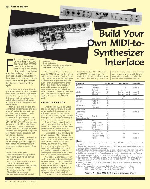
out its Implementation Chart in Figure<br />
1. By cus<strong>to</strong>m, each piece of MIDI gear<br />
is supposed <strong>to</strong> be provided with just<br />
such a chart. It’s really nothing more<br />
than a standardized way <strong>to</strong> explain<br />
what MIDI features are available,<br />
what messages are recognized, etc.<br />
Take a moment <strong>to</strong> review it. After you<br />
get a feel for what <strong>to</strong> expect, then<br />
read on <strong>to</strong> see how the MTS-100<br />
works.<br />
CIRCUIT DESCRIPTION<br />
Since the MTS-100 is really little<br />
else than a glorified digital-<strong>to</strong>-analog<br />
converter (DAC), it’s convenient <strong>to</strong><br />
split the schematic in<strong>to</strong> two main<br />
parts. In broad terms, Figure 2 depicts<br />
the digital side of things, while Figure<br />
3 shows the analog portion.<br />
Refer <strong>to</strong> Figure 2 now. If you’re<br />
getting a sense of deja vu, there’s a<br />
reason! You might recall my ADV-MIDI<br />
project which appeared in the Oct.<br />
’97 issue of <strong>Nuts</strong> & <strong>Volts</strong> <strong>Magazine</strong>.<br />
The purpose of that circuit was <strong>to</strong><br />
convert incoming MIDI messages <strong>to</strong><br />
triggers suitable for firing analog drum<br />
sets. As it turns out, quite a bit of the<br />
input circuitry can be copied over<br />
directly. So, we can really buzz<br />
through the explanation now. The<br />
basics will be described here, but if<br />
you need more details or want <strong>to</strong><br />
refresh your knowledge of MIDI, refer<br />
back <strong>to</strong> the article just mentioned.<br />
A source of MIDI messages (coming<br />
from a music keyboard, sequencer,<br />
personal computer, etc.) is applied <strong>to</strong><br />
jack J5. Op<strong>to</strong>coupler IC1 isolates and<br />
translates the electrical signal as<br />
required by the MIDI specification. A<br />
suitable replica of the bit stream is<br />
generated at output pin 6 of IC1.<br />
One path conducts this bit stream<br />
<strong>Build</strong> <strong>Your</strong><br />
<strong>Own</strong> MIDI-<strong>to</strong>-<br />
<strong>Synthesizer</strong><br />
<strong>Interface</strong><br />
directly <strong>to</strong> input port line PA7 of the<br />
MC68705P3 microprocessor. (For<br />
brevity, this chip will be referred <strong>to</strong> as<br />
the 68705 from now on.) The bits roll<br />
in <strong>to</strong> the microprocessor one at a time<br />
and are properly reassembled in<strong>to</strong> a<br />
complete byte under control of the<br />
firmware residing within the chip.<br />
Function Transmitted Recognized Remarks<br />
Basic Default *** 1<br />
Channel Channel *** 1-16 note 1<br />
Default *** Mode 4<br />
Mode Messages X Modes 2 or 4 note 2<br />
Altered *** Modes 2 or 4 note 3<br />
Note X O<br />
Number True Voice *** 0-127 note 4<br />
Velocity Note ON X X<br />
Note OFF X X<br />
After<strong>to</strong>uch Key X X<br />
Channel X X<br />
Pitch Bend X O<br />
Controllers X O note 5<br />
Program X X<br />
Change True # *** ***<br />
System Exclusive X X<br />
System SPP X X<br />
Common Song Select X X<br />
Tune Request X X<br />
System Clock X X<br />
Realtime Commands X X<br />
Aux Local ON/OFF X ***<br />
All Notes Off X O note 6<br />
Active Sensing X X<br />
Reset X O note 7<br />
Notes:<br />
1. At power-up or during reset, switch S2 can set the MTS-100 <strong>to</strong> receive on any channel<br />
(1-16).<br />
2.The MTS-100 can be set <strong>to</strong> Omni Off or Omni On either by front panel switch S1, or by<br />
an appropriate Channel Mode Message.<br />
3.The MTS-100 is a monophonic device, but is compatible with any MIDI keyboard even if<br />
polyphonic. In this case, it simply responds <strong>to</strong> the most recent Note On message.<br />
4.The MTS-100 can convert all 128 MIDI notes. If using a short keyboard, switch S3 can<br />
transpose notes up or down by one octave <strong>to</strong> extend the output range.<br />
5.The following Channel Mode messages are recognized: Reset All Controllers, All Notes<br />
Off, Omni Off, and Omni On. Reset All Controllers sets the pitch bend output <strong>to</strong> its<br />
midposition value.<br />
6.Sending the Omni Off or Omni On commands also turns all notes off, as required by<br />
the MIDI 1.0 spec.<br />
7.The current channel can be changed during the Reset sequence, if desired.<br />
Mode 1: Omni On, Poly Mode 2: Omni On, Mono O: Yes<br />
Mode 3: Omni Off, Poly Mode 4: Omni Off, Mono X: No<br />
Figure 1 — The MTS-100 Implementation Chart<br />
52 December 1997/<strong>Nuts</strong> & <strong>Volts</strong> <strong>Magazine</strong>
Pin 6 of IC1 also feeds MIDI THRU<br />
jacks J6 and J7 by means of the<br />
buffers configured around IC2c and<br />
IC2d. Again, this is a standard<br />
arrangement described in the MIDI<br />
specification. The MIDI THRU jacks<br />
can be used <strong>to</strong> daisy chain other<br />
equipment <strong>to</strong> the MTS-100.<br />
Since the MIDI messages are<br />
asynchronous in nature (i.e., can<br />
occur at any time), microprocessor<br />
interrupts are used <strong>to</strong> dictate when<br />
data is <strong>to</strong> be read in. Once a message<br />
is rolling in, it is important that the<br />
68705 not be further interrupted.<br />
Thus, IC2b is used <strong>to</strong> pass or block<br />
external interrupts <strong>to</strong> pin 2 of the<br />
68705, as required.<br />
Switch S1 and LED D5 work in<br />
tandem <strong>to</strong> let the user turn Omni<br />
mode on or off from the front panel.<br />
Port line PC2 of the 68705 is normally<br />
high. Tapping pushbut<strong>to</strong>n S1 once<br />
causes this line <strong>to</strong> momentarily drop<br />
low. The microprocessor senses the<br />
change and <strong>to</strong>ggles the condition of<br />
the Omni status, as well as LED D5.<br />
Obviously when the LED is shining,<br />
Omni mode is on, and when it is<br />
dark Omni mode is off. By the way,<br />
you can also turn Omni on or off by<br />
sending the standard MIDI Channel<br />
Mode message. The LED will still<br />
respond as just described.<br />
S2 and D4 also work as a team,<br />
in this case <strong>to</strong> set or test the current<br />
channel. At power-up or during reset,<br />
the channel defaults <strong>to</strong> 1. But you can<br />
change it <strong>to</strong> any legal value (1-16) in<br />
Figure 2 — MTS-100 Schematic 1 of 2<br />
the following way.<br />
First, with power <strong>to</strong> the MTS-100<br />
off, press and hold pushbut<strong>to</strong>n S2.<br />
Now turn the power on. LED D4 will<br />
begin flashing, about once per second.<br />
Simply release the pushbut<strong>to</strong>n<br />
after witnessing the desired number<br />
of blinks, representing the channel.<br />
For example, <strong>to</strong> set the MTS-100 <strong>to</strong><br />
channel 5, hold S2 closed then turn<br />
the power on. After five blinks,<br />
release S2.<br />
Once you’re up and running, you<br />
can also use pushbut<strong>to</strong>n S2 <strong>to</strong> check<br />
what the current channel is, in case<br />
you’ve forgotten it in the meanwhile.<br />
Simply tap the switch once. The LED<br />
will flash the number of times representing<br />
the current channel number.<br />
This is a very simple, yet effective<br />
method <strong>to</strong> set or test the channel.<br />
And best of all, it uses very little front<br />
panel real estate!<br />
Switch S3, which connects <strong>to</strong> the<br />
68705 port lines PC0 and PC1, can be<br />
used <strong>to</strong> transpose the currently played<br />
note up or down by one octave. This<br />
is handy if you are driving the MTS-<br />
100 with a smaller keyboard which<br />
spans less than the 128 notes of the<br />
standard MIDI scheme.<br />
If the lowest note on your keyboard<br />
is number 36, for instance, then<br />
by flipping S3 <strong>to</strong> the minus position,<br />
the internal firmware au<strong>to</strong>matically<br />
subtracts 12 (a one octave difference)<br />
and spits out the number 24 <strong>to</strong> the<br />
Figure 3 — MTS-100 Schematic 2 of 2<br />
<strong>Nuts</strong> & <strong>Volts</strong> <strong>Magazine</strong>/December 1997 53
DAC.<br />
In a similar way, putting<br />
S3 <strong>to</strong> the plus position will<br />
add 12. In effect, your short<br />
keyboard has now gained an<br />
octave on both the low and<br />
high ends. By the way, the<br />
firmware takes care of any<br />
potential goofiness should<br />
you attempt <strong>to</strong> transpose a<br />
note out of range. In this<br />
case, it’s simply left as is and<br />
passed on <strong>to</strong> the DAC<br />
unchanged.<br />
The envelope genera<strong>to</strong>rs<br />
in an analog synthesizer<br />
require a source of keyboard<br />
gate and trigger signals. A<br />
gate should normally be at<br />
0V, but swing <strong>to</strong> +5V and<br />
stay there whenever a note is<br />
<strong>to</strong> be sounded. On the other<br />
hand, a trigger is a 0V <strong>to</strong> +5V<br />
pulse, several milliseconds<br />
wide. It is generated at the<br />
outset of a note, and can<br />
also be retriggered under<br />
certain other conditions.<br />
For example, suppose<br />
you have pressed a key on a<br />
music keyboard for the first<br />
time. A trigger is created.<br />
Now imagine that you keep<br />
that key depressed and play<br />
another one in addition <strong>to</strong> it.<br />
The current note number is<br />
updated <strong>to</strong> the new value of<br />
course, but more importantly,<br />
another trigger is fired off<br />
as well.<br />
What this means is that<br />
the MTS-100, like all good<br />
quality synths from the past,<br />
lets you use the musical technique<br />
known as a “trill.” You<br />
can twiddle an extra note in<br />
addition <strong>to</strong> the currently held<br />
one and the envelope genera<strong>to</strong>r<br />
in the synthesizer will be<br />
au<strong>to</strong>matically retriggered.<br />
By the way, the description<br />
just given implies that<br />
the MTS-100 follows what is<br />
known in music circles as the<br />
“last note rule.” This means<br />
that if you press more than<br />
one key, the unit will always<br />
respond <strong>to</strong> the most recent one. And<br />
of course, there’s no such thing as<br />
“simultaneous” in MIDI, so one of the<br />
notes will always be the most recent!<br />
The gate signal is created by port<br />
line PB0 of the 68705. During quiescence,<br />
this line is high, which keeps<br />
transis<strong>to</strong>r Q2 turned on. This implies<br />
that the tip of jack J2 is at 0V as<br />
expected. (Also notice that LED D3 is<br />
off). But when the line goes low in<br />
response <strong>to</strong> a note number coming in,<br />
D3 shines and J2 goes <strong>to</strong> +5V.<br />
The trigger signal is only slightly<br />
more complicated <strong>to</strong> create. When it’s<br />
time for a trigger, port line PB1 swings<br />
low long enough for LED D2 <strong>to</strong> be<br />
plainly visible. At the same time, C8<br />
and R30 differentiate the pulse, and<br />
Figure 4 — Foil Side of the MTS-100 Printed Circuit Board<br />
Figure 5 — The MTS-100 Circuit Board Parts Placement Guide<br />
There are 15 jumpers. Each is represented as a solid line connecting two points.<br />
Q1 squares it up nice and neat. What<br />
comes out of J1 is a good looking rectangular<br />
waveform, about five milliseconds<br />
wide.<br />
And that pretty much wraps up<br />
the digital side of things in the MTS-<br />
100. Before leaving Figure 2, however,<br />
notice that port lines PA0 through<br />
PA6, and PB4 and PB5 haven’t been<br />
accounted for yet. They’ll resurface as<br />
we investigate how the analog portion<br />
of the MTS-100 works. So let’s move<br />
on.<br />
Turn your attention <strong>to</strong> Figure 3<br />
now. When a note number is received<br />
by the 68705 from the MIDI input, it<br />
is transferred <strong>to</strong> IC4 via port lines PA0<br />
through PA6. Notice that one of the<br />
bit inputs of the DAC (pin 5) is tied <strong>to</strong><br />
ground and not used. This is because<br />
the MIDI spec dictates that note numbers<br />
should run from 0 <strong>to</strong> 127, which<br />
only requires seven bits <strong>to</strong> represent.<br />
The DAC needs a stable current<br />
reference for operation. So, resis<strong>to</strong>r<br />
string R6, R28, and R29 first create a<br />
tapped voltage. R28 is actually a trimmer<br />
potentiometer. This will let you<br />
tweak the MTS-100 for a precise<br />
1V/octave response. (Virtually all of<br />
the better analog synths follow this<br />
standard). Electrolytic capaci<strong>to</strong>r C18<br />
stabilizes things a bit. But more importantly,<br />
the follower composed of opamp<br />
IC6b buffers the tapped voltage<br />
and provides a good, low-impedance<br />
output source.<br />
The voltage at the output of IC6b<br />
is converted <strong>to</strong> a current by<br />
R14, which then feeds the<br />
positive reference input of the<br />
DAC at pin 14. Incidentally,<br />
R15 is of the same value and<br />
is used <strong>to</strong> balance the negative<br />
reference input at pin 15<br />
of IC4.<br />
The output of the DAC is<br />
a current; it flows from pin 4.<br />
This needs <strong>to</strong> be converted <strong>to</strong><br />
a voltage before proceeding<br />
and that is the purpose of R25<br />
and IC6a. As mentioned earlier,<br />
the voltage will follow a<br />
1V/octave response.<br />
Now comes the interesting<br />
part. You will probably be<br />
interfacing a music keyboard<br />
<strong>to</strong> the MTS-100 for much of<br />
your work. Most modern keyboards<br />
have a pitch wheel on<br />
them. By bobbling this wheel,<br />
you can bend the pitch of the<br />
currently played note up or<br />
down. We definitely want the<br />
MTS-100 <strong>to</strong> take advantage<br />
of this neat feature. But<br />
won’t that require an additional<br />
DAC Nope, not if we<br />
use a multiplexing scheme!<br />
Here’s the basic concept.<br />
The DAC will share its time<br />
between two separate sample-and-hold<br />
(S/H) circuits. At<br />
one instant, it s<strong>to</strong>res the control<br />
voltage in the first S/H,<br />
and in the next instant it<br />
s<strong>to</strong>res the pitch bend voltage<br />
in the second. Then the<br />
process starts over again.<br />
Since the multiplexing is happening<br />
at such a rapid rate<br />
(about 100 microseconds per<br />
cycle), the S/H capaci<strong>to</strong>rs<br />
never have a chance <strong>to</strong> drop<br />
or lose their s<strong>to</strong>red charges.<br />
The net effect The DAC<br />
appears <strong>to</strong> have two separate<br />
outputs. Let’s look in<strong>to</strong> the<br />
details.<br />
The output voltage of<br />
the DAC is found at pin 3 of<br />
IC6a, the op-amp follower.<br />
This signal splits in two now,<br />
going <strong>to</strong> analog switches<br />
IC5a and IC5b. When switch<br />
IC5a is closed, the DAC voltage is<br />
applied <strong>to</strong> the S/H configured around<br />
C9 and IC6c. The buffered voltage is<br />
then presented <strong>to</strong> jack J3, the control<br />
voltage output. On the other hand, if<br />
IC5b is closed then the DAC’s output<br />
is instead routed <strong>to</strong> C10 and IC6d.<br />
The buffered pitch bend voltage is<br />
available at jack J4.<br />
In case you’re wondering, the<br />
firmware within the 68705 makes certain<br />
that only one of these analog<br />
switches is closed at any given<br />
moment. Another thing <strong>to</strong> note is that<br />
the CMOS switches need <strong>to</strong> operate<br />
off of a +15V power supply. This is<br />
because the voltage from the DAC<br />
ranges on up <strong>to</strong> +10.58V (note number<br />
127). So transis<strong>to</strong>rs Q3 and Q4,<br />
54 December 1997/<strong>Nuts</strong> & <strong>Volts</strong> <strong>Magazine</strong>
Figure 6 — Front Panel<br />
Figure 7 — Front Panel Drilling Guide<br />
along with their associated<br />
resis<strong>to</strong>rs, translate the<br />
TTL control signals from<br />
the 68705 <strong>to</strong> a suitable<br />
+15V level.<br />
To wrap things up,<br />
notice that there have<br />
been numerous capaci<strong>to</strong>rs<br />
not mentioned in<br />
the circuit description so<br />
far. Most of these are<br />
decoupling, bypass, or<br />
compensation caps. In<br />
general, these caps are<br />
used <strong>to</strong> stabilize the<br />
operation of the various<br />
chips. Even though they<br />
don’t seem <strong>to</strong> do anything<br />
very glamorous, all<br />
of them are essential for<br />
proper performance.<br />
Well, you’re probably<br />
sick of circuit descriptions,<br />
so let’s move on<br />
now and see how <strong>to</strong><br />
actually construct the<br />
MTS-100!<br />
BUILD IT!<br />
Besides the hardware<br />
just described, it<br />
also takes firmware <strong>to</strong> put the MTS-<br />
100 through its paces. If you’d like <strong>to</strong><br />
try a complete homebrew approach,<br />
then first obtain a blank 68705 chip.<br />
Jameco Electronics (1355 Shoreway<br />
Road, Belmont, CA 94002) is a good<br />
source for the part, and has them for<br />
under $15.00.<br />
Next, you’ll need <strong>to</strong> get your<br />
hands on the program for the<br />
firmware. Even though the object<br />
code is quite short (about 700 bytes),<br />
it’s still <strong>to</strong>o long <strong>to</strong> appear in this article.<br />
However, the complete annotated<br />
assembler source code is available free<br />
of charge for download on the World<br />
Wide Web. See the Parts List for<br />
details.<br />
Next, you’ll need <strong>to</strong> assemble the<br />
code and burn it in<strong>to</strong> your chip. There<br />
are dozens of excellent freeware and<br />
shareware cross-assemblers available<br />
on the Internet; try your favorite<br />
search engine and see! As for programming<br />
the microprocessor, get<br />
your hands on a 68705 Mo<strong>to</strong>rola<br />
manual. You’ll find complete directions<br />
for programming the internal<br />
EPROM.<br />
But if the thought of hassling<br />
around with software doesn’t appeal<br />
<strong>to</strong> you, then you might want <strong>to</strong> consider<br />
purchasing the kit of parts which<br />
includes a programmed 68705. Refer<br />
<strong>to</strong> the Parts List for ordering information.<br />
All of the other components in<br />
the MTS-100 are available from a variety<br />
of sources. A quick check of the<br />
ads in this magazine or the catalogs<br />
of some of the better mail order houses<br />
will fill in the gaps almost immediately.<br />
After gathering the parts <strong>to</strong>gether,<br />
ponder what method of construction<br />
you will employ. Most of the project<br />
is non-critical, but keep in mind<br />
that the S/H circuits, as well as the<br />
crystal oscilla<strong>to</strong>r, demand neatness.<br />
(Stray capacitance and the like can<br />
wreak havoc.) So, if you decide <strong>to</strong><br />
handwire it, be sure you keep everything<br />
nice and tidy.<br />
The best approach by far, however,<br />
is <strong>to</strong> use a printed circuit board.<br />
This is much more fun <strong>to</strong> put <strong>to</strong>gether,<br />
looks pretty, and will probably minimize<br />
any potential wiring errors. Many<br />
hobbyists are becoming old hands at<br />
etching their own boards nowadays<br />
using a laser printer and iron-on transfer<br />
material. If you’d like <strong>to</strong> give it<br />
whirl, refer <strong>to</strong> Figure 4 which shows<br />
the 1:1 positive artwork for the foil<br />
side. Conveniently, it all fits on a 4” by<br />
6” board, which is a standard copper<br />
clad size.<br />
See Figure 5 for the<br />
parts placement guide.<br />
Loading the board is pretty<br />
straightforward as long<br />
as you obey the usual<br />
rules. For example, be<br />
sure <strong>to</strong> observe the orientations<br />
of all of the polarized<br />
components. Diode<br />
D1 is marked with a standard<br />
schematic symbol. A<br />
plus sign indicates the<br />
positive lead of electrolytic<br />
capaci<strong>to</strong>rs C14-C18. The<br />
emitter, base, and collec<strong>to</strong>r<br />
leads of Q1-Q4 are<br />
called out with their initial<br />
letters.<br />
Finally, don’t forget <strong>to</strong><br />
install the 15 jumpers.<br />
Figure 8 These are indicated as<br />
straight lines connecting<br />
pairs of points on the diagram.<br />
After loading the<br />
printed circuit board, you<br />
can then proceed <strong>to</strong> the<br />
final wiring of the front<br />
panel. A rack-mounted<br />
unit is perhaps best, since<br />
most pro equipment<br />
comes that way nowadays.<br />
The MTS-100 fits nicely behind a<br />
standard 1U rack panel (1-3/4” by<br />
19”). Figure 6 shows a sample design,<br />
while Figure 7 gives the related drilling<br />
guide. The circuit board mounts<br />
behind the panel on standoffs or little<br />
angles, using #4 hardware <strong>to</strong> secure<br />
things.<br />
To connect the circuit board <strong>to</strong><br />
the panel, notice that all of the relevant<br />
pads are labeled on the parts<br />
placement guide in Figure 5. Even so,<br />
here are a few additional tips. For best<br />
results, twisted triples should be used<br />
<strong>to</strong> connect up jacks J5-J7. The<br />
schematic in Figure 2 shows the pin<br />
arrangement of these jacks, as seen<br />
from the solder lug side. Notice that<br />
G, the ground wire of the triple going<br />
<strong>to</strong> the MIDI input, does not connect<br />
<strong>to</strong> J5. Clip if off, and let it float.<br />
The MTS-100 can<br />
easily interface a<br />
MIDI instrument —<br />
such as a music keyboard<br />
or a computer<br />
running sequencer<br />
software — with<br />
most any analog<br />
synthesizer.<br />
<strong>Nuts</strong> & <strong>Volts</strong> <strong>Magazine</strong>/December 1997 55
The purpose of this wire is simply<br />
<strong>to</strong> provide a degree of shielding for<br />
the other two wires in the triple. It is<br />
left unconnected at the panel side <strong>to</strong><br />
avoid ground loop problems.<br />
On the other hand, G does connect<br />
<strong>to</strong> MIDI THRU jacks J6 and J7.<br />
Solder the respective ground wire of<br />
each triple directly <strong>to</strong> pin 2 of each of<br />
these.<br />
Switches S1-S3 are daisy chained,<br />
with a final lead running back <strong>to</strong> one<br />
of the digital ground pads on the printed<br />
circuit board. The ground lugs of<br />
jacks J1-J4 are also daisy chained, with<br />
their final run going <strong>to</strong> one of the analog<br />
ground pads. (You’ll see why there<br />
are separate digital and analog<br />
grounds in just a moment.) Finally, the<br />
anodes of LEDs D2-D5 are daisy<br />
chained back <strong>to</strong> one of the +5V pads.<br />
The remaining connections <strong>to</strong> the<br />
switches, LEDs, and jacks are trivial,<br />
and easily identified from the designations<br />
on the parts placement guide.<br />
At this point, you should have<br />
only five more pads <strong>to</strong> hook up: digital<br />
ground, +5V, -15V, analog ground,<br />
and +15V. They connect <strong>to</strong> your<br />
power supplies. Notice that these are<br />
standard synthesizer voltages, so you<br />
may be able <strong>to</strong> tap them from an<br />
existing supply. Plan on drawing about<br />
120mA from the +5V supply, 10mA<br />
from the -15V side, and 15mA from<br />
the +15V side.<br />
Connect up these last five lines.<br />
Now here is an easily overlooked, but<br />
vital point <strong>to</strong> remember. In any hybrid<br />
analog/digital circuit, it is essential<br />
that digital ground and analog ground<br />
connect at one point only! This helps<br />
<strong>to</strong> minimize interference and other<br />
gremlins. So, complete the hook-up by<br />
joining digital ground <strong>to</strong> analog<br />
ground right at the output of the<br />
power supplies.<br />
For emphasis, this is the only<br />
place where the two grounds connect<br />
(not at the circuit board and not at<br />
the front panel). If you’ve followed<br />
these directions carefully, then you<br />
should be all set. Give your handiwork<br />
a once over and, if it looks good, then<br />
proceed!<br />
MAKING MUSIC WITH THE<br />
MTS-100<br />
Before you can make music with<br />
your new system, you need <strong>to</strong> calibrate<br />
the voltage response of the<br />
MTS-100. Here’s a quick way <strong>to</strong> do it.<br />
The firmware has been programmed<br />
so that at power up, the current note<br />
defaults <strong>to</strong> number 60 (middle C). This<br />
corresponds <strong>to</strong> a control voltage of<br />
+5V. So simply turn on the power supply,<br />
and moni<strong>to</strong>r the CV output at jack<br />
J3 with a digital voltmeter. Adjust trimmer<br />
potentiometer R28 until you<br />
obtain a reading of +5V.<br />
By the way, most electronic components<br />
need a “break in” period, so<br />
you might want <strong>to</strong> tweak this up several<br />
hours later after the parts have<br />
aged a little.<br />
That’s it; you’re all set <strong>to</strong> go! So,<br />
dig out your analog synthesizer and<br />
connect it up <strong>to</strong> an audio amplifier.<br />
Next, patch in the MTS-100 using<br />
1/4” phone plug cables. Depending<br />
on the modules in your synthesizer,<br />
there may be several ways <strong>to</strong> do this.<br />
Then decide how you will drive the<br />
MTS-100; a music keyboard is the easiest<br />
for your initial testing. Naturally,<br />
you will need <strong>to</strong> use some standard<br />
MIDI cables for this. Figure 8 shows<br />
the details of a simple set-up, just <strong>to</strong><br />
get you started.<br />
Commence your testing by pressing<br />
the Omni but<strong>to</strong>n; confirm that the<br />
Omni LED lights up. Now start playing<br />
some notes on your keyboard. The<br />
Gate and Trigger LEDs should flash,<br />
letting you know that keys are being<br />
detected. Next, turn up the amplifier<br />
and play a few scales.<br />
Now rotate the pitch wheel on<br />
your keyboard. Confirm that the VCO<br />
sweeps up or down appropriately.<br />
<strong>Your</strong> VCO input should have a pot on<br />
it, so dial in the amount sweeping<br />
action you like best. For example, you<br />
might want <strong>to</strong> attenuate the pitch<br />
bend so that a complete rotation covers<br />
only an octave.<br />
Now shut off the MTS-100 and<br />
turn it on again, as you set it for a<br />
new channel. This was described earlier<br />
in the article. Follow this by pressing<br />
the Channel but<strong>to</strong>n one more time<br />
<strong>to</strong> confirm that the LED properly indicates<br />
the number you just chose.<br />
Lastly, hook up your personal computer<br />
<strong>to</strong> the MTS-100. Of course, you’ll<br />
need a MIDI port on the PC <strong>to</strong> do this.<br />
But remember that I described a do-ityourself<br />
Sound Blaster 16 <strong>to</strong> MIDI interface<br />
in the April ’97 issue of <strong>Nuts</strong> &<br />
<strong>Volts</strong> <strong>Magazine</strong>. This puts a MIDI port<br />
within reach of most everyone.<br />
While running some sequencer<br />
software, experiment by sending various<br />
MIDI control messages. You should<br />
be able <strong>to</strong> turn Omni on and off, reset<br />
the pitch bend <strong>to</strong> its mid position value,<br />
turn off stuck notes, and do a complete<br />
system reset. Refer <strong>to</strong> the<br />
Implementation Chart in Figure 1 for<br />
details. If you’ve passed these tests,<br />
then you’re all set <strong>to</strong> resuscitate that<br />
old dinosaur. You will now have the<br />
best of two worlds: the fat sound of<br />
an analog synthesizer, all under MIDI<br />
control! NV<br />
Acknowledgments: I am extremely<br />
grateful <strong>to</strong> John Simon<strong>to</strong>n of PAiA<br />
Electronics, whose pioneering work in<br />
computers and synthesizers made this<br />
design all that much easier <strong>to</strong> accomplish.<br />
I also wish <strong>to</strong> thank Bernie<br />
Hutchins, publisher of the legendary<br />
ELECTRONOTES newsletter, for putting<br />
up with way <strong>to</strong>o many questions, and<br />
patiently helping me track down circuit<br />
goblins.<br />
PARTS LIST<br />
All resis<strong>to</strong>rs are 1/4-watt, 5% values.<br />
R1 - R6 220 ohms<br />
R7 - R10 470 ohms<br />
R11, R12 1K<br />
R13 1.2K<br />
R14, R15 1.8K<br />
R16 - R22 4.7K<br />
R23 - R27 10K<br />
R28 10K trimmer potentiometer<br />
R29 22K<br />
R30 100K<br />
R31 220K<br />
All capaci<strong>to</strong>rs are 16V.<br />
C1<br />
22 pF dipped silver mica<br />
C2 - C7 0.01 mfd disc<br />
C8 - C10 0.047 mfd mylar<br />
C11 - C13 0.1 mfd disc<br />
C14 1 mfd electrolytic<br />
C15 - C17 10 mfd electrolytic<br />
C18 100 mfd electrolytic<br />
Semiconduc<strong>to</strong>rs<br />
D1<br />
1N914 or 1N4148 diode<br />
D2 - D5 Red LED<br />
Q1 - Q4 2N3904 NPN transis<strong>to</strong>r<br />
IC1<br />
6N138 op<strong>to</strong>coupler<br />
IC2<br />
74LS00 quad NAND gate<br />
IC3<br />
MC68705P3 MPU (programmed)<br />
IC4<br />
DAC0800 D-<strong>to</strong>-A converter<br />
IC5<br />
4016 quad SPST switch<br />
IC6<br />
4136 quad op-amp<br />
Other components<br />
X1<br />
4 MHz crystal<br />
S1, S2 SPST pushbut<strong>to</strong>n switch<br />
S3<br />
SPDT (on-off-on) <strong>to</strong>ggle switch<br />
J1 - J4 1/4” phone jack<br />
J5 - J7 Five-pin DIN jack (180 degrees)<br />
Miscellaneous: printed circuit board, LED holders, IC sockets,<br />
front panel, wire, solder, etc.<br />
ORDERING INFORMATION<br />
A kit of parts for the MTS-100 is available from the source<br />
below. Included with the kit is an etched, drilled, and tinned<br />
printed circuit board, programmed microprocessor, all resis<strong>to</strong>rs,<br />
capaci<strong>to</strong>rs, semiconduc<strong>to</strong>rs, crystal, switches, jacks, LED<br />
holders, sockets, and Assembly Guide. Does not include front<br />
panel, wire, or solder.<br />
• MTS-100 Kit (#K210)-$69.95<br />
US and Canadian orders add $5.00 shipping and handling. E-Mail or write<br />
for shipping information <strong>to</strong> other countries.<br />
Prices shown in USA dollars. Remit US funds only. Money orders and<br />
checks only. MN residents add 6.5% sales tax. Prices and terms subject <strong>to</strong><br />
change without notice.<br />
Order from: Midwest Analog Products<br />
P.O. Box 2101<br />
N. Manka<strong>to</strong>, MN 56003<br />
The complete source code for the MTS-100 firmware may be downloaded<br />
free of charge from the WWW homepage of Midwest Analog Products.<br />
WWW:http://prairie.lakes.com/~map<br />
E-Mail: map@prairie.lakes.com<br />
56 December 1997/<strong>Nuts</strong> & <strong>Volts</strong> <strong>Magazine</strong>


