INVASION OF THE CHIPKIT MAX32 - Nuts & Volts Magazine
INVASION OF THE CHIPKIT MAX32 - Nuts & Volts Magazine
INVASION OF THE CHIPKIT MAX32 - Nuts & Volts Magazine

You also want an ePaper? Increase the reach of your titles
YUMPU automatically turns print PDFs into web optimized ePapers that Google loves.
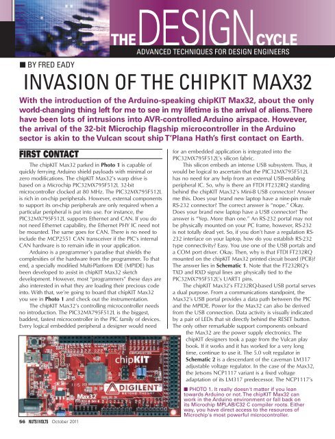
www.nutsvolts.com/index.php?/magazine/article/october2011_DesignCycleDESIGN CYCLE■ SCHEMATIC 1. There's no reason to put a regulation nine-pin RS-232 interface here if your PC has to beadapted to use it. The inclusion of the FT232RQ and a physical USB interface is a perfectly logical choice.■ SCHEMATIC 2. You can feed the NCP1117 from a wall wart or bypass it all together.The idea is five volts in and 3.3 volts out no matter what.job is to bring the raw chipKIT Max32 input voltage (7 to 15VDC) down to an acceptable level (under six volts) for theMCP1725. The NCP1117 is a low dropout version of thestandard LM317 and has a lower dropout voltage than itscontemporary, the LM1117. In addition, the NCP1117 cansupply 1.0 amperes of current versus the 800 mA offered bythe LM1117. The “MCP” tells us that the 3.3 volt MCP1725low dropout voltage regulator is a Microchip product. TheMCP1725’s entourage includes a minimum of relativelysmall and inexpensive stabilizing components. In fact,capacitors C17, C21, and C26 in Schematic 2 are notmounted on the chipKIT Max32 PCB. The big picture is touse the NCP1117 to drop the input voltage to anacceptable level for presentation to the MCP1725 whichwill provide a very stable 3.3 volts at up to 500 mA for theMax32’s PIC32MX795F512L and 3.3 volt peripherals.The NCP1117’s role depends on you. You can feed theNCP1117 from a wall wart, an external power supply, ortotally ignore it by way of the POWER SELECT jumper. The5.0 volts supplied by the NCP1117 to the MCP1725 canalso be usurped by a host PC’s USB portal. As you can seein Schematic 2, a Microchip MCP6001 comparator samplesthe voltages presented at the VCMP voltage divider junctionand VCC3V3 output of the MCP1725. The output of theMCP6001 comparator drives the gate of a P-channelMOSFET which blocks or passes the USB portal’s 5.0 voltsto the VCC5V0 output. The comparator hookup makes surethat the external input voltage always wins the powersourcing battle when a USB power source is attached. Ifyou’re wondering why we need +5.0 volts other than tofeed the MCP1725, it’s the shields, Scotty, the shields.Many of the native AVR-based shields want to see a 5.0 voltpower source. The chipKIT Max32 is designed to becompatible with Arduino shields. The Max32 digital I/O pinsare five volt tolerant. However, the PIC32MX795F512L’sanalog-capable pins are not five volt tolerant. To keep themagic smoke contained within the PIC silicon, every PICanalog-capable pin is protected by a clamp diode andOctober 2011 57
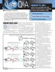
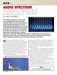
■ SCREENSHOT 1. A jumper between the chipKIT Max32'sA0 analog-to-digital input and +3.3 volts maxes out thePIC32MX795F512L's 10-bit analog-to-digital converter.current limiting resistor. Regardless of the protection, themaximum analog input voltage remains at +3.3 volts.Scanning the Max32 landscape does not reveal any Area 51PIC32MX795F512L programming hardware. Instead, thestandard set of six ICSP pads lie between the power connectorand USB Mini-B interface. The ICSP pads are configured tointerface directly to a PICkit3 programmer/debugger. If youaccidentally find a way to eliminate the factory-loadedbootloader, the ICSP pads and an externalPIC32MX795F512L programmer are the only way to reloadthe bootloader code. The ICSP portal is also your door toloading and debugging your home-grown PIC code.The Max32 physically presents us with 83 I/O pins,16 analog inputs, a 10 Mbps/100 Mbps Ethernet MAC, aUSB 2.0 Full Speed OTG (On The Go) controller, a pair ofCAN controllers, RS-232 modem control handshakingsignals (DCD, CTS, etc.), an SPI portal interface, and apower portal. The length of the Max32 I/O access listtranslates into a gaggle of associated I/O pins and femaleheaders. Fortunately for us, the Arduino boilerplatelogically sorts them all out for us. The Max32 providesfemale headers that supply power to the shields andestablish data paths between the shield electronics andthe PIC32MX795F512L. The Arduino system dictates thatthe Max32 I/O pins range from zero to 85. Each I/O andanalog input is clearly identified by silkscreen legend.We’ve walked around, on, and over most every majorcomponent that comprises the base chipKIT Max32. It’stime to take our Max32 out of space dock and do somemaneuvering.OUT-<strong>OF</strong>-<strong>THE</strong>-BOX ARDUINOYour Max32 will come preloaded with a bootloader58 October 2011and a simple LED blinker application. Igrew out of the LED blinker programrather quickly and decided to try out theMPIDE and Max32 with a simple analogto-digital(A-to-D) application. So, I startedthe MPIDE, selected the Max32 as mytarget platform, and loaded theAnalogReadSerial example sketch.Arduino is an intuitively obvioussystem. So, I won’t insult your intelligencewith a blow-by-blow description of how Iloaded and ran the example program.Everything you need to see concerningmy test run is displayed in Screenshot 1. Iplaced a jumper between the Max32’sA0 A-to-D input and the 3.3 volt powerpin on J10. The PIC32MX795F512L’s A-to-D subsystem has 10 bits of resolution,and the 1023 decimal (0x3FF) result iswhat one would expect to see. I used theMPIDE’s serial monitor tool to display theA-to-D readings in Screenshot 1.Running those simple Arduino demos was enough toconvince me that the PIC32MX795F512L could trulyspeak Arduino. I’ll leave it to you to experiment with theMax32 at this level. If you’re new to Arduino or thePIC32MX795F512L, I suggest stopping here, whipping outyour Max32 hardware, firing up your copy of MPIDE, anddoing some getting acquainted. You’ll find lots of Max32-adapted Arduino example code within the MPIDEframework. Once you get comfortable with the Max32and Arduino, you can pick up and continue from here.<strong>THE</strong> ULTIMATE chipKIT Max32 SHIELDBack in my corporate days, I was the communicationsspecialist for our sales team. My sales pitches were purelytechnical and focused on the importance of setting upand maintaining a robust data network. I would alwaysemphasize the point that no matter how big, how fast, orhow expensive the CPU was, it was a useless piece ofjunk if it could not communicate with its peers and slavesvia some sort of network. The same axiom holds true forsmall embedded devices like the Max32. With thatnetworking thought in mind, get an eye full of Photo 2.Recall that Ethernet PHY IC we mentioned earlier? It’shere. Remember that pair of MCP2551 CAN transceiversthat were needed for the Max32 to participate in a CANnetwork mount? They’re here too. The chipKIT NetworkShield is an extension of the PIC32MX795F512L’s internalcommunications subsystems. By fitting the Network Shieldto the Max32’s female headers, we gain total access tothe PIC32MX795F512L’s 10 Mbps/100 Mbps Ethernetengine and its CAN networking subsystem. The EthernetPHY is made up of an SMSC LAN 8720 PHY IC and a BelStewart MagJack. The chipKIT Network Shield sourceseverything the PIC32MX795F512L’s Ethernet MACrequires, right down to the 25 MHz crystal. The Ethernet
DESIGN CYCLE■ PHOTO 2. The chipKIT Network Shield complements thePIC32MX795F512L's internal communications subsystemsby providing the physical means to access them.PHY portion of the Network Shield is graphically depictedin Schematic 3.The MCP2551 CAN transceiver circuits are inked inSchematic 4. Note that the transceivers require a +5.0 voltsupply. If you’re CAN challenged, those 120Ω resistors areCAN termination resistors. The termination resistors resideat each end of the CAN network. Portals for accessing theI 2 C bus and an onboard 24LC256 I 2 C EEPROM are alsorevealed by the installation of the Network Shield. If youplan to use your Shield in an I 2 C network, you must usebus pull-up resistors in accordance with the I 2 Cspecification. Note the 2.2KΩ pull-up resistors on the24LC256 SCL and SDA lines in Schematic 5.To utilize the PIC32MX795F512L’s internal RTCC(Real Time Clock Calendar), all we really need from ahardware point of view is a 32.768 kHz clock source. TheNetwork Shield is loaded with a 32.768 kHz crystaloscillator which we can use to keep up with the time anddate. The Network Shield is equipped with a pair of USBinterfaces. The Max32 can be configured as a USB host, aUSB device, or a USB OTG device. When configured toact as a USB host, the Network Shield must have a meansof supplying +5.0 volts at the USB host interface. Take alook at Schematic 6. The TPS2051B is a solid-state powerswitch that is under the control of the Max32’s VBUSONsignal. When the TP2051B’s EN input is logically high,VCC5V0 flows to the TP2051B’s OUT pin. The TP2051B’sOUT pin voltage is manually directed to one of the USBinterfaces via a jumper. An overcurrent condition isreported to the PIC32MX795F512L via the TP2051B’sactive-low OC pin. We’ve established one thing forcertain: the Max32 loaded with a Network Shield isdefinitely not a piece of junk. The Max32/Network Shieldcombination has the ability to communicate with mostany embedded or cloud-based computing platform. TheMax32 can even talk to your car.BILINGUAL SILICONThe Max32 was designed to support Arduino with aMicrochip 32-bit microcontroller. However, the Max32and the Network Shield combine to form a perfect PICdevelopment platform. If you want to use the Max32 as adevelopment tool, you’ll need to take control of the■ SCHEMATIC 3. ThechipKIT Network Shieldholds everything thePIC32MX795F512L'sEthernet MAC needs tobecome a full-fledgedEthernet node.October 2011 59
■ SCHEMATIC 4. The MCP2551 CANtransceivers are another reason that the chipKITMax32 provides +5.0 volts to the shields.Loosely translated, the PIC32MXUART Peripheral Library serial transmitlooks like this Arduino statement:Serial.write(0x55);Odds are if you need to transmit,you may also need to receive. In Arduinospeak, receiving data is as easy as:int character;if (Serial.available() > 0){character = Serial.read()}Max32’s FTDI-based USB portal. We’ll do this using thePIC32MX UART peripheral library. The ArduinoSerial.begin(9600); translates to this PIC32MX UARTPeripheral Library snippet:#define GetSystemClock()#define GetPeripheralClock()#define GetInstructionClock()(GetSystemClock() / 2)80000000UL40000000ULUARTConfigure(UART1A,UART_ENABLE_PINS_TX_RX_ONLY);UARTSetLineControl(UART1A, UART_DATA_SIZE_8_BITS| UART_PARITY_NONE | UART_STOP_BITS_1);UARTSetDataRate(UART1A, GetPeripheralClock(),9600);UARTEnable(UART1A, UART_ENABLE_RX_TX);The PIC32MX UART Peripheral Library mnemonicsare self-commenting and are as easy to read and follow asan Arduino sketch. Now that we have the Max32 UART’sattention, sending a byte (0x55) of data is as easy as:if(UARTTransmitterIsReady(UART1A)){UARTSendDataByte(UART1A, 0x55);}Like the Arduino receive code, thePeripheral Library mnemonics are an easyread. There isn’t much difference betweenthe Arduino and the Peripheral Librarycode. As far as the PIC32MX795F512L isconcerned, if you can code in C, you cancode in Arduino, and vice versa:UINT8 character;if(UARTReceivedDataIsAvailable(UART1A)){character = UARTGetDataByte(UART1A);}Whether they are legacy RS-232 or USB-based, serialportals are staples in embedded computing. So, it’s no surprisethat Arduino has a strong set of serial routines in its bag.Some of the Max32 peripherals cannot be accessedbilingually using C and Arduino. However, at this verymoment, there are guys and gals out there porting moreand more PIC32MX code to the Arduino platform.<strong>THE</strong> chipKIT Max32 AND <strong>THE</strong>MICROCHIP APPLICATION LIBRARIESI decided to throw caution to the wind and load upmy Max32 with a Microchip Application Libraries thumbdrive application. Using my PICkit3, I blew up the Max32factory bootloader and replaced it with the Mass Storagesimple demo which is part of the Application Libraries.■ SCHEMATIC 5. If you can't put a finger on that odd crystal, it's nota crystal at all. It's a crystal oscillator that is placed on the chipKITNetwork Shield to drive the PIC32MX795F512L's on-chip RTCC.60 October 2011
DESIGN CYCLE■ SCHEMATIC 6. The PIC32MX795F512L contains all of the USB interfacecircuitry. All that we need to supply are the physical connectors. If our chipKITMax32 is to act in the USB host capacity, throw in a switchable +5.0 volt powersource with those connectors.Here’s the heart of the application://Opening a file in mode “w” will create the file if it// doesn’t exist. If the file does exist it will delete// the old file and create a new one that is blank.myFile = FSfopen(“test.txt”,”w”);//Write some data to the new file.FSfwrite(“Bringing Arduino to the PIC32MX with chipKITMax32”,1,50,myFile);//Always make sure to close the file so that the data gets// written to the drive.FSfclose(myFile);My contribution to the Mass Storage application is rather obvious. Before compilingthe Application Libraries thumb drive code, I set the USB host power jumper tofeed the larger Type A USB connector on the Network Shield and plugged the Shieldinto the Max32. I used the Max32’s Mini-B USB portal to power the Max32/NetworkShield combination from my laptop’s USB portal. Next, I opened the Mass Storageapplication with MPLAB, attached a PICkit3 to the Max32, and compiled thethumb drive application using Microchip’s C32 C compiler. The Application LibrariesMass Storage application is bare bones and doesn’t give any indication that it isworking or not. However, when I attached the thumb drive to the Network Shield’sType A USB connector, the thumb drive’s activity LED began to blink. After afew moments, the thumb drive’s activity LED ceased to blink and remainedilluminated. So, I detached the thumb drive and inserted it into my laptop’s USBportal. Sure enough, there was a file created on the thumb drive called test.txt. Iopened test.txt with a text editor application to find that the file contained thefollowing: Bringing Arduino to the PIC32MX with chipKIT Max32. Enough said.MORE chipKIT Max32 ARDUINO STUFFWe’ve shown the Max32 and Network Shield for what they are: excellentdevelopment tools for both Arduino and native 32-bit PIC32MX applications. If you’vebeen on the fence about a Microchip presence in AVR land, check out the chipKITMax32 forums. I think you’ll be pleasantly surprised. You can access the chipKITforums and purchase your Max32 equipment from the Digilent website (www.digilent.com).Meanwhile, I’ve got some Arduino-to-chipKIT Max32 porting to do! NVOctober 2011 61