A Universal Direct Conversion Receiver For PSK-31 - Nuts & Volts ...
A Universal Direct Conversion Receiver For PSK-31 - Nuts & Volts ...
A Universal Direct Conversion Receiver For PSK-31 - Nuts & Volts ...

Create successful ePaper yourself
Turn your PDF publications into a flip-book with our unique Google optimized e-Paper software.
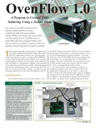
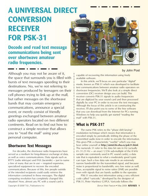
A UNIVERSAL DIRECT<br />
CONVERSION<br />
RECEIVER<br />
FOR <strong>PSK</strong>-<strong>31</strong><br />
Decode and read text message<br />
communications being sent<br />
over shortwave amateur<br />
radio frequencies.<br />
Although you may not be aware of it,<br />
the space that surrounds you is filled with<br />
bursts of text messages speeding to their<br />
destinations. No, we’re not referring to<br />
messages produced by teenagers on their<br />
cell phones trying to link up at the mall,<br />
but rather messages on the shortwave<br />
bands that may contain emergency<br />
communications, announce a special<br />
event, or merely consist of friendly<br />
greetings exchanged between amateur<br />
radio operators located on two different<br />
continents. Read on to find out how to<br />
construct a simple receiver that allows<br />
you to “read the mail” using your<br />
personal computer.<br />
Shortwave Text Messages<br />
<strong>For</strong> decades, the shortwave radio frequencies have<br />
served as a medium for long-distance exchange of data,<br />
as well as voice communications. Data signals such as<br />
RTTY (radio teletype) and FAX (facsimile) — just to name<br />
a few of many that are in use — required expensive,<br />
specialized equipment to recover the encoded<br />
communications. Because of this, few people outside<br />
of the intended recipients could easily retrieve the<br />
information contained in these messages. The digital<br />
computing revolution has completely changed this<br />
situation! Now, almost any PC with a sound card is<br />
capable of recovering this information using freely<br />
available software.<br />
In this article, we’ll focus on one particular “digital”<br />
mode, known as <strong>PSK</strong>-<strong>31</strong> which was developed to facilitate<br />
text communications between amateur radio operators on<br />
shortwave frequencies. We’ll also look at a simple direct<br />
conversion (DC) receiver design you can build. This<br />
receiver converts <strong>PSK</strong>-<strong>31</strong> signals to audio frequencies<br />
that are digitized by your sound card and then processed<br />
digitally by your PC in order to recover the text messages.<br />
Although the focus of this article is on constructing the<br />
receiver, I’ll also point you to some of the free software<br />
that you can download from the Internet for PCs running<br />
Windows to help you quickly get started “reading the<br />
mail” with <strong>PSK</strong>-<strong>31</strong>.<br />
What is <strong>PSK</strong>-<strong>31</strong>?<br />
by John Post<br />
The name <strong>PSK</strong> refers to the “phase shift keying”<br />
modulation technique which means that information is<br />
encoded simply by periodically shifting the phase of the<br />
transmitted audio tone in order to encode the information.<br />
This gives <strong>PSK</strong> a characteristic “warble” which you may<br />
hear online yourself at http://aintel.bi.ehu.es/psk<strong>31</strong>.html.<br />
The numerals <strong>31</strong> refer to the data bit rate in Hz (actually<br />
it’s <strong>31</strong>.25 Hz — an exact 1/256 sub-multiple of the 8 kHz<br />
sample rate commonly used in PC sound cards); a data<br />
rate that is equivalent to what a moderately good typist<br />
can type. Such a low data rate results in an extremely<br />
narrow bandwidth for the transmitted signal, and because<br />
noise is proportional to bandwidth, very low noise as well.<br />
Thus, acceptable signal to noise ratios (SNR) are possible<br />
even with signals that are barely audible to the operator.<br />
<strong>PSK</strong>-<strong>31</strong> encodes text information using a very efficient<br />
code called “varicode,” developed by the designer of<br />
<strong>PSK</strong>-<strong>31</strong>, Peter Martinez G3PLX. Varicode follows the<br />
Copyright © 2009 T & L Publications Inc Bonus Web Feature • May 2009 1
Shortwave<br />
Band (meters) Frequency (kHz) C1 (pF) C2 (pF) C4-C6 (pF)<br />
160 1838.15 3,300 33,000 24 pF<br />
80 3580.15* 680 6,800 18 pF<br />
40 7080.15 150 1,500 18 pF<br />
30 10142.15 150 1,500 10 pF<br />
20 14070.15* 47 470 10 pF<br />
17 18100.15* 43 330 10 pF<br />
15 21080.15* 18 150 10 pF<br />
12 24920.15 18 150 10 pF<br />
10 28120.15 18 150 10 pF<br />
Table 1. Recommended frequencies for <strong>PSK</strong>-<strong>31</strong> activity along with suggested<br />
values for C1, C2, and C4-C6. (*Inexpensive crystals for these bands are available<br />
from Halted Specialties (www.halted.com). <strong>For</strong> the other bands, custom crystals<br />
can be ordered from International Crystal (www.icmfg.com).<br />
example of Morse code so that shorter codes are assigned<br />
to letters of the alphabet that appear more frequently<br />
(like e) and longer codes are assigned for infrequently<br />
used letters (such as z). This minimizes the number of bits<br />
required to transmit a given amount of information and<br />
maximizes the code’s efficiency.<br />
Table 1 lists the frequencies where <strong>PSK</strong>-<strong>31</strong> activities<br />
are concentrated. From my listening experience, the vast<br />
majority of activity takes place on 3.580 and 14.070 MHz<br />
in the 80 and 20 meter shortwave bands. Due to the<br />
limitations of propagation through the ionosphere,<br />
signals on the 80 meter band are strongest late at night —<br />
especially in the winter when nights are longer — while 20<br />
meter propagation is best late during the day, especially<br />
in the summer when days are longer. A quick way of<br />
checking band conditions is to use a shortwave receiver<br />
to listen for the time station WWV or WWVH (which<br />
broadcasts on 2.5, 5.0, 10.0, 15.0, and 20.0 MHz) at<br />
the frequency nearest the one you are interested in.<br />
The <strong>Receiver</strong><br />
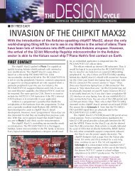
Figure 1 presents the schematic for the DC receiver.<br />
<strong>Direct</strong> conversion receivers function by directly converting<br />
the desired RF signal to an audio frequency. This approach<br />
results in a relatively sensitive receiver that requires a<br />
minimum number of components.<br />
Again referring to Figure 1,<br />
capacitors C1, C2, along with<br />
inductor L1 form a bandpass filter<br />
that transforms the relatively low<br />
50–75 ohm resistance presented<br />
by the antenna up to several<br />
thousand ohms to match the<br />
higher resistance seen at the gate<br />
of Q1. Q1 is a common-source<br />
JFET RF amplifier that provides<br />
up to 30 dB of gain between the<br />
antenna and the transistor’s<br />
drain. The RF amplifier drives a<br />
two-element crystal (Cohn) filter<br />
(X1, X2, C4-C6) with a narrow<br />
bandpass response that is centered<br />
at the desired RF frequency. The<br />
purpose of this filter is to reject undesired signals outside<br />
of the passband in order to avoid overloading the mixer.<br />
Frequency conversion from RF to audio is<br />
accomplished using an SA602 integrated circuit (IC).<br />
Capacitors C10-C11 and the oscillator transistor internal<br />
to the SA602 form a Colpitts crystal local oscillator (LO)<br />
that oscillates at a frequency established by the crystal X3.<br />
Capacitor C12 allows minor adjustment in order to<br />
fine-tune the oscillator frequency. The mixer internal to<br />
the SA602 takes the difference between the RF and LO<br />
signals (which is at audio frequencies) and outputs this to<br />
an LM386 audio amplifier IC configured as a differential<br />
amplifier with 200 Hz–2 kHz bandpass response. The<br />
output of this amplifier is used either to drive a small<br />
headphone or speaker in order to verify operation of the<br />
receiver, or fed to the microphone input of a PC sound<br />
card in order to decode <strong>PSK</strong>-<strong>31</strong>. Variable resistor R4<br />
allows adjustment of the volume of the received signal so<br />
that strong signals do not overload either the ears of the<br />
operator or the sound card of the PC.<br />
This receiver is called a “universal” DC <strong>PSK</strong>-<strong>31</strong><br />
receiver because with an appropriate choice of crystals<br />
X1–X3 and capacitors C1, C2, and C4–C6, it will receive<br />
<strong>PSK</strong>-<strong>31</strong> signals on any of the frequencies listed in Table 1.<br />
Table 1 also lists component values for four frequencies<br />
corresponding to the frequencies where crystals are<br />
Figure 1. <strong>Universal</strong> <strong>PSK</strong> receiver schematic.<br />
2 May 2009 • Bonus Web Feature Copyright © 2009 T & L Publications Inc
Figure 3. Printed circuit board<br />
bottom copper layout.<br />
readily available. <strong>For</strong> other frequencies, the crystal<br />
frequency must be no more than about 0.06% below<br />
the desired <strong>PSK</strong> operating frequency to allow frequency<br />
adjustment using C11.<br />
The inductor specified will work only for constructing<br />
an 80 meter receiver since its adjustment range is just 6%.<br />
In order to construct a receiver that will work on all bands<br />
listed in Table 1 (including 80 m), the inductor must adjust<br />
between 1.75-3.75 µH. An acceptable inductor is<br />
available from www.danssmallpartsandkits.net.<br />
Inexpensive crystals for 80 m are also available from<br />
Digi-Key. A source for suitable crystals for the 15 m, 17 m,<br />
and 20 m bands is www.halted.com. Finally, crystals for<br />
other frequencies can be special<br />
ordered (expensive!) from<br />
International Crystal<br />
(www.icmfg.com).<br />
Construction, Testing,<br />
and Operation<br />
The initial receiver prototype was<br />
constructed and tested by plugging<br />
the components into a proto board.<br />
Once the operation of the circuit was<br />
verified, a printed circuit board (PCB)<br />
was designed using the schematic<br />
capture and layout software provided<br />
by www.expresspcb.com. The board<br />
file can be downloaded from<br />
www.nutsvolts.com.<br />
Figures 2-4 show the top copper<br />
layer, bottom copper layer, and<br />
Figure 2. Printed circuit board<br />
top copper layout.<br />
component layout,<br />
respectively, for the<br />
receiver, while<br />
Figure 4. Printed circuit board<br />
component layout. Note that<br />
C17 is not mounted on the PCB<br />
but rather is connected across<br />
the terminals of J1<br />
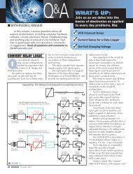
Figure 5 is a photograph of the finished product. In the<br />
PCB version of the receiver, sockets were installed to<br />
allow rapid switching of components C1, C2, C4-C6,<br />
and X1-X3 as necessary for bandswitching.<br />
Once all components are installed, use a multi-meter<br />
to verify that the JFET and ICs power up when the battery<br />
Figure 5. A printed circuit board implementation of the<br />
“universal” <strong>PSK</strong>-<strong>31</strong> receiver. (The battery snap and<br />
antenna connector are not shown in this photo.)<br />
DECODING SOFTWARE<br />
Although installing and using <strong>PSK</strong>-<strong>31</strong> software<br />
on your PC is not the subject of this article, it is not<br />
difficult to get started. There are many free software<br />
applications available for decoding digital signals.<br />
You should spend some time researching to determine<br />
which software package will work best for your<br />
particular combination of computer hardware and<br />
operating experience. Someone with modest experience<br />
installing and using new software should<br />
be able to install the software and learn enough to<br />
use it in an hour or so. Here are a few sites to get<br />
you started:<br />
www.dxzone.com/catalog/Software/<strong>PSK</strong><strong>31</strong>/<br />
www.ac6v.com/software.htm#DIGITAL<br />
www.qsl.net/wm2u/psk<strong>31</strong>.html<br />
http://aintel.bi.ehu.es/psk<strong>31</strong>.html<br />
www.qsl.net/hamscope/<br />
Copyright © 2009 T & L Publications Inc Bonus Web Feature • May 2009 3
Figure 6. Schematic of the signal generator and attenuator<br />
network used for final alignment. Select upper resistance<br />
to produce barely audible output to avoid overloading the<br />
receiver.<br />
5 k50 k<br />
50 <br />
is connected. You should measure approximately five volts<br />
at the drain terminal of Q1 and 1.5 volts at the gate and<br />
source terminals of Q1. If these voltages are not obtained,<br />
verify component values and connections for R1, R2, and<br />
L1 (remember that the inductor is a short at DC!). Next,<br />
verify that you have 8.3 volts at pin 8 of U1, and check<br />
that you have correctly installed D1 if no voltage is<br />
measured there. Finally, verify that you have nine volts<br />
at pin 6 of U2.<br />
A rapid way of aligning the receiver is through the use<br />
of a signal generator and the resistive attenuator shown in<br />
Figure 6. Connect the receiver to the attenuator network,<br />
plug in a headphone or small speaker to the audio jack,<br />
and connect the battery. As you adjust the signal<br />
generator to the desired frequency, you should hear an<br />
audio tone from the speaker that changes in frequency as<br />
you adjust the signal generator. With the signal generator<br />
set to the frequency listed in the table, adjust C12 using<br />
a non-metallic tool until the audio tone decreases in<br />
frequency and then finally vanishes.<br />
If the frequency of the tone won’t<br />
decrease enough, try adding 10-15 pF<br />
of capacitance in parallel with C12 in<br />
order to lower the frequency of the LO.<br />
Also, your crystals will vary slightly in<br />
frequency so try swapping among<br />
To antenna<br />
them. Next, adjust L1 to maximize the<br />
clarity and volume of the received<br />
audio. The final step before decoding<br />
data is to connect the receiver to an<br />
To ground<br />
antenna appropriate for the shortwave<br />
band of interest and listen for the distinctive<br />
warbling of <strong>PSK</strong>-<strong>31</strong> signals when the shortwave<br />
bands are open.<br />
If you don’t have a signal generator available, connect<br />
the receiver to an antenna and then adjust L1 and C12 for<br />
best reception of the <strong>PSK</strong>-<strong>31</strong> tones when the appropriate<br />
band is open.<br />
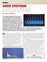
Once your receiver is operating properly and you’ve<br />
installed <strong>PSK</strong>-<strong>31</strong> decoding software on your PC (see<br />
sidebar), the final step is to connect the audio output of<br />
the receiver to the sound card of the PC using an audio<br />
patch cord with 1/8” phone plugs on each end. After you<br />
launch the software, you should be able to see the <strong>PSK</strong><br />
signals on the PC’s display and read the conversation in<br />
the text window. Figure 7 is a screen capture of the<br />
Hamscope software using output from the receiver<br />
shown in Figure 5, configured for the 20 m band.<br />
I hope you have as much fun building and using your<br />
<strong>Universal</strong> <strong>PSK</strong> <strong>Receiver</strong> as I have had with mine! You<br />
may contact me with any questions or comments at<br />
john.post@erau.edu. NV<br />
Figure 7.<br />
Screen capture of<br />
decoded <strong>PSK</strong>-<strong>31</strong><br />
signals produced<br />
by the receiver<br />
shown in Figure 5.<br />
4 May 2009 • Bonus Web Feature Copyright © 2009 T & L Publications Inc
Parts List<br />
Item Description Digi-Key Part No.<br />
Resistors (1/4 Watt, 5%)<br />
R1 750 ohm P750BACT-ND<br />
R2 2.2K P2.2KBACT-ND<br />
R3 47K P47KBACT-ND<br />
R4 5K D4AA53-ND<br />
Capacitors (16 volts or higher)<br />
C1 680 pF ceramic* 490-3664-ND<br />
C2 6,800 pF ceramic* 490-3854-ND<br />
C3, C7, C17 0.047 µF ceramic 490-3842-ND<br />
C4, C5, C6 18 pF ceramic* 490-3632-ND<br />
C8, C9, C16 0.1 µF ceramic 490-3810-ND<br />
C10, C11 47 pF ceramic 490-3657-ND<br />
C12 2.7-10 pF trimmer 490-1971-ND<br />
C13 0.01 µF ceramic 490-3812-ND<br />
C14 100 µF electrolytic P833-ND<br />
C15 10 µF electrolytic P807-ND<br />
Inductors (7MM IF can type)<br />
L1 3.3 µH adjustable*% TK<strong>31</strong>10-ND<br />
Semiconductors<br />
D1 1N914 diode 1N914BCT-ND<br />
Q1 MPF102 JFET MPF1-02-ND<br />
U1 SA 602 AN 568-1201-5-ND<br />
U2 LM386 LM386-1-ND<br />
Miscellaneous<br />
B1 9V battery N145-ND<br />
J1 1/8” phone jack CP-3502MJ-ND<br />
X1, X2, X3 3.579 MHz crystal* X011-ND<br />
Sockets<br />
A461-ND<br />
* Digi-Key part is for 80 meters only. % for all band operation, use a 1.75-3.75 µH<br />
adjustable inductor (search for “4 µH 7MM SINGLE WINDING IF CAN” at<br />
(www.danssmallpartsandkits.net).<br />
A kit containing the printed circuit board, the variable inductor from Dan’s, a phone jack, and<br />
assembly instructions is available for $10. Contact the author at john.post@erau.edu to request<br />
the kit.<br />
Sources<br />
All parts for 80 m receiver<br />
www.digikey.com<br />
Crystals for 20 m, 17 m, and 15 m<br />
www.halted.com<br />
1.75-3.75 µH adjustable inductor<br />
www.danssmallpartsandkits.net<br />
Crystals for additional frequencies<br />
International Crystal (www.icmfg.com)<br />
ExpressPCB file for PCB<br />
www.nutsvolts.com/media-files/psk_receiver.pcb<br />
Datasheets for ICs<br />
www.onsemi.com/pub_link/Collateral<br />
/MPF102-D.PDF<br />
www.datasheetcatalog.com/datasheets_pdf<br />
/S/A/6/0/SA602AN_01.shtml<br />
www.datasheetcatalog.com/datasheets_pdf<br />
/L/M/3/8/LM386.shtml<br />
Copyright © 2009 T & L Publications Inc Bonus Web Feature • May 2009 5