A Universal Direct Conversion Receiver For PSK-31 - Nuts & Volts ...
A Universal Direct Conversion Receiver For PSK-31 - Nuts & Volts ...
A Universal Direct Conversion Receiver For PSK-31 - Nuts & Volts ...

You also want an ePaper? Increase the reach of your titles
YUMPU automatically turns print PDFs into web optimized ePapers that Google loves.
Shortwave<br />
Band (meters) Frequency (kHz) C1 (pF) C2 (pF) C4-C6 (pF)<br />
160 1838.15 3,300 33,000 24 pF<br />
80 3580.15* 680 6,800 18 pF<br />
40 7080.15 150 1,500 18 pF<br />
30 10142.15 150 1,500 10 pF<br />
20 14070.15* 47 470 10 pF<br />
17 18100.15* 43 330 10 pF<br />
15 21080.15* 18 150 10 pF<br />
12 24920.15 18 150 10 pF<br />
10 28120.15 18 150 10 pF<br />
Table 1. Recommended frequencies for <strong>PSK</strong>-<strong>31</strong> activity along with suggested<br />
values for C1, C2, and C4-C6. (*Inexpensive crystals for these bands are available<br />
from Halted Specialties (www.halted.com). <strong>For</strong> the other bands, custom crystals<br />
can be ordered from International Crystal (www.icmfg.com).<br />
example of Morse code so that shorter codes are assigned<br />
to letters of the alphabet that appear more frequently<br />
(like e) and longer codes are assigned for infrequently<br />
used letters (such as z). This minimizes the number of bits<br />
required to transmit a given amount of information and<br />
maximizes the code’s efficiency.<br />
Table 1 lists the frequencies where <strong>PSK</strong>-<strong>31</strong> activities<br />
are concentrated. From my listening experience, the vast<br />
majority of activity takes place on 3.580 and 14.070 MHz<br />
in the 80 and 20 meter shortwave bands. Due to the<br />
limitations of propagation through the ionosphere,<br />
signals on the 80 meter band are strongest late at night —<br />
especially in the winter when nights are longer — while 20<br />
meter propagation is best late during the day, especially<br />
in the summer when days are longer. A quick way of<br />
checking band conditions is to use a shortwave receiver<br />
to listen for the time station WWV or WWVH (which<br />
broadcasts on 2.5, 5.0, 10.0, 15.0, and 20.0 MHz) at<br />
the frequency nearest the one you are interested in.<br />
The <strong>Receiver</strong><br />
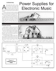
Figure 1 presents the schematic for the DC receiver.<br />
<strong>Direct</strong> conversion receivers function by directly converting<br />
the desired RF signal to an audio frequency. This approach<br />
results in a relatively sensitive receiver that requires a<br />
minimum number of components.<br />
Again referring to Figure 1,<br />
capacitors C1, C2, along with<br />
inductor L1 form a bandpass filter<br />
that transforms the relatively low<br />
50–75 ohm resistance presented<br />
by the antenna up to several<br />
thousand ohms to match the<br />
higher resistance seen at the gate<br />
of Q1. Q1 is a common-source<br />
JFET RF amplifier that provides<br />
up to 30 dB of gain between the<br />
antenna and the transistor’s<br />
drain. The RF amplifier drives a<br />
two-element crystal (Cohn) filter<br />
(X1, X2, C4-C6) with a narrow<br />
bandpass response that is centered<br />
at the desired RF frequency. The<br />
purpose of this filter is to reject undesired signals outside<br />
of the passband in order to avoid overloading the mixer.<br />
Frequency conversion from RF to audio is<br />
accomplished using an SA602 integrated circuit (IC).<br />
Capacitors C10-C11 and the oscillator transistor internal<br />
to the SA602 form a Colpitts crystal local oscillator (LO)<br />
that oscillates at a frequency established by the crystal X3.<br />
Capacitor C12 allows minor adjustment in order to<br />
fine-tune the oscillator frequency. The mixer internal to<br />
the SA602 takes the difference between the RF and LO<br />
signals (which is at audio frequencies) and outputs this to<br />
an LM386 audio amplifier IC configured as a differential<br />
amplifier with 200 Hz–2 kHz bandpass response. The<br />
output of this amplifier is used either to drive a small<br />
headphone or speaker in order to verify operation of the<br />
receiver, or fed to the microphone input of a PC sound<br />
card in order to decode <strong>PSK</strong>-<strong>31</strong>. Variable resistor R4<br />
allows adjustment of the volume of the received signal so<br />
that strong signals do not overload either the ears of the<br />
operator or the sound card of the PC.<br />
This receiver is called a “universal” DC <strong>PSK</strong>-<strong>31</strong><br />
receiver because with an appropriate choice of crystals<br />
X1–X3 and capacitors C1, C2, and C4–C6, it will receive<br />
<strong>PSK</strong>-<strong>31</strong> signals on any of the frequencies listed in Table 1.<br />
Table 1 also lists component values for four frequencies<br />
corresponding to the frequencies where crystals are<br />
Figure 1. <strong>Universal</strong> <strong>PSK</strong> receiver schematic.<br />
2 May 2009 • Bonus Web Feature Copyright © 2009 T & L Publications Inc