A Universal Direct Conversion Receiver For PSK-31 - Nuts & Volts ...
A Universal Direct Conversion Receiver For PSK-31 - Nuts & Volts ...
A Universal Direct Conversion Receiver For PSK-31 - Nuts & Volts ...

You also want an ePaper? Increase the reach of your titles
YUMPU automatically turns print PDFs into web optimized ePapers that Google loves.
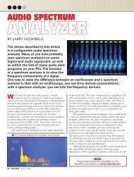
Figure 6. Schematic of the signal generator and attenuator<br />
network used for final alignment. Select upper resistance<br />
to produce barely audible output to avoid overloading the<br />
receiver.<br />
5 k50 k<br />
50 <br />
is connected. You should measure approximately five volts<br />
at the drain terminal of Q1 and 1.5 volts at the gate and<br />
source terminals of Q1. If these voltages are not obtained,<br />
verify component values and connections for R1, R2, and<br />
L1 (remember that the inductor is a short at DC!). Next,<br />
verify that you have 8.3 volts at pin 8 of U1, and check<br />
that you have correctly installed D1 if no voltage is<br />
measured there. Finally, verify that you have nine volts<br />
at pin 6 of U2.<br />
A rapid way of aligning the receiver is through the use<br />
of a signal generator and the resistive attenuator shown in<br />
Figure 6. Connect the receiver to the attenuator network,<br />
plug in a headphone or small speaker to the audio jack,<br />
and connect the battery. As you adjust the signal<br />
generator to the desired frequency, you should hear an<br />
audio tone from the speaker that changes in frequency as<br />
you adjust the signal generator. With the signal generator<br />
set to the frequency listed in the table, adjust C12 using<br />
a non-metallic tool until the audio tone decreases in<br />
frequency and then finally vanishes.<br />
If the frequency of the tone won’t<br />
decrease enough, try adding 10-15 pF<br />
of capacitance in parallel with C12 in<br />
order to lower the frequency of the LO.<br />
Also, your crystals will vary slightly in<br />
frequency so try swapping among<br />
To antenna<br />
them. Next, adjust L1 to maximize the<br />
clarity and volume of the received<br />
audio. The final step before decoding<br />
data is to connect the receiver to an<br />
To ground<br />
antenna appropriate for the shortwave<br />
band of interest and listen for the distinctive<br />
warbling of <strong>PSK</strong>-<strong>31</strong> signals when the shortwave<br />
bands are open.<br />
If you don’t have a signal generator available, connect<br />
the receiver to an antenna and then adjust L1 and C12 for<br />
best reception of the <strong>PSK</strong>-<strong>31</strong> tones when the appropriate<br />
band is open.<br />
Once your receiver is operating properly and you’ve<br />
installed <strong>PSK</strong>-<strong>31</strong> decoding software on your PC (see<br />
sidebar), the final step is to connect the audio output of<br />
the receiver to the sound card of the PC using an audio<br />
patch cord with 1/8” phone plugs on each end. After you<br />
launch the software, you should be able to see the <strong>PSK</strong><br />
signals on the PC’s display and read the conversation in<br />
the text window. Figure 7 is a screen capture of the<br />
Hamscope software using output from the receiver<br />
shown in Figure 5, configured for the 20 m band.<br />
I hope you have as much fun building and using your<br />
<strong>Universal</strong> <strong>PSK</strong> <strong>Receiver</strong> as I have had with mine! You<br />
may contact me with any questions or comments at<br />
john.post@erau.edu. NV<br />
Figure 7.<br />
Screen capture of<br />
decoded <strong>PSK</strong>-<strong>31</strong><br />
signals produced<br />
by the receiver<br />
shown in Figure 5.<br />
4 May 2009 • Bonus Web Feature Copyright © 2009 T & L Publications Inc