
Create successful ePaper yourself
Turn your PDF publications into a flip-book with our unique Google optimized e-Paper software.
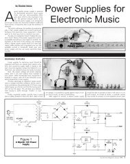
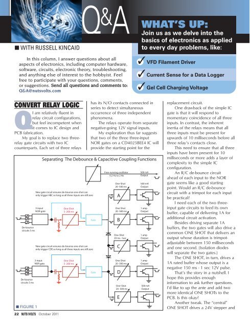
■ WITH RUSSELL KINCAIDQ & AIn this column, I answer questions about allaspects of electronics, including computer hardware,software, circuits, electronic theory, troubleshooting,and anything else of interest to the hobbyist. Feelfree to participate with your questions, comments,or suggestions. Send all questions and comments to:Q&A@nutsvolts.comWHAT’S UP:Join us as we delve into thebasics of electronics as appliedto every day problems, like:✓● VFD Filament Driver●✓Current Sense for a Data Logger●✓Gel Cell Charging VoltageCONVERT RELAY LOGICQI am relatively fluent inrelay circuit configurations,but feel incompetent whenit comes to IC design andPCB fabrication.My goal is to replace two threerelaygate circuits with two ICcounterparts. Each set of three relaysDe-bouncecircuits 5 msDe-bouncecircuits 5 ms■ FIGURE 13-inputNOR gate3-inputNOR gate22 October 2011has its N/O contacts connected inseries to detect simultaneousoccurrence of three independentphenomena.The relays operate from separatenegative-going 12V signal inputs.My exploration thus far suggeststhat two of the three three-inputNOR gates on a CD4025BEE4 IC willprovide the starting point for theSeparating The Debounce & Capacitive Coupling FunctionsNew gate circuit ensures de-bounce one-shot canonly trigger ABC so long as all three inputs are still zeroOne-Shot5 -200 msOne-Shot5 -200 msGateNew gate circuit ensures de-bounce one-shot canonly trigger CDE so long as all three inputs are still zeroGateFree-running oscillator0.2 Hz to 2 HzOne-Shot20 -500 msAOne-Shot20 -500 msBOne-Shot20 ms -1secCOne-Shot20 -500 msDOne-Shot20 -500 msE500 mAOutput500 mAOutput1 ampOutput1 ampOutput1 ampOutput500 mAOutputreplacement circuit.One drawback of the simple ICgate is that it will respond tomomentary coincidence of all threeinputs. In contrast, the inherentinertia of the relays means that allthree inputs must be present forupwards of 10 milliseconds before allthree relay’s contacts close.This need to ensure that all threeinputs have been present for 10milliseconds or more adds a layer ofcomplexity to the simple ICconfiguration.An R/C de-bounce circuitahead of each input to the NORgate seems like a good startingpoint. Would an R/C de-bouncecircuit with a trimpot for each inputbe practical?I need each of the two threeinputgate circuits to feed its ownbuffer, capable of delivering 1A foradditional circuit activation.Besides driving separate 1Abuffers, the two gates will also drive acommon ONE SHOT that delivers anoutput whose duration is trimpotadjustablebetween 150 millisecondsand one second. (Isolation diodeswill separate the two gates.)The ONE SHOT, in turn, drives a1A rated buffer whose output is anegative 150 ms - 1 sec 12V pulse.That’s the story in a nutshell. Ihope this provides enoughinformation to ask further questions.I’d like to up the ante and add twomore identical ONE SHOTs to thePCB. Is this okay?Another tweak. The “central”ONE SHOT drives a 24V stepper and
QUESTIONS & ANSWERSmax, the magnetizing current at theinput should be no more than 30mA. I will try 10 mA which meansthe inductive reactance will be5V/.01 = 500 ohms. Since thefrequency is 50 kHz, the inductancehas to be L = Xl/2/PI/F = 1.59 mH.Calculating the turns from N =(L*1e6/Al)^.5, then N = .74. That’snot reasonable. I can use more turns.Twenty turns will fit in one layer onthe bobbin, so use 10 turns to thecenter-tap, then L = 230 mH. Now,check to see if the core is bigenough: WaAc for the core is givenas .162. WaAc is the product of thecore cross-section and the windowarea. The equation is:whereWaAc = k*Po*10^8/B/Fk = .00528 for an EcorePo = 5V*0.3A = 1.5 wattB = 1000 gaussF = 50KHzThen:WaAc = .0016 and the core ismuch larger than needed.The wire size can be calculatedfrom: AWG = -4.31*ln(1.889*I/Cd),where Cd is the current density inamperes per square centimeter. TheMicrometals manual recommends400 A/sq cm.That yields an AWG of #28;anything bigger is okay.CURRENT SENSE FORA DATA LOGGERQI have a DATAQ EL-USB-5data logger. I wantto use it to track ■ FIGURE 5when 110Vappliances turn on and off;for instance, a refrigerator’scompressor. I wish to use aleg of an extension cord tosense current flow.The data logger can beset to be triggered by acontact closure or to apre-set voltage (three voltsmin). Can you design acircuit that can provide asatisfactory voltagetrigger (using a 9V battery)from a current sensor(toroid)? The sensorwould have to beadjustable such that thecurrent draw from thecontrol circuit of theappliance will not interferewith the sensing of thecompressor’s current draw.— Charlie YoungAI measured the currentdraw of my small freezer tobe four amps; if you use a1,000:1 transformer, theoutput current will be 4 mA; 4 mA *1K = 4V which is enough to triggerthe data logger. Current transformersdon’t work well when the load isgreater than 100 ohms, so I am usingthe input impedance of an op-amp(essentially zero ohms); see Figure 4.I am rectifying the output because Isuspect that the data logger prefersDC input. The gain pot can be 2K or10K, depending on the current rangeyou expect to encounter.Mouser part number 553-CST-1020 is rated at 20 amps and costs$6.11.GEL CELLCHARGING VOLTAGEQI have a 12V flashlight witha 12V 7AH gel battery. Ineed to replace the internalcharging circuit. I will beusing an external 12V DC supply.What would be therecommended charging voltage■ FIGURE 4for this type of battery?— Ken BartoneAA lead-acid type battery isfully charged at 13.8 VDC.A 10 hour charge isrecommended so thecharging current should be 0.7amps. You should measure theoutput voltage of your power supplybecause it may be high enough tocharge the battery without anyadditional circuitry. My RadioShackpower supply output is 14V no loadwhich is adequate; I would put twoor three ohms in series to limit thecurrent. If the power supply voltage isgreater than 15V, you will not beable to leave the battery connectedfor more than 10 hours or it willovercharge (the GEL cell has someovercharge protection, but don’tdepend on it). Another solutionwould be to plug it into the cigarettelighter socket in the car. The voltageis 13.8 VDC when the motor isrunning.A boost circuit is needed to get13.8V from a 12V source; I usedNational Semiconductor’s WebBench(www.national.com/en/webench/October 2011 25
SEPIC PARTS LIST■ FIGURE 6PART DESCRIPTION PKG PART # PRICEC1 100 µF, 25V, ALUM 6.3MM 647-UPW1E101MED 0.28C2 0.1 µF, 50V, CERAMIC 5X3.5MM 81-RPER71H104K2P1A03 0.18C3 2.2 nF, 50V, CERAMIC 5X3.5MM 81-RPER71222K2P1A03B 0.24C4 .033 µF, 50V, CERAMIC 5X3.5MM 81-RPER71333K2P1A03B 0.23C5 1 nF, 50V, CERAMIC 5X3.5MM 81-RPER71102K2P1A03B 0.24C6, C7 1000 µF, 35V, ALUM 12.5x5MM 871-B41044A7108M000 0.54L1 27 µH, 6.4A TOROID .86DIA 542-2100HT-270H-RC 2.61L2 100 µH, 4.6A TOROID .86DIA 542-2100HT-101H-RC 2.61D1 3A, 100V SHOTTKEY AXIAL 844-31DQ10 1.06R4 0.05 OHM, 5%, 1W TO-220 652-PWR221T-30-R050J 2.60ALL OTHER RESISTORS 1/8W, 1%IC1 LM3488 CUR. MODE MSOP-8 LM3488QMMTR-ND 3.66power.html) to design the circuit ofFigure 5. National’s design used allsurface-mount parts but I have listedthrough hole parts in the parts list(except for the LM3488 which is onlyavailable as surface-mount). The partnumbers in the parts list (Figure 6)are Mouser except the LM3488 isfrom Digi-Key. The LM3488 is alsoavailable at Newark.This is a SEPIC design whichmeans that the output can behigher or lower than the input. Theoperating frequency is around500 kHz, so a good layout isnecessary. The LM3488 is a currentmode device because the inductorcurrent is sensed by R4 and fed topin 1 which will shuts off Q1when the sensed voltage is 0.156.When Q1 shuts off, the energystored in L1 is transferred to theoutput through C6 and D1. L2provides a DC path to ground.Otherwise, C6 would keep chargingto higher voltage.Voltage regulation is obtained byfeeding part of the output voltageback to pin 3 which has a thresholdof 1.26V. National estimates theefficiency to be 88% but theysacrificed some efficiency for size sothis design should be better. NV26 October 2011