Build Your Own Midi to Synthesizer Interface - Nuts & Volts Magazine
Build Your Own Midi to Synthesizer Interface - Nuts & Volts Magazine
Build Your Own Midi to Synthesizer Interface - Nuts & Volts Magazine

Create successful ePaper yourself
Turn your PDF publications into a flip-book with our unique Google optimized e-Paper software.
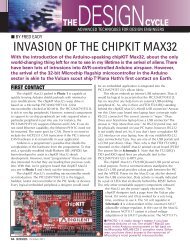
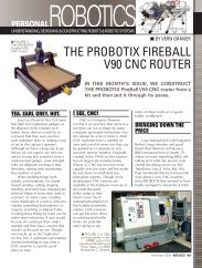
Figure 6 — Front Panel<br />
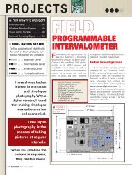
Figure 7 — Front Panel Drilling Guide<br />
along with their associated<br />
resis<strong>to</strong>rs, translate the<br />
TTL control signals from<br />
the 68705 <strong>to</strong> a suitable<br />
+15V level.<br />
To wrap things up,<br />
notice that there have<br />
been numerous capaci<strong>to</strong>rs<br />
not mentioned in<br />
the circuit description so<br />
far. Most of these are<br />
decoupling, bypass, or<br />
compensation caps. In<br />
general, these caps are<br />
used <strong>to</strong> stabilize the<br />
operation of the various<br />
chips. Even though they<br />
don’t seem <strong>to</strong> do anything<br />
very glamorous, all<br />
of them are essential for<br />
proper performance.<br />
Well, you’re probably<br />
sick of circuit descriptions,<br />
so let’s move on<br />
now and see how <strong>to</strong><br />
actually construct the<br />
MTS-100!<br />
BUILD IT!<br />
Besides the hardware<br />
just described, it<br />
also takes firmware <strong>to</strong> put the MTS-<br />
100 through its paces. If you’d like <strong>to</strong><br />
try a complete homebrew approach,<br />
then first obtain a blank 68705 chip.<br />
Jameco Electronics (1355 Shoreway<br />
Road, Belmont, CA 94002) is a good<br />
source for the part, and has them for<br />
under $15.00.<br />
Next, you’ll need <strong>to</strong> get your<br />
hands on the program for the<br />
firmware. Even though the object<br />
code is quite short (about 700 bytes),<br />
it’s still <strong>to</strong>o long <strong>to</strong> appear in this article.<br />
However, the complete annotated<br />
assembler source code is available free<br />
of charge for download on the World<br />
Wide Web. See the Parts List for<br />
details.<br />
Next, you’ll need <strong>to</strong> assemble the<br />
code and burn it in<strong>to</strong> your chip. There<br />
are dozens of excellent freeware and<br />
shareware cross-assemblers available<br />
on the Internet; try your favorite<br />
search engine and see! As for programming<br />
the microprocessor, get<br />
your hands on a 68705 Mo<strong>to</strong>rola<br />
manual. You’ll find complete directions<br />
for programming the internal<br />
EPROM.<br />
But if the thought of hassling<br />
around with software doesn’t appeal<br />
<strong>to</strong> you, then you might want <strong>to</strong> consider<br />
purchasing the kit of parts which<br />
includes a programmed 68705. Refer<br />
<strong>to</strong> the Parts List for ordering information.<br />
All of the other components in<br />
the MTS-100 are available from a variety<br />
of sources. A quick check of the<br />
ads in this magazine or the catalogs<br />
of some of the better mail order houses<br />
will fill in the gaps almost immediately.<br />
After gathering the parts <strong>to</strong>gether,<br />
ponder what method of construction<br />
you will employ. Most of the project<br />
is non-critical, but keep in mind<br />
that the S/H circuits, as well as the<br />
crystal oscilla<strong>to</strong>r, demand neatness.<br />
(Stray capacitance and the like can<br />
wreak havoc.) So, if you decide <strong>to</strong><br />
handwire it, be sure you keep everything<br />
nice and tidy.<br />
The best approach by far, however,<br />
is <strong>to</strong> use a printed circuit board.<br />
This is much more fun <strong>to</strong> put <strong>to</strong>gether,<br />
looks pretty, and will probably minimize<br />
any potential wiring errors. Many<br />
hobbyists are becoming old hands at<br />
etching their own boards nowadays<br />
using a laser printer and iron-on transfer<br />
material. If you’d like <strong>to</strong> give it<br />
whirl, refer <strong>to</strong> Figure 4 which shows<br />
the 1:1 positive artwork for the foil<br />
side. Conveniently, it all fits on a 4” by<br />
6” board, which is a standard copper<br />
clad size.<br />
See Figure 5 for the<br />
parts placement guide.<br />
Loading the board is pretty<br />
straightforward as long<br />
as you obey the usual<br />
rules. For example, be<br />
sure <strong>to</strong> observe the orientations<br />
of all of the polarized<br />
components. Diode<br />
D1 is marked with a standard<br />
schematic symbol. A<br />
plus sign indicates the<br />
positive lead of electrolytic<br />
capaci<strong>to</strong>rs C14-C18. The<br />
emitter, base, and collec<strong>to</strong>r<br />
leads of Q1-Q4 are<br />
called out with their initial<br />
letters.<br />
Finally, don’t forget <strong>to</strong><br />
install the 15 jumpers.<br />
Figure 8 These are indicated as<br />
straight lines connecting<br />
pairs of points on the diagram.<br />
After loading the<br />
printed circuit board, you<br />
can then proceed <strong>to</strong> the<br />
final wiring of the front<br />
panel. A rack-mounted<br />
unit is perhaps best, since<br />
most pro equipment<br />
comes that way nowadays.<br />
The MTS-100 fits nicely behind a<br />
standard 1U rack panel (1-3/4” by<br />
19”). Figure 6 shows a sample design,<br />
while Figure 7 gives the related drilling<br />
guide. The circuit board mounts<br />
behind the panel on standoffs or little<br />
angles, using #4 hardware <strong>to</strong> secure<br />
things.<br />
To connect the circuit board <strong>to</strong><br />
the panel, notice that all of the relevant<br />
pads are labeled on the parts<br />
placement guide in Figure 5. Even so,<br />
here are a few additional tips. For best<br />
results, twisted triples should be used<br />
<strong>to</strong> connect up jacks J5-J7. The<br />
schematic in Figure 2 shows the pin<br />
arrangement of these jacks, as seen<br />
from the solder lug side. Notice that<br />
G, the ground wire of the triple going<br />
<strong>to</strong> the MIDI input, does not connect<br />
<strong>to</strong> J5. Clip if off, and let it float.<br />
The MTS-100 can<br />
easily interface a<br />
MIDI instrument —<br />
such as a music keyboard<br />
or a computer<br />
running sequencer<br />
software — with<br />
most any analog<br />
synthesizer.<br />
<strong>Nuts</strong> & <strong>Volts</strong> <strong>Magazine</strong>/December 1997 55