2800/3350 Air Cart Manual - Amity Technology
2800/3350 Air Cart Manual - Amity Technology
2800/3350 Air Cart Manual - Amity Technology

Create successful ePaper yourself
Turn your PDF publications into a flip-book with our unique Google optimized e-Paper software.
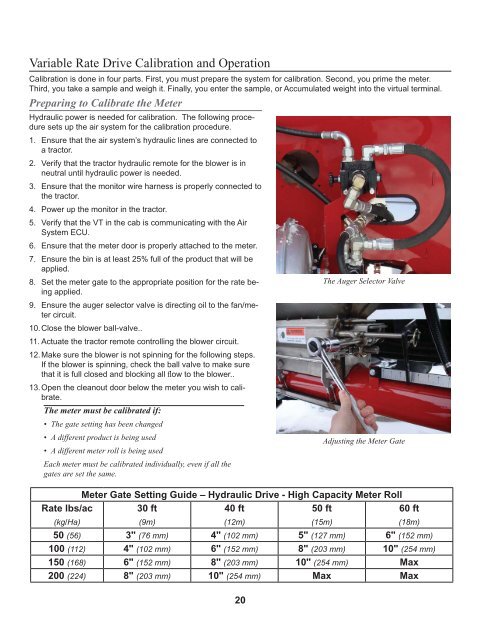
Variable Rate Drive Calibration and Operation<br />
Calibration is done in four parts. First, you must prepare the system for calibration. Second, you prime the meter.<br />
Third, you take a sample and weigh it. Finally, you enter the sample, or Accumulated weight into the virtual terminal.<br />
Preparing to Calibrate the Meter<br />
Hydraulic power is needed for calibration. The following procedure<br />
sets up the air system for the calibration procedure.<br />
1. Ensure that the air system’s hydraulic lines are connected to<br />
a tractor.<br />
2. Verify that the tractor hydraulic remote for the blower is in<br />
neutral until hydraulic power is needed.<br />
3. Ensure that the monitor wire harness is properly connected to<br />
the tractor.<br />
4. Power up the monitor in the tractor.<br />
5. Verify that the VT in the cab is communicating with the <strong>Air</strong><br />
System ECU.<br />
6. Ensure that the meter door is properly attached to the meter.<br />
7. Ensure the bin is at least 25% full of the product that will be<br />
applied.<br />
8. Set the meter gate to the appropriate position for the rate being<br />
applied.<br />
9. Ensure the auger selector valve is directing oil to the fan/meter<br />
circuit.<br />
10. Close the blower ball-valve..<br />
11. Actuate the tractor remote controlling the blower circuit.<br />
12. Make sure the blower is not spinning for the following steps.<br />
If the blower is spinning, check the ball valve to make sure<br />
that it is full closed and blocking all fl ow to the blower..<br />
13. Open the cleanout door below the meter you wish to calibrate.<br />
The meter must be calibrated if:<br />
• The gate setting has been changed<br />
• A different product is being used<br />
• A different meter roll is being used<br />
Each meter must be calibrated individually, even if all the<br />
gates are set the same.<br />
20<br />
The Auger Selector Valve<br />
Adjusting the Meter Gate<br />
Meter Gate Setting Guide – Hydraulic Drive - High Capacity Meter Roll<br />
Rate lbs/ac<br />
(kg/Ha)<br />
30 ft<br />
(9m)<br />
40 ft<br />
(12m)<br />
50 ft<br />
(15m)<br />
60 ft<br />
(18m)<br />
50 (56) 3" (76 mm) 4" (102 mm) 5" (127 mm) 6" (152 mm)<br />
100 (112) 4" (102 mm) 6" (152 mm) 8" (203 mm) 10" (254 mm)<br />
150 (168) 6" (152 mm) 8" (203 mm) 10" (254 mm) Max<br />
200 (224) 8" (203 mm) 10" (254 mm) Max Max