198934 Roof Stairs INSTALLATION INSTRUCTIONS.pdf - Westeel
198934 Roof Stairs INSTALLATION INSTRUCTIONS.pdf - Westeel
198934 Roof Stairs INSTALLATION INSTRUCTIONS.pdf - Westeel

Create successful ePaper yourself
Turn your PDF publications into a flip-book with our unique Google optimized e-Paper software.
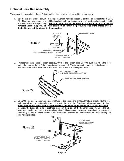
Optional Peak Rail Assembly<br />
The peak rail is an option to the roof stairs and is intended to be assembled to the roof stairs.<br />
1. Bolt the two extensions (234068) to the upper vertical handrail support C-sections on the roof stair (fIGURE<br />
21). Note that these supports should be installed such that the center web of the C-section is on the inside<br />
of the bin (towards the peak ring). The tops of the peak rail extensions protrude about 8 ½” above the<br />
vertical handrail supports. They are bolted on, such that the protruding legs of the angles are on<br />
the inside and pointing towards the peak ring.<br />
EXTENSION<br />
FLANGES<br />
ON INSIDE<br />
EXTENSION (234068)<br />
Figure 21<br />
PEAK<br />
RING<br />
TOP VIEW<br />
CENTER WEB OF HANDRAIL<br />
SUPPORT FACING TOWARDS PEAK RING<br />
VERTICAL HANDRAIL<br />
SUPPORT C-SECTION<br />
2. Preassemble the peak rail support posts (234092) to the support clips (234093) such that when the clips<br />
match the slope of the roof, the support posts are vertical. The flange on the support posts should be<br />
oriented such that the peak rails are attached on the inside of the support posts.<br />
SUPPORT POST FLANGES<br />
ON INSIDE (TOWARDS PEAK RING)<br />
SUPPORT POSTS ARE VERTICAL<br />
Figure 22<br />
3. Using U bolts, loosely secure one peak rail tube to the extensions (234068) that are attached to the roof<br />
stair handrail support posts and the second tube to the mid-point of the handrail support posts. At the<br />
upper location the tubes should butt up against the flange of the extensions. At the mid-point<br />
location, the tubes should not protrude inside of the plane of the handrail support. Once the tubes<br />
have been leveled (as per the following instructions) it is necessary to secure the ends of the tubes using<br />
self-drilling screws at the two locations referred to here. Drill in from the outside of the tubes, through the<br />
pilot holes provided.<br />
Figure 23<br />
BUTT TUBE ENDS<br />
AGAINST EXTENSIONS<br />
BEFORE SECURING<br />
LOWER TUBES SHOULD<br />
NOT PROTRUDE INSIDE<br />
OF SUPPORT POSTS<br />
Page 25