Installation and Operating Manual System Protection Relay Energy ...
Installation and Operating Manual System Protection Relay Energy ...
Installation and Operating Manual System Protection Relay Energy ...

Create successful ePaper yourself
Turn your PDF publications into a flip-book with our unique Google optimized e-Paper software.
Testing <strong>Relay</strong> 1<br />
Now you are ready to test the relay<br />
contact function. This example assumes<br />
a nominal 120V product.<br />
With no measuring signal input, the relay<br />
should be tripped (no Voltage ). Confirm<br />
that <strong>Relay</strong> 1 contact is de-energised.<br />
Apply a three-phase, variable, AC voltage<br />
source to the input, initially set to 120V.<br />
Now decrease the voltage slowly.<br />
Confirm <strong>Relay</strong> 1 contact is energised.<br />
Note that the SPR is checking each phase<br />
for a voltage less than 100 V.<br />
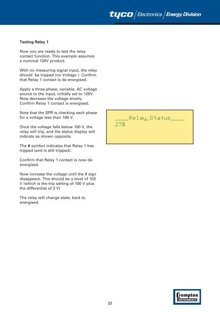
Once the voltage falls below 100 V, the<br />
relay will trip, <strong>and</strong> the status display will<br />
indicate as shown opposite.<br />
The # symbol indicates that <strong>Relay</strong> 1 has<br />
tripped (<strong>and</strong> is still tripped).<br />
Confirm that <strong>Relay</strong> 1 contact is now deenergised.<br />
Now increase the voltage until the # sign<br />
disappears. This should be a level of 103<br />
V (which is the trip setting of 100 V plus<br />
the differential of 3 V)<br />
The relay will change state, back to<br />
energised.<br />
33