

1756-RM093F-EN-P, GuardLogix Controller Systems ... - Tuv-fs.com
1756-RM093F-EN-P, GuardLogix Controller Systems ... - Tuv-fs.com
1756-RM093F-EN-P, GuardLogix Controller Systems ... - Tuv-fs.com

You also want an ePaper? Increase the reach of your titles
YUMPU automatically turns print PDFs into web optimized ePapers that Google loves.
Appendix C<br />
Reaction Times<br />
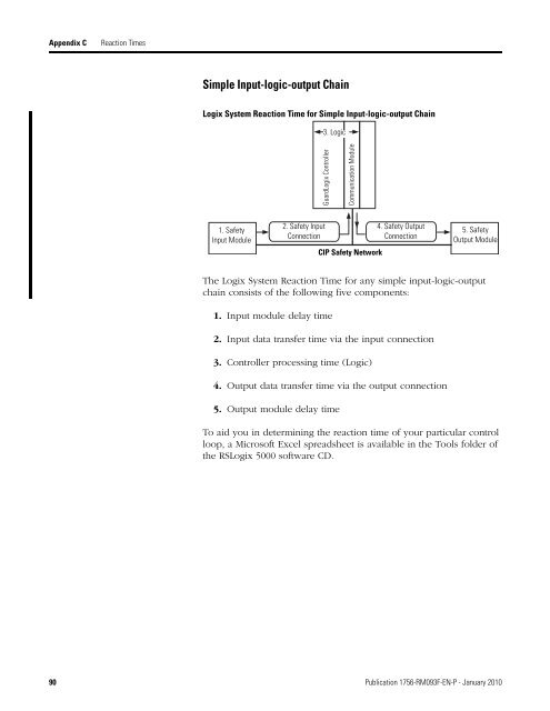
Simple Input-logic-output Chain<br />
Logix System Reaction Time for Simple Input-logic-output Chain<br />
3. Logic<br />
<strong>GuardLogix</strong> <strong>Controller</strong><br />
Communication Module<br />
1. Safety<br />
Input Module<br />
2. Safety Input<br />
Connection<br />
CIP Safety Network<br />
4. Safety Output<br />
Connection<br />
5. Safety<br />
Output Module<br />
The Logix System Reaction Time for any simple input-logic-output<br />
chain consists of the following five <strong>com</strong>ponents:<br />
1. Input module delay time<br />
2. Input data transfer time via the input connection<br />
3. <strong>Controller</strong> processing time (Logic)<br />
4. Output data transfer time via the output connection<br />
5. Output module delay time<br />
To aid you in determining the reaction time of your particular control<br />
loop, a Microsoft Excel spreadsheet is available in the Tools folder of<br />
the RSLogix 5000 software CD.<br />
90 Publication <strong>1756</strong>-<strong>RM093F</strong>-<strong>EN</strong>-P - January 2010


