INTELLIGENT FIRE ALARM CONTROL PANELS MR ... - Secutron
INTELLIGENT FIRE ALARM CONTROL PANELS MR ... - Secutron
INTELLIGENT FIRE ALARM CONTROL PANELS MR ... - Secutron

You also want an ePaper? Increase the reach of your titles
YUMPU automatically turns print PDFs into web optimized ePapers that Google loves.
<strong>INTELLIGENT</strong><br />
<strong>FIRE</strong> <strong>ALARM</strong> <strong>CONTROL</strong> <strong>PANELS</strong><br />
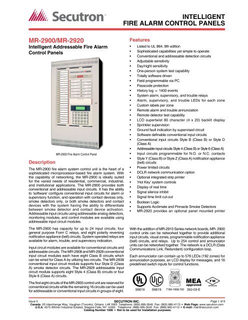
<strong>MR</strong>-2900/<strong>MR</strong>-2920<br />
Intelligent Addressable Fire Alarm<br />
Control Panels<br />
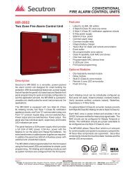
Description<br />
<strong>MR</strong>-2900 Fire Alarm Control Panel<br />
The <strong>MR</strong>-2900 fire alarm system control unit is the heart of a<br />
sophisticated microprocessor-based fire alarm system. With<br />
the capability of networking, the <strong>MR</strong>-2900 is ideally suited<br />
for the varied needs of residential, commercial, industrial,<br />
and institutional applications. The <strong>MR</strong>-2900 provides both<br />
conventional and addressable input circuits. It has the ability<br />
to ‘software’ configure conventional input circuits for alarm or<br />
supervisory function, and operation with contact devices only,<br />
smoke detectors only, or both smoke detectors and contact<br />
devices with the system having the ability to differentiate<br />
between smoke detector and contact device activation.<br />
Addressable input circuits using addressable analog detectors,<br />
monitoring modules, and control modules are available using<br />
addressable input circuit modules.<br />
The <strong>MR</strong>-2900 has capacity for up to 24 input circuits, four<br />
general purpose Form C relays, and eight polarity reversing<br />
notification appliance (bell) circuits. System operated relays are<br />
available for alarm, trouble, and supervisory indication.<br />
Input circuit modules are available for conventional circuits and<br />
addressable circuits. The <strong>MR</strong>-2908 and <strong>MR</strong>-2928 conventional<br />
input circuit modules each have eight Class B circuits which<br />
can be wired for Class A by utilizing two circuits. The <strong>MR</strong>-2938<br />
conventional input circuit module supports four Style D (Class<br />
A) smoke detector circuits. The <strong>MR</strong>-2929 addressable input<br />
circuit module supports eight Style 4 (Class B) circuits or four<br />
Style 6 (Class A) circuits.<br />
The first eight circuits of the <strong>MR</strong>-2900 control unit are reserved for<br />
conventional circuits while the remaining 16 circuits can be used<br />
for addressable or conventional input circuits in groups of eight.<br />
Features<br />
• Listed to UL 864, 9th edition<br />
• Sophisticated capabilities yet simple to operate<br />
• Conventional and addressable detection circuits<br />
• Adjustable sensitivity<br />
• Day/night sensitivity<br />
• One-person system test capability<br />
• Totally software driven<br />
• Field programmable via PC<br />
• Passcode protection<br />
• History log ≈ 1400 events<br />
• System alarm, supervisory, and trouble relays<br />
• Alarm, supervisory, and trouble LEDs for each zone<br />
• Custom labels per zone<br />
• Remote alarm and trouble annunciation<br />
• Remote detector test capability<br />
• LCD supertwist 80 character (4 x 20) backlit display<br />
• Sprinkler supervision<br />
• Ground fault indication by supervised circuit<br />
• Software definable conventional input circuits<br />
• Conventional input circuits Style B (Class B) or Style D<br />
(Class A)<br />
• Addressable input circuits Style 4 (Class B) or Style 6 (Class A)<br />
• Input circuits programmable for N.O. or N.C. contacts<br />
• Style Y (Class B) or Style Z (Class A) notification appliance<br />
(bell) circuits<br />
• Power limited circuits<br />
• DCLR network communication option<br />
• Optional integrated strip printer<br />
• ‘Hot Key’ system controls<br />
• Display of real time<br />
• Signal silence inhibit<br />
• Signal time limit cut-out<br />
• Boolean Logic<br />
• Supports Acclimate and Pinnacle Smoke Detectors<br />
• <strong>MR</strong>-2920 provides an optional panel mounted printer<br />
With the addition of <strong>MR</strong>-2910 Series network boards, <strong>MR</strong>- 2900<br />
control units can be networked together to provide additional<br />
input circuits, visual zones, programmable notification appliance<br />
(bell) circuits, and relays. Up to 254 control and annunciator<br />
units can be networked together. The network is a DCLR (Data<br />
Communications Link, Redundant) configuration loop.<br />
Each annunciator can contain up to 576 LEDs (192 zones) for<br />
annunciation purposes, an LCD display for messages, and 16<br />
predefined switch inputs for control functions.<br />
S6619<br />
S6619<br />
7165-1656:100<br />
MEA<br />
approved<br />
352-03-E<br />
APPROVED<br />
Issue 5 SECUTRON INC.<br />
Page 1 of 8<br />
Canada 25 Interchange Way, Vaughan (Toronto), Ontario L4K 5W3 Telephone: (905) 695-3545 Fax: (905) 660-4113 • Web Page: www.secutron.com<br />
U.S.A. 4575 Witmer Industrial Estates, Niagara Falls, NY 14305 Telephone: (888) 695-3545 Fax: (888) 660-4113 • E-mail: mail@secutron.com<br />
Catalog Number 1006 • Not to be used for installation purposes.
ENTER<br />
SCROLL BYPASS<br />
CLEAR<br />
HOME<br />
Main Control Unit<br />
The system controls<br />
and visual indicators are<br />
contained on the main<br />
circuit board, which also<br />
contains the system<br />
processor, programming<br />
port, printer port and nonvolatile<br />
memory for storage<br />
of system programming.<br />
Operating software is<br />
installed on the main<br />
board for purposes such<br />
as function relay operation,<br />
zone LED annunciation, and<br />
custom zone and devices<br />
messages.<br />
SUPERVISORY<br />
System controls consist of<br />
Fire Drill<br />
Acknowledge<br />
12 system switches (‘Hot<br />
Signal<br />
Keys’) and a 20 position<br />
Lamp Test<br />
Silence<br />
alphanumeric keypad. The 12<br />
Releaser<br />
System<br />
Disconnect<br />
Reset<br />
system switches are factory<br />
Relay<br />
Municipal<br />
and user defined for operations<br />
Disconnect<br />
Disconnect<br />
such as alarm acknowledge,<br />
General<br />
Test Mode<br />
Alarm<br />
notification appliance (bell)<br />
Signal<br />
2nd Stage<br />
Disconnect<br />
Inhibit<br />
silence, and system reset.<br />
The 20 position keypad is<br />
Hot Keys<br />
used for technical functions,system/detector maintenance,<br />
history recall, device and circuit disarming, and for manual<br />
operation of addressable output modules, relay modules,<br />
and notification appliance (bell) circuits.<br />
<strong>ALARM</strong><br />
SUPERVISORY<br />
<strong>ALARM</strong><br />
TROUBLE<br />
1 2 3<br />
4 5 6<br />
7 8 9<br />
. 0<br />
Main Control Unit<br />
Display<br />
The visual display consists of a series of LEDs for common<br />
system indication of power, alarm, supervisory, and trouble.<br />
An LED clock display is provided to display real time. The<br />
flashing colon of the clock provides visual indication of system<br />
processor operation.<br />
AC POWER<br />
C<br />
E<br />
TROUBLE<br />
AC POWER<br />
D<br />
F<br />
The trouble LEDs will indicate both open circuit<br />
and ground fault. The LCD display is used to<br />
determine the exact nature of the trouble.<br />
Addressable input circuits can be configured to<br />
map individual detectors or groups of detectors<br />
to turn-on specific zone indicating lamps.<br />
Addressable devices are also indicated on the<br />
LCD display, which provides device number,<br />
addressable input circuit number, and a custom<br />
message.<br />
Input Circuits<br />
The <strong>MR</strong>-2900 motherboard uses up to three<br />
input circuit modules. Each input circuit module<br />
supports either eight Class B or four Class A<br />
circuits. Three versions are available, models<br />
<strong>MR</strong>-2928 and <strong>MR</strong>-2938 for conventional devices and model<br />
<strong>MR</strong>-2929 for addressable devices. The location for the first<br />
input module will accommodate only a conventional input<br />
circuit module. The remaining two locations can be used for<br />
conventional or addressable input modules.<br />
Conventional circuits are individually software definable for<br />
contact devices only, smoke detectors only, or combination<br />
of smoke detectors and contact devices. Circuits defined for<br />
smoke detector and contact devices are able to differentiate<br />
between smoke detector operation and contact device<br />
operation, which permits<br />
combining contacts<br />
and smoke detectors<br />
on one common circuit.<br />
The circuits are further<br />
definable for alarm or<br />
supervisory. Alarm and<br />
supervisory operation<br />
provides visual indication<br />
on separate LEDs. Input<br />
circuits programmed<br />
for contact devices can<br />
be further defined for<br />
use with N.O. or N.C.<br />
contacts.<br />
CIRCUITS<br />
1 TO 8<br />
CONVENTIONAL<br />
ONLY<br />
1<br />
2<br />
3<br />
4<br />
5<br />
6<br />
7<br />
8<br />
9<br />
10<br />
11<br />
12<br />
13<br />
14<br />
15<br />
16<br />
17<br />
18<br />
19<br />
20<br />
21<br />
22<br />
23<br />
24<br />
CLASS "B" "<br />
CLASS "A"<br />
NOTE : CLASS "A" CIRCUIT<br />
REQUIRES TWO ZONES<br />
<strong>ALARM</strong><br />
SUPER-<br />
VISORY<br />
TROUBLE<br />
LED Zone<br />
Display<br />
END OF LINE<br />
DEVICE<br />
ADDRESSABLE CIRCUIT<br />
T-TAPS ALLOWED ON CLASS "B" WIRING ONLY<br />
System Display<br />
An 80 character supertwist LCD<br />
alphanumeric display is provided<br />
for display of device addresses and<br />
identification, zone identification<br />
for conventional input circuits, and<br />
for display of history files, first /last<br />
device in alarm, custom messages,<br />
etc. The keypad can be used to<br />
scroll through the display. The<br />
keypad and the display are also<br />
used for maintenance functions,<br />
such as testing.<br />
1 2 3<br />
SCROLL BYPASS<br />
4 5 6 C D<br />
7 8 9 E F<br />
. 0<br />
ENTER CLEAR HOME<br />
Keypad and LCD Display<br />
Input Circuits<br />
The Conventional input<br />
circuits will display alarm, supervisory and trouble condition<br />
by zone. Each indicating zone will have a separate LED for<br />
alarm, supervisory, and trouble condition. The circuits can<br />
be for Style B (Class B) or Style D (Class A) wiring. When<br />
Style D wiring is required, two circuits are required for each<br />
Style D circuit.<br />
Up to 99 addressable detectors and up to 99 addressable<br />
control/monitoring modules may be connected to one circuit<br />
for a total of 198 addressable devices per addressable circuit.<br />
Addressable monitoring modules can be programmed for<br />
alarm or supervisory functions. Control modules can be<br />
configured for dry contact or supervised output.<br />
Individual LEDs are provided to display alarm, supervisory<br />
and trouble conditions by zone. The control unit contains 24<br />
sets of zone indicating LEDs. The LEDs will flash on status<br />
change and go to steady when acknowledged.<br />
Ground faults are indicated by input circuit.<br />
Page 2 of 8 SECUTRON INC.<br />
Issue 5<br />
Catalog Number 1006<br />
Not to be used for installation purposes.
Output Circuits<br />
Field connections are terminated at the terminal board, which<br />
in addition to terminal blocks contains a portion of the circuitry<br />
for output circuits and relays. Output circuit components<br />
are separated from the main board for ease of service and<br />
electrical separation from the main board.<br />
The control unit includes eight Class B or four Class A<br />
supervised polarity reversing notification appliance (bell)<br />
circuits, four general purpose Form C relays, three system<br />
Form C relays, and two auxiliary power outputs. The<br />
notification appliance (bell) circuits are rated at 1.5 A @ 24<br />
VDC.<br />
Note: The control unit<br />
is limited to 8 A total<br />
notification appliance<br />
(bell) current and<br />
maximum system<br />
loading and stand-by<br />
battery power must<br />
be considered when<br />
determining actual<br />
notification appliance<br />
(bell) loading.<br />
AUX 1<br />
AUX 2<br />
BELL 1<br />
BELL 2<br />
BELL 3<br />
BELL 4<br />
BELL 5<br />
BELL 6<br />
BELL 7<br />
BELL 8<br />
N.C.<br />
FUNCTION<br />
N.O.<br />
RELAY 1<br />
COM<br />
N.C.<br />
FUNCTION<br />
N.O.<br />
RELAY 2<br />
COM<br />
N.C.<br />
FUNCTION<br />
N.O.<br />
RELAY 3<br />
COM<br />
N.C.<br />
FUNCTION<br />
N.O. RELAY 4<br />
COM<br />
N.C.<br />
N.O. <strong>ALARM</strong><br />
COM<br />
N.C.<br />
SUPER-<br />
N.O.<br />
VISORY<br />
COM<br />
N.C.<br />
N.O. TROUBLE<br />
COM<br />
AUX. POWER<br />
150mA 24VDC<br />
BELLS<br />
1.5A 24VDC<br />
GENERAL<br />
PURPOSE<br />
RELAYS<br />
0.6 A 30VAC<br />
2 A 30VDC<br />
10kΩ<br />
END OF LINE<br />
DEVICE<br />
SYSTEM RELAYS<br />
1/2 A 30VAC<br />
1 A 30VDC<br />
Compatible Products<br />
The system service terminal port will permit the downloading<br />
and uploading of software such as device messages and I/O<br />
functions.<br />
The system printer port is<br />
a parallel port providing an<br />
interface to any standard<br />
printer. It can be used for<br />
system commissioning and<br />
testing by producing a printed<br />
log of received events. This<br />
can then be checked against<br />
a log of tests performed to<br />
confirm correct operation.<br />
The serial printer port is for<br />
connection to the optional<br />
factory installed serial<br />
printer.<br />
WARNING<br />
24V MODULES<br />
ONLY<br />
<strong>MR</strong>-2910 BOARD<br />
LOCATION<br />
<strong>MR</strong>-2109-X BOARD<br />
LOCATION<br />
Communication Board Location<br />
The general-purpose port is available for remote annunciation<br />
of system alarm and system trouble. The operation of this<br />
port is software defined and requires the use of a <strong>MR</strong>- 2109-<br />
X communication board.<br />
COMLINK 1<br />
COMLINK 2<br />
The Notification appliance circuits (bell) require a 10k ohm<br />
end-of-line resistor for Class B supervision. Notification<br />
appliance (bell) circuits are supervised for opens, shorts,<br />
and ground faults, with indication by circuit.<br />
General purpose Form C relay operation is program defined.<br />
The relays are rated 0.6 A @ 30 VAC, 1 A @ 30 VDC.<br />
The system defined Form C relays are for common alarm,<br />
supervisory, and trouble indication. These relays are rated at<br />
1/2 A @ 30 VAC, 1A @ 30 VDC.<br />
The operation of the general purpose relays and the notification<br />
appliance (bell) circuits are totally program defined. It is<br />
possible to program the activation of relays and notification<br />
appliances (bells) in response to any zone, group of zones,<br />
device, and group of devices, and to inhibit the operation for a<br />
specifiable period of time. The two auxiliary power outputs are<br />
rated for 24 VDC @ 150 mA. They are supervised for shorts<br />
only. Power outputs operate independently from each other.<br />
Communication Ports<br />
The control unit has 6 communication ports available:<br />
Port #1 - network (proprietary)<br />
Port #2 - network (proprietary)<br />
Port #3 - general purpose (RS-232/opto-coupled/RS-485)<br />
Port #4 - service terminal (RS-232)<br />
Port #5 - printer interface (IBM/Centronics)<br />
Port #6 - printer interface (RS-232)<br />
The network ports allow for the networking of up to 254 units<br />
(any mix of control units and annunciators). The network is a<br />
DCLR loop layout. In a network configuration, one control unit<br />
will be defined as the ‘master control unit’ for the entire system.<br />
COMLINK 3<br />
COM3<br />
Output Circuits<br />
Power Supply<br />
Power Wiring Reference<br />
The <strong>MR</strong>-2905M power supply is rated at 10 A unregulated,<br />
providing the system with primary DC power. The power<br />
supply is complete with battery charger rated at 2 A and<br />
includes battery supervisory circuitry.<br />
The power supply is located in a separate compartment in<br />
the control unit back box<br />
with space available for<br />
up to 12 Ah batteries.<br />
Battery sizes of 24 Ah<br />
and 38 Ah are available<br />
using a separate battery<br />
cabinet, mounted<br />
adjacent to the control<br />
unit cabinet.<br />
Battery supervision<br />
uses true dynamic<br />
supervision circuitry<br />
to simulate a load<br />
condition approximately<br />
every 90 seconds to ensure that the battery is operationally<br />
functional.<br />
A second compartment<br />
adjacent to the power<br />
supply compartment is<br />
provided for 120V/240V<br />
terminations.<br />
PLUG FOR<br />
TERMINAL<br />
BOARD<br />
PLUG FOR<br />
BATTERY<br />
PLUG FOR<br />
TRANSFORMER<br />
Power Wiring Reference<br />
AC Terminations Reference<br />
Issue 5 SECUTRON INC.<br />
Page 3 of 8<br />
Catalog Number 1006<br />
Not To Be Used For Installation Purposes.
Enclosure<br />
The enclosure for the <strong>MR</strong>-2900 and the <strong>MR</strong>-2920 consists<br />
of a back box complete with power supply, an inner door<br />
assembly complete with main board, and an outer door<br />
assembly. The back box and door assemblies are fabricated<br />
from 0.060 inch (1.5 mm) steel. The front door includes<br />
a tempered glass window, hinge, and lock assembly.<br />
Knockouts are provided in the back box for conduit entry.<br />
Refer to page 7 for additional enclosure information.<br />
Hardware Options<br />
Dialer Option <strong>MR</strong>-2900-DACT provides a digital alarm<br />
communicating transmitter (DACT) that will communicate<br />
alarm, supervisory, and trouble conditions to a Central<br />
Station using Contact ID, SIA, or 10/20 BPS communications<br />
formats. Three telephone numbers are supported and test<br />
transmissions are fully programmable including selectable<br />
power fail delay reporting.<br />
City Connection Option <strong>MR</strong>-2900-CITY supervises alarm,<br />
supervisory, and trouble conditions using the external<br />
annunciator bus communications. Outputs are selectable for<br />
Remote Station (Reverse Polarity or Municipal Master Box<br />
Local Energy Coil) operation.<br />
Optional Panel Mounted Printer<br />
The <strong>MR</strong>-2920 control unit with printer is a complete <strong>MR</strong><br />
2900 control unit that includes a panel mounted 20 column<br />
thermal strip event printer to capture control unit events. If the<br />
<strong>MR</strong>-2920 is the master control unit for a network, it will print<br />
events that occur at all control units.<br />
Printer mounting is in a separate compartment to the left of<br />
the fire alarm control panel.<br />
Printer Details (refer to page 6 for specifications):<br />
The Control switch provides ON, OFF, paper feed, and<br />
manual test mode.<br />
Multi-color status LED provides Green for power-on, Green/<br />
Yellow for paper low, and Yellow for paper out.<br />
Exposed paper area is 2-3/8” x 4” (60 mm x 102 mm).<br />
Paper- out is supervised.<br />
An Isolator Module is included with the Dialer Module or City<br />
Module. It allows serial annunciators to be used with the<br />
Dialer Module or City Module options.<br />
Note: Use of either the Dialer module or City Module requires<br />
an <strong>MR</strong>-2109-3 Driver Module located in the panel.<br />
Peer To Peer Networking<br />
The basic control unit can be networked to other control units<br />
and annunciators to provide additional relays, notification<br />
appliances (bells) and LEDs. Up to 254 control units and<br />
annunciators can be placed on the network. The network<br />
is a DCLR loop layout. One control unit is designated the<br />
‘master control unit’ for the network. Diagnostics can be done<br />
at any control unit. Programming of an individual control unit<br />
is done at that unit. Each control unit operates independently<br />
if communications with the master control unit are lost.<br />
<strong>MR</strong>-2920 Panel Mount Printer<br />
UNIT #1<br />
UNIT #2<br />
LAST<br />
UNIT<br />
Field Programming<br />
DCLR Loop Layout<br />
The system program can be downloaded, in the field, from<br />
a computer via the service terminal port. The control unit<br />
operational database is downloaded from a computer.<br />
There is provision for uploading the database from the control<br />
unit to the computer.<br />
All information is stored in non-volatile flash memory and<br />
E2PROM.<br />
Page 4 of 8 SECUTRON INC.<br />
Issue 5<br />
Catalog Number 1006<br />
Not to be used for installation purposes.
Specifications<br />
Input Power<br />
AC<br />
300 VA nominal; 2.5 A @ 120 VAC, 60 Hz; or 1.25 A @ 240 VAC, 50 Hz<br />
DC<br />
100 mA nominal @ 24 VDC on standby operation<br />
Environmental<br />
Temperature Range 32° to 120°F (0° to 49° C)<br />
Humidity Range<br />
Up to 93% RH, non-condensing @ 90° F (32° C) maximum<br />
Input Circuits Conventional Addressable<br />
Voltage 20-28 VDC 20-28 VDC<br />
Supervisory current<br />
Contact devices 10 mA –<br />
Smoke detectors 10 mA –<br />
Alarm current<br />
Contact devices 10 mA –<br />
Smoke detectors 80 mA max. –<br />
Max. number of devices 25 (smoke detectors) 99 detectors/99 modules<br />
Compatible devices Consult Manual <strong>MR</strong>I series<br />
End-of-line device<br />
Contact devices 470 Ω resistor, T301-9020 –<br />
Smoke detectors Use Model T301-9017 or 3.9 kΩ resistor –<br />
Total line resistance 200 Ω 40 Ω<br />
Total line capacitance 100 µF 0.5 µF<br />
Maximum line length 3,050 m (10,000 ft) (18 AWG, 0.82 mm2) 3,050 m (10,000 ft) (12 AWG, 3.31 mm2)<br />
T-tapping No Style 4 ( Class B) only<br />
Circuit<br />
Description<br />
Style<br />
(NFPA-72)<br />
Class<br />
No. Of<br />
Devices<br />
End Of<br />
Line<br />
Conventional D A 25 smoke no<br />
Input Circuit B B 25 smoke yes<br />
Addressable<br />
Input Circuit<br />
6 A<br />
99 detectors<br />
no<br />
4 B<br />
& 99 modules<br />
no<br />
Signaling<br />
Y B<br />
yes<br />
1.5 A/circuit<br />
(Output) Circuit Z A no<br />
Network 7 DCLR 254 units –<br />
Notification Appliance (Bell) Circuits (8 Style Y Or 4 Style Z)<br />
Supervisory current 1 mA<br />
Alarm current 1.5 A<br />
Voltage<br />
24 VDC (unfiltered)<br />
End-of-line device 10 kΩ resistor (Style Y only)<br />
Note: Control unit is limited to 8 A total notification appliance<br />
(bell) current.<br />
Relays and Auxiliary Outputs<br />
System Relays (3)<br />
1/2 A @ 30 VAC,<br />
1A @ 30 VDC<br />
General Purpose Relays (4)<br />
0.6 A @ 30 VAC,<br />
2 A @ 30 VDC<br />
Auxiliary Power Outputs (2) 24 VDC @ 150 mA<br />
Battery Capacity<br />
Standard 4.0 Ah<br />
in cabinet<br />
Optional<br />
in external battery cabinet<br />
10 Ah, 12 Ah<br />
24 Ah, 38 Ah<br />
Communication Boards<br />
Model Wire Type Wire Gauge* Distance<br />
<strong>MR</strong>-2109-2 twisted pair 14-22 AWG<br />
10 km<br />
(6.2 miles)<br />
<strong>MR</strong>-2109-3<br />
(for comms. twisted pair 14-22 AWG<br />
to <strong>MR</strong>-2614)<br />
<strong>MR</strong>-2109-4 twisted pair 14-22 AWG<br />
10-20 m<br />
(33-66 ft)<br />
(RS-232; for comms. to GRID)<br />
Network Boards (Standby = Alarm = 30 Ma)<br />
Port 1 Port 2<br />
Protocol Distance Protocol Distance<br />
<strong>MR</strong>-2910 Std. (1)<br />
10 km<br />
(6.2 mi)<br />
Std. (1)<br />
<strong>MR</strong>-2910-R1 RS-232 (2)<br />
20 m<br />
(66 ft)<br />
Std. (1)<br />
<strong>MR</strong>-2910-R2 Std. (1)<br />
10 km<br />
(6.2 mi)<br />
RS-232 (2)<br />
<strong>MR</strong>-2910-R12 RS-232 (2)<br />
20 m<br />
(66 ft)<br />
RS-232 (2)<br />
(1) Standard … twisted pair 14-22 AWG*<br />
(2) RS-232 … for connection to modem<br />
* Metric equivalent = 0.32 mm2 to 0.081 mm2<br />
Dialer And City Connect Module<br />
Module<br />
Current<br />
Dialer Module<br />
40 mA standby, 65 mA dialing<br />
City Module<br />
20 mA standby, 65 mA alarm<br />
Isolator Module 10 mA<br />
10 km<br />
(6.2 mi)<br />
10 km<br />
(6.2 mi)<br />
20 m<br />
(66 ft)<br />
20 m<br />
(66 ft)<br />
Issue 5 SECUTRON INC.<br />
Page 5 of 8<br />
Catalog Number 1006<br />
Not to be used for installation purposes.
Specifications (continued)<br />
<strong>MR</strong>-2920 Panel Mounted Printer, Electrical Specifications<br />
Input Voltage<br />
19 to 33 VDC, from control panel; Standby = 125 mA @ 24 VDC; Printing = 800 mA @ 24 VDC<br />
Communications<br />
RS-232, 9600 baud<br />
<strong>MR</strong>-2920 Panel Mounted Printer, Print Specifications<br />
Print Format<br />
Fixed thermal printhead producing black characters<br />
Characters<br />
11 x 28 dot matrix; alarm information printed in bold<br />
Paper Format<br />
40 columns; 6 lines per inch; 20 lines visible; paper is wound onto top take up reel, paper can be<br />
manually unwound from take-up reel and rewound using Feed switch<br />
Speed<br />
Paper speed = 1.33 in/sec (34 mm/sec) maximum; print speed = 312 cps<br />
Sound Output<br />
55 dB maximum, cabinet door open<br />
Thermal Paper 2.35” wide, 160 ft long (60 mm x 49 m)<br />
Compatible Intelligent Addressable Devices<br />
Compatible Intelligent Addressable Devices Reference Information<br />
Model<br />
<strong>MR</strong>I-1251B<br />
<strong>MR</strong>I-2251B<br />
<strong>MR</strong>I-2251TB<br />
<strong>MR</strong>I-2251TMB<br />
<strong>MR</strong>I-5251B<br />
<strong>MR</strong>I-5251RB<br />
<strong>MR</strong>I-5251H<br />
Description<br />
Intelligent Ionization Detector<br />
Intelligent Photoelectric Detector<br />
Intelligent Photoelectric Detector with 135°F Fixed Temperature Heat Detector<br />
Intelligent AcclimateTM Photo Thermal Multicriteria Smoke Detector<br />
Intelligent Heat Detector, 135°F fixed temperature<br />
Intelligent Heat Detector, 135°F fixed temperature with rate-of-rise detection<br />
Intelligent High Temperature Heat Detector, 190°F fixed temperature<br />
7251 Intelligent PinnacleTM Ultra High Sensitivity Laser Smoke Detector<br />
FTX-P1<br />
DNR<br />
BEAM200<br />
BEAM200S<br />
<strong>MR</strong>M-701ADU<br />
<strong>MR</strong>M-710ADU<br />
MCP5A-RP01FG-K013-01<br />
<strong>MR</strong>I-M500M<br />
<strong>MR</strong>I-M500R<br />
<strong>MR</strong>I-M500S<br />
<strong>MR</strong>I-M501M<br />
<strong>MR</strong>I-M502M<br />
<strong>MR</strong>I-M500X<br />
<strong>MR</strong>I-M500DM<br />
CR-6<br />
SC-6<br />
CZ-6<br />
IM-10<br />
Intelligent FiltrexTM Photoelectric smoke detector<br />
Intelligent InnovairFlex Photoelectric Non-Relay Duct Smoke Detector Housing<br />
Intelligent beam smoke detector with 8˝ reflector<br />
Intelligent beam smoke detector with 8˝ reflector and integral sensitivity test<br />
Intelligent Addressable Key Resettable Single Action Manual Station<br />
Intelligent Addressable Key Resettable Dual Action Manual Station<br />
Intelligent Addressable Call Point (EN-54 LPCB Certified Only)<br />
Intelligent Addressable Monitor Module<br />
Intelligent Addressable Relay Module<br />
Intelligent Addressable Supervised Control Module<br />
Intelligent Addressable Mini Monitor Module<br />
Intelligent Zone Interface Module<br />
Isolator Module<br />
Intelligent Addressable Dual Input Monitor Module<br />
Intelligent Addressable Six Relay Control Module<br />
Intelligent Addressable Six Supervised Control Module<br />
Intelligent Addressable Six Conventional Zone Interface Module<br />
Intelligent Addressable Ten Input Monitor Module<br />
Page 6 of 8 SECUTRON INC.<br />
Issue 5<br />
Catalog Number 1006<br />
Not to be used for installation purposes.
<strong>MR</strong>-2900 Back Box Dimensions<br />
<strong>MR</strong>-2920 Back Box Dimensions<br />
14-1/2" (368 mm)<br />
7/8" (23 mm)<br />
lip each side<br />
22-1/16" (560 mm)<br />
7/8" (23 mm)<br />
lip each side<br />
16-1/8" (410 mm)<br />
3/4" (19 mm) lip<br />
top and bottom<br />
23-11/16" (602 mm)<br />
3/4" (19 mm) lip<br />
top and bottom<br />
3" (76 mm)<br />
4"<br />
(102 mm)<br />
3" (76 mm)<br />
5-1/2"<br />
(140 mm)<br />
21-3/4"<br />
(552 mm)<br />
26-1/2"<br />
(673 mm)<br />
29"<br />
(740 mm)<br />
5-1/4"<br />
(133 mm)<br />
1-1/4"<br />
(32 mm)<br />
27-1/2"<br />
(699 mm)<br />
Printer Section<br />
21-3/4"<br />
(552 mm)<br />
Control Panel Section<br />
26-1/2"<br />
(673 mm)<br />
29"<br />
(740 mm)<br />
1-1/4"<br />
(32 mm)<br />
27-1/2"<br />
(699 mm)<br />
16" (406 mm)<br />
8-1/2"<br />
(216 mm)<br />
Exploded View, <strong>MR</strong>-2900 and <strong>MR</strong>-2920<br />
Issue 5 SECUTRON INC.<br />
Page 7 of 8<br />
Catalog Number 1006<br />
Not to be used for installation purposes.
Ordering Information<br />
Model<br />
Description<br />
<strong>MR</strong>-2900 Pre-Configured Kit<br />
<strong>MR</strong>-2900KR<br />
<strong>MR</strong>-2900KB<br />
Pre-configured <strong>MR</strong>-2900 Series Addressable<br />
System Kit that includes a red door and<br />
black backbox, inner door assembly,<br />
universal terminal board, power supply and is<br />
configurable for 120V or 240 operation. The<br />
Inner Door Assembly includes:<br />
• Eight Style 4 (Class B) or Four Style 7<br />
(Class A) SLC Addressable Loops<br />
• Eight Style Y (Class B) Notification<br />
Appliance Circuits<br />
• 8MB Database Memory<br />
• <strong>MR</strong>2-7A Program<br />
Pre-configured <strong>MR</strong>-2900 Series Addressable<br />
System Kit that includes a white door<br />
and black backbox, inner door assembly,<br />
universal terminal board, power supply and is<br />
configurable for 120V or 240 operation. The<br />
Inner Door Assembly includes:<br />
• Eight Style 4 (Class B) or Four Style 7<br />
(Class A) SLC Addressable Loops<br />
• Eight Style Y (Class B) Notification<br />
Appliance Circuits<br />
• 8MB Database Memory<br />
• <strong>MR</strong>2-7A Program<br />
<strong>MR</strong>-2900 / <strong>MR</strong>-2920 Custom Configured Panels<br />
Basic Panel (Specify Color and voltage option & <strong>MR</strong>2 Progam)<br />
<strong>MR</strong>-2900<br />
<strong>MR</strong>-2920<br />
Color Option<br />
<strong>MR</strong>-2900-Red<br />
<strong>MR</strong>-2900-Beige<br />
<strong>MR</strong>-2920-Red<br />
<strong>MR</strong>-2920-Beige<br />
Voltage<br />
<strong>MR</strong>-2900-120V<br />
<strong>MR</strong>-2900-240V<br />
<strong>MR</strong>2 Program<br />
<strong>MR</strong>2-7<br />
<strong>MR</strong>2-7A<br />
<strong>MR</strong>2-7B<br />
<strong>MR</strong>2-7E<br />
<strong>MR</strong>2-7G<br />
Basic <strong>MR</strong>-2900 Series FACP with black back<br />
box, outer door, dead front door, inner door<br />
assembly, terminal board, 8MB database<br />
memory and power supply.<br />
Basic <strong>MR</strong>-2920 Series FACP with Integral Strip<br />
Printer, black back box, outer door, dead front<br />
door, inner door assembly, terminal board,<br />
8MB database memory and power supply.<br />
Red Outer Front Door for <strong>MR</strong>-2900<br />
White Outer Front Door for <strong>MR</strong>-2900<br />
Red Outer Front Door for <strong>MR</strong>-2920<br />
White Outer Front Door for <strong>MR</strong>-2920<br />
120 VAC Operation<br />
240 VAC Operation<br />
Basic program that uses a Database,<br />
Addressable or Conventional modules<br />
Use with <strong>MR</strong>-2109-3 Module for <strong>MR</strong>-2614,<br />
<strong>MR</strong>-2644, <strong>MR</strong>2900-DACT & <strong>MR</strong>2900-CITY<br />
Use with <strong>MR</strong>-2109-2 for SE-2000<br />
Use with <strong>MR</strong>-2109-4 for MV-2700<br />
Use with <strong>MR</strong>-2109-4 for <strong>MR</strong>-GRID-II & SE-<br />
8100<br />
Model<br />
Description<br />
Adder Modules for <strong>MR</strong>-2900KR and Custom Configured Panels<br />
Addressable Loop Module (Max. 2 per panel)<br />
<strong>MR</strong>-2929 Addressable 8 Class B / 4 Class A Loop Module<br />
Conventional Input Circuit Modules (Max. 3 per panel)<br />
Conventional Input Circuit Module (Class B (Style<br />
<strong>MR</strong>-2928<br />
B) Contact Devices and Smoke Detectors)<br />
<strong>MR</strong>-2938<br />
Conventional Input Circuit Module (Class A (Style<br />
D) Contact Devices and Smoke Detectors)<br />
NAC Style Y (Class A) Converter Module<br />
<strong>MR</strong>-2937 Eight Style Y (Class A) Converter Module<br />
Network Module<br />
Network Communication Module, Both Ports<br />
<strong>MR</strong>-2910<br />
Standard<br />
<strong>MR</strong>-2910-R1<br />
<strong>MR</strong>-2910-R2<br />
<strong>MR</strong>-2910-R12<br />
Network Communication Module, Port 1 RS-<br />
232, Port 2 Standard<br />
Network Communication Module, Port 2 RS-<br />
232, Port 1 Standard<br />
Network Communication Module, Both Ports<br />
RS-232<br />
DACT/CITY Module<br />
Digital Communicator Module with Isolator<br />
<strong>MR</strong>-2900-DACT<br />
Module<br />
<strong>MR</strong>-2900-CITY<br />
City Box/ RP Transmitter Module with Isolator<br />
Module<br />
Note: The <strong>MR</strong>-2900-DACT or <strong>MR</strong>-2900-CITY modules REQUIRE<br />
the <strong>MR</strong>-2109-3 module in Port 3 (below).<br />
Port 3<br />
<strong>MR</strong>-2109-2<br />
<strong>MR</strong>-2109-3<br />
<strong>MR</strong>-2109-4<br />
Opto-coupled Line Driver (Auto) for SE-<br />
2000, New Protocol, use <strong>MR</strong>2-7B Program<br />
(use <strong>MR</strong>2-7 program for Old Protocol)<br />
Driver for <strong>MR</strong>-2614 & <strong>MR</strong>-2644 Annunciators<br />
and <strong>MR</strong>-900-DACT or <strong>MR</strong>-2900-CITY Module,<br />
<strong>MR</strong>2-7A Program<br />
RS-232 Driver for <strong>MR</strong>-GRID-II (<strong>MR</strong>2-7G<br />
Program) or SE-8100 (<strong>MR</strong>2-7G Program) or<br />
MV-2700 (<strong>MR</strong>2-7E Program)<br />
Optional Item<br />
<strong>MR</strong>-2900-PRT Parallel Printer Interface extention cable<br />
<strong>MR</strong>-2900/2920 Fiber Optic Network Converters<br />
RS-232 transceiver module to fiber, 24VDC,<br />
<strong>MR</strong>-D1010-R1<br />
single channel<br />
<strong>MR</strong>-D1010-R2<br />
RS-232 transceiver module to fiber, 24VDC,<br />
dual channel<br />
Page 8 of 8 SECUTRON INC.<br />
Catalog Number 1006 • Not to be used for installation purposes.<br />
Issue 5<br />
<strong>Secutron</strong> reserves the right to make changes at any time without notice in prices, colors, materials, components, equipment, specifications and models and also to discontinue models.<br />
Modul-R ® is a trademark of <strong>Secutron</strong> Inc.