An All-Digital PLL Synthesized from a Digital Standard ... - IEEE Xplore
An All-Digital PLL Synthesized from a Digital Standard ... - IEEE Xplore
An All-Digital PLL Synthesized from a Digital Standard ... - IEEE Xplore

Create successful ePaper yourself
Turn your PDF publications into a flip-book with our unique Google optimized e-Paper software.
<strong>An</strong> <strong>All</strong>-<strong>Digital</strong> <strong>PLL</strong> <strong>Synthesized</strong> <strong>from</strong> a <strong>Digital</strong><br />
<strong>Standard</strong> Cell Library in 65nm CMOS<br />
Youngmin Park and David D. Wentzloff<br />
University of Michigan, <strong>An</strong>n Arbor, MI, 48109, USA<br />
Abstract—This paper presents an all-digital <strong>PLL</strong> (AD<strong>PLL</strong>) in<br />
which all functional blocks have been synthesized <strong>from</strong> standard<br />
digital cells and automatically placed and routed (P&R). A<br />
calibration scheme is proposed to account for the systematic<br />
mismatch resulting <strong>from</strong> P&R. The AD<strong>PLL</strong> is fabricated in 65nm<br />
CMOS and occupies 0.042mm 2 . The period jitter is 3.2ps rms<br />
(36ps pp ) at 2.5GHz, and the power consumption is 9.1mW to<br />
14.6mW over a 1.5 to 2.7GHz frequency range.<br />
I. INTRODUCTION<br />
CMOS scaling into the nanometer regime has resulted in<br />
improved timing accuracy, power, and density of digital logic<br />
gates, while analog circuits suffer <strong>from</strong> reduced supply voltage<br />
and increased gate leakage [1-3]. As a result, some traditionally<br />
analog-only circuits have progressed to digitally-assisted<br />
designs, and more recently all-digital designs, that utilize the<br />
precise time control and sophisticated digital signal processing.<br />
Recently published all-digital phase locked loops (AD<strong>PLL</strong>)<br />
have shown several advantages over conventional analog <strong>PLL</strong>s<br />
in terms of area, scalability, testability, and programmability<br />
[4-12]. In many AD<strong>PLL</strong>s, conventional structures such as<br />
phase detectors and analog filters are replaced with<br />
time-to-digital converters and digital loop filters, thereby<br />
significantly reducing area and providing higher compatibility<br />
with other digital blocks. Also, the digital interface between<br />
functional blocks in the AD<strong>PLL</strong> improves testability and<br />
programmability of the circuits.<br />
<strong>An</strong>other advantage of an all-digital architecture is that more<br />
of the circuit blocks can be absorbed into the digital design flow.<br />
The design procedure for digital logic circuits is now highly<br />
sophisticated, with the synthesis, layout and verification of the<br />
circuits being automated with design tools. <strong>An</strong>alog circuits, on<br />
the other hand, require comprehensive characterization of<br />
devices to achieve a target performance. Moreover, the<br />
performance is highly dependent on the layout, thus a<br />
fully-custom layout is required. Therefore, it is commercially<br />
advantageous to have more analog functions implemented<br />
digitally, and that the design of the circuits is automated with<br />
CAD tools, sometimes even at the expense of degraded<br />
performance.<br />
In Section II, this paper presents an AD<strong>PLL</strong> suitable for<br />
clock synthesis for digital systems such as microprocessors.<br />
What differentiates this AD<strong>PLL</strong> <strong>from</strong> prior work is that all<br />
functional blocks are synthesized <strong>from</strong> standard digital cells<br />
and automatically placed and routed (P&R) using design tools.<br />
The design procedure of this completely synthesizable AD<strong>PLL</strong><br />
significantly shortens the design time compared to full-custom<br />
circuits, and it enhances the portability of the AD<strong>PLL</strong> as a<br />
block for various applications. The proposed cell-based design<br />
methodology, which leverages standard cell engineering and<br />
design automation, becomes even more attractive in advanced<br />
technologies that have severely restrictive design rules [13].<br />
Automatic P&R, however, introduces variation in the<br />
placement and routing of cells in the circuits. This is<br />
particularly a challenge in the design of precision AD<strong>PLL</strong><br />
blocks such as the DCO and TDC. In Section III, this paper<br />
introduces a calibration scheme that accounts for systematic<br />
mismatch <strong>from</strong> automatic layout of the DCO, which is<br />
applicable for the AD<strong>PLL</strong> in closed-loop operation, and is also<br />
applied to the DCO-based TDC [14]. Through the proposed<br />
calibration scheme, the systematic mismatch in delays is<br />
measured only once, and applied to improve the DCO and TDC<br />
performance.<br />
II. AD<strong>PLL</strong> ARCHITECTURE<br />
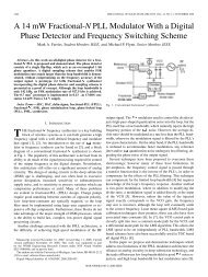
A block diagram of the proposed AD<strong>PLL</strong> is shown in Fig. 1.<br />
The TDC compares the edges of the reference clock (F ref ) and<br />
the divided output clock (F div ), and provides 16-bit phase<br />
difference measurements to the digital loop filter (DLF). The<br />
proposed TDC operates in two steps; a coarse step and a fine<br />
step, producing 8-bit MSBs and 8-bit LSBs, respectively. The<br />
prescaler combines this output by weighting the MSBs and the<br />
LSBs separately, making a 16-bit input to the DLF. This<br />
enables floating point processing of the TDC output, and<br />
provides more programmability of the coarse/fine step<br />
resolutions. The DLF consists of a proportional path and an<br />
integral path, each with programmable coefficients. The 3-bit<br />
MSBs of the DLF output determine whether the DCO<br />
controller increases, decreases, or holds the DCO frequency.<br />
The 8-bit LSBs of the DLF output are used to dither the DCO<br />
frequency to reduce the effect of limit cycles. The dithering<br />
block is clocked at a higher frequency of F out /4. Finally, F out is<br />
divided by an integer N (1-to-511), and compared with F ref . In<br />
calibration mode, on-chip counters are used for one-time<br />
characterization of the TDC and the DCO, which is later used<br />
to control them in locking mode.<br />
978-1-4577-0223-5/11/$26.00 ©2011 <strong>IEEE</strong>
Mem<br />
6<br />
3<br />
DCO<br />
Controller<br />
addr<br />
30<br />
x64<br />
Buffer<br />
index<br />
data<br />
8<br />
Dithering<br />
2<br />
317<br />
stage1 stage2 stage3 stage4 stage5<br />
64 buffers/<br />
stage<br />
63 63+1 63+1 64 64<br />
Start /<br />
Stop<br />
Fig. 1. Block diagram of proposed AD<strong>PLL</strong>.<br />
Stage 1 Stage 2 Stage 3<br />
Stage 4 Stage 5<br />
A. Cell-based DCO<br />
<strong>All</strong> blocks, including the DCO, are constructed only of<br />
standard cells and synthesized <strong>from</strong> a cell library. Fig. 2 shows<br />
the block diagram of the DCO and the DCO control blocks. The<br />
DCO consists of 5 stages, and each stage is implemented with<br />
64 inverting tri-state buffers connected in parallel (63 buffers<br />
and one NAND gate in Stage1). The maximum frequency is<br />
obtained when all buffers are turned on, and the frequency is<br />
reduced by turning off buffers. Instead of custom layout to<br />
achieve matched delays [6-8], the buffers in the DCO are<br />
automatically laid out by design tools. This introduces<br />
systematic mismatch between buffer delays which was found<br />
through measurements to be dominated by wire routing<br />
variation. In calibration mode, the effective drive strength of<br />
each buffer is measured, capturing the relative differences<br />
between buffers. Then, buffers are sorted based on drive<br />
strength, and the reordered indexes are stored in a local<br />
memory. The DCO controller decodes one row of the memory<br />
each cycle, and turns on/off the indexed buffers according to<br />
the DLF output. This reordering procedure provides a<br />
coarse/fine frequency control, and improves the resolution of<br />
the DCO. The dithering block generates 2-bit control signals to<br />
pseudo-randomly turn on/off the buffers at a rate proportional<br />
to the 8 LSBs of the DLF output. Two buffers in Stage2 and<br />
Stage3 are dedicated to dithering the DCO frequency.<br />
B. Cell-based TDC<br />
We use a DCO-based Vernier TDC to measure the phase<br />
difference between F ref and F div , and the details of the TDC<br />
architecture and operation are described in [14]. As shown in<br />
Fig. 3, the TDC employs two DCOs with slightly different<br />
periods, and the phase difference is measured in two steps. First,<br />
the coarse time difference is measured by counting the number<br />
of slow DCO cycles between the two rising edges. Second, the<br />
residue of the time difference is measured by counting the<br />
number of fast DCO cycles during the time it takes the fast<br />
DCO to catch up to the slow DCO. The coarse step resolution is<br />
the slow DCO period, and the fine step resolution is the<br />
difference between the fast and slow DCO periods. The two<br />
step measurement and ring structure allows for an extended<br />
DCO<br />
Fig. 2. Block diagram of DCO and DCO control block.<br />
Fig. 3. Block diagram of TDC and coarse/fine steps.<br />
detection range, and the Vernier structure using two DCOs<br />
provides a fine resolution. We adopt a similar structure for the<br />
DCOs as shown in Fig. 2, and apply a similar ordering of<br />
buffers based on effective drive strength. The measured coarse<br />
step resolution can be tuned between 160ps and 1ns, and the<br />
fast and slow DCOs are controlled together for the fine step<br />
resolution, which can be as low as 8ps.<br />
III. CALIBRATION SCHEME UTILIZING SYSTEMATIC<br />
MISMATCH<br />
Fig. 4 illustrates the DCO control scheme to address<br />
systematic mismatch caused by automatic P&R. The<br />
systematic mismatch is measured in terms of incremental<br />
period, which is defined as increase in period when only one<br />
buffer is turned off. Each buffer has a unique incremental<br />
period value, implying an effective drive strength of the buffer.<br />
The measured incremental periods for the 62 buffers in Stage1<br />
of the DCO are shown in Fig. 4. The buffers in each stage are<br />
reordered based on the incremental periods and stored in the<br />
memory while in calibration mode. When the AD<strong>PLL</strong> is in<br />
locking mode, the DCO controller turns off the buffers<br />
following the order stored in memory. During coarse control, 5<br />
buffers at a time are turned off <strong>from</strong> the top of the memory,<br />
which have the highest drive strengths. During fine control,<br />
only one buffer at a time is turned off <strong>from</strong> the bottom of the<br />
memory, which has the lowest drive strengths. The coarse
Turn off<br />
5 buffers<br />
at a step<br />
Coarse<br />
range<br />
Turn off<br />
one buffer<br />
at a step<br />
Reorder<br />
buffers<br />
and<br />
store index<br />
in memory<br />
Coarse control<br />
Mem<br />
Mem<br />
off<br />
Fine control<br />
Buffer index<br />
54<br />
48<br />
33<br />
32<br />
on<br />
Incremental period (ps)<br />
Frequency (GHz)<br />
1.5<br />
0.5<br />
0<br />
0 10 20 30 40 50 60<br />
2.8<br />
2.6<br />
2.4<br />
2.2<br />
1.8<br />
0 20 40 60 80 100<br />
Fig. 4. Calibration algorithm utilizing systematic mismatch.<br />
control range is programmable by the starting memory address,<br />
which enables fast-locking at a target frequency range. The fine<br />
control achieves higher resolution by turning off buffers with<br />
the lowest drive strength. Fig. 4 shows the measured frequency<br />
response for 3 different coarse settings (branches off the steep<br />
slope), with fine-tuning applied afterwards (shallow slopes).<br />
The measured fine-frequency resolution is 3MHz/step at<br />
2.5GHz.<br />
This coarse/fine frequency control is obtained due to<br />
systematic mismatch by automatic P&R. If the buffers and<br />
wiring were completely matched, the incremental periods of<br />
the buffers would all be the same, and a coarse/fine tuning<br />
would not be possible. Instead, the frequency would be<br />
determined only by the absolute number of enabled buffers,<br />
regardless of which ones were used. The proposed calibration<br />
scheme therefore leverages the systematic wiring mismatch by<br />
reordering buffers to achieve better resolution at desired coarse<br />
frequency bands.<br />
To address the sensitivity of the synthesized AD<strong>PLL</strong> over<br />
environmental variations, the DCO frequency control is<br />
measured over PVT variation as shown in Fig. 5. The DCO<br />
frequency varies less than 10% and 15% over the voltage and<br />
temperature variation, respectively. The maximum DCO<br />
frequencies of 5 chips are also measured to address process<br />
variation. The mean of the maximum frequency is 2.9GHz with<br />
a standard deviation is 37.4MHz. The above PVT variation is<br />
within a few coarse control steps in the proposed calibration<br />
scheme, and can be overcome by the broad DCO frequency<br />
range and its programmability when the AD<strong>PLL</strong> operates in<br />
closed-loop.<br />
The proposed calibration scheme requires a consistent order<br />
of the buffers over supply voltage and temperature variations,<br />
since the index of buffers is reordered and stored in the memory<br />
while in calibration mode, and remains during the AD<strong>PLL</strong><br />
locking mode. Since the systematic mismatch is dominant in<br />
the automatically P&R-ed DCO, the order of the buffers’ drive<br />
strengths is relatively consistent over environmental variations<br />
1<br />
3<br />
2<br />
Mismatch<br />
between buffers<br />
Index of buffers (stage 1)<br />
3MHz/step<br />
Control step<br />
Frequency (GHz)<br />
Frequency (GHz)<br />
4<br />
3<br />
2<br />
1<br />
0<br />
0 50 100 150 200 250 300<br />
4<br />
3<br />
2<br />
1<br />
0<br />
0 50 100 150 200 250 300<br />
0<br />
2.8 2.85 2.9 2.95<br />
Fig. 5. Measured DCO frequency control over (a) voltage, (b) temperature, and<br />
(c) process variation.<br />
1.5<br />
1<br />
0.5<br />
0<br />
0 10 20 30 40 50 60<br />
Index of buffers<br />
(a)<br />
1.5<br />
1<br />
0.5<br />
1.10V<br />
1.05V<br />
1.15V<br />
25°C<br />
-40°C<br />
80°C<br />
0<br />
0 10 20 30 40 50 60<br />
Index of buffers<br />
(b)<br />
Fig. 6. Measured incremental period of buffers in Stage1 over (a) voltage, (b)<br />
temperature, and (c) process variation.<br />
as shown in Fig. 6 by the same relative shapes of the<br />
incremental periods, resulting in the same sorted order. Thus,<br />
the reordering process can be done once per chip, and applied<br />
to the frequency control.<br />
IV. MEASURED AD<strong>PLL</strong> PERFORMANCE<br />
The AD<strong>PLL</strong> was fabricated in 65nm CMOS, and the<br />
micrograph is shown in Fig. 7. The active area of the AD<strong>PLL</strong> is<br />
185x190μm 2 , and the memory occupies an additional area of<br />
90x85μm 2 . The AD<strong>PLL</strong> operates at 1.1V, and the output<br />
frequency locks <strong>from</strong> 1.5GHz to 2.7GHz by controlling F ref and<br />
the divider N, which ranges <strong>from</strong> 1 to 511. In this measurement,<br />
F ref is set to 10MHz, and N is programmed to be 250 to lock the<br />
frequency at 2.5GHz. Fig. 8 shows the measured output clock<br />
signal and the period jitter histogram at 2.5GHz. The period<br />
jitter is the main figure of merit for clock synthesis, and it is<br />
measured with an oscilloscope. Over 275K samples, the RMS<br />
and peak-to-peak jitters are 3.2ps rms and 36ps pp , respectively.<br />
Fig. 8 also shows the power consumption of the AD<strong>PLL</strong>. It<br />
dissipates 4.6mW/GHz over the frequency range with an offset<br />
Count<br />
2<br />
1.5<br />
1<br />
0.5
TABLE I<br />
PERFORMANCE SUMMARY<br />
Process<br />
This work [4] [5] [6]<br />
65nm<br />
CMOS<br />
65nm<br />
CMOS<br />
65nm<br />
CMOS<br />
65nm<br />
CMOS<br />
Area 0.042mm 2 0.045mm 2 0.027mm 2 0.048mm 2<br />
Supply 1.1V 1.3/1.1V 1.1-1.3V 1.2V<br />
Power<br />
13.7mW<br />
@2.5GHz<br />
11.6mW<br />
@3GHz<br />
-<br />
19.7mW<br />
@2GHz<br />
Fig. 7. Die micrograph of AD<strong>PLL</strong><br />
Output<br />
Frequency<br />
1.5 to<br />
2.7GHz<br />
0.19 to<br />
4.27GHz<br />
600 to<br />
800MHz<br />
1 to 2GHz<br />
6 x 10⁴<br />
Jitter<br />
3.2ps rms<br />
@2.5GHz<br />
1.4ps rms<br />
@3GHz<br />
21ps rms<br />
@800MHz<br />
1.0ps rms<br />
@2GHz<br />
5<br />
36ps pp<br />
@2.5GHz<br />
15ps pp<br />
@3GHz<br />
193ps pp<br />
@800MHz<br />
16.6ps pp<br />
@2GHz<br />
4<br />
Power (mW)<br />
15<br />
14<br />
13<br />
12<br />
11<br />
10<br />
9<br />
0<br />
-20 -10 0 10 20<br />
1.6 1.8 2 2.2 2.4 2.6<br />
Fig. 8. Measured output clock signal and jitter histogram at 2.5GHz (top) and<br />
Power consumption of AD<strong>PLL</strong> over output frequency range (bottom).<br />
of 2.2mW. The performance of the AD<strong>PLL</strong> is summarized in<br />
Table I.<br />
V. CONCLUSION<br />
A synthesizable AD<strong>PLL</strong> for clock generation is designed and<br />
fabricated in a 65nm CMOS process. <strong>All</strong> functional blocks are<br />
implemented with digital standard cells and automatically<br />
P&R-ed. Systematic mismatch by automatic P&R is measured<br />
in terms of incremental periods, and utilized to improve<br />
resolution at target frequencies. A calibration scheme exploits<br />
the systematic mismatch to improve the performance. The<br />
proposed cell-based design of AD<strong>PLL</strong> leverages standard cell<br />
engineering and design automation to enhance productivity in<br />
advanced process technologies, and the measured performance<br />
of the AD<strong>PLL</strong> is comparable to other full-custom designs.<br />
REFERENCES<br />
[1] A-J. <strong>An</strong>nema, B. Nauta, R. Langevelde, and H. Tuinhout, “<strong>An</strong>alog<br />
Circuits in Ultra-Deep-Submicron CMOS,” <strong>IEEE</strong> Journal of Solid-State<br />
Circuits, vol.40, no. 1, Jan. 2005.<br />
[2] L. L. Lewyn, T. Ytterdal, C. Wulff, and K. Martin, “<strong>An</strong>alog Circuit<br />
Design in Nanoscale CMOS Technologies,” Proc. of <strong>IEEE</strong>, pp.<br />
1687-1714, 2009.<br />
Hits<br />
3<br />
2<br />
1<br />
[3] B. Murmann, P. Nikaeen, D. J. Connelly, and R. W. Dutton, “Impact of<br />
Scaling on <strong>An</strong>alog Performance and Associated Modeling Needs,” Trans.<br />
Electron Devices, vol. 53, no. 9, Sep. 2006.<br />
[4] W. Grollitsch, R. Nonis, and N.D. Dalt, “A 1.4ps rms-Period-Jitter<br />
TDC-Less Fractional-N <strong>Digital</strong> <strong>PLL</strong> with <strong>Digital</strong>ly Controlled Ring<br />
Oscillator in 65nm CMOS,” ISSCC Dig. Tech. Papers, pp. 478-479, Feb.<br />
2010.<br />
[5] M.S-W. Chen, D. Su, and S. Mehta, “A Calibration-Free 800MHz<br />
Fractional-N <strong>Digital</strong> <strong>PLL</strong> with Embedded TDC,” ISSCC Dig. Tech.<br />
Papers, pp. 472-473, Feb. 2010.<br />
[6] A.V. Rylyakov, J.A. Tierno, D.Z. Turker, J-O. Plouchart, H.A. Ainspan,<br />
and D. Friedman, “A Modular <strong>All</strong>-<strong>Digital</strong> <strong>PLL</strong> architecture Enabling<br />
Both 1-to-2GHz and 24-to-32GHz Operation in 65nm CMOS,” ISSCC<br />
Dig. Tech. Papers, pp. 516-517, Feb. 2008.<br />
[7] J.A. Tierno, A.V. Rylyakov, and D. Friedman, “A Wide Power Supply<br />
Range, Wide Tuning Range, <strong>All</strong> Static CMOS <strong>All</strong> <strong>Digital</strong> <strong>PLL</strong> in 65 nm<br />
SOI,” <strong>IEEE</strong> J. Solid-State Circuits, vol. 43, no. 1, pp. 42-51, Jan. 2008.<br />
[8] T. Olsson and P. Nilsson, “A <strong>Digital</strong>ly Controlled <strong>PLL</strong> for SoC<br />
Application,” <strong>IEEE</strong> J. Solid-State Circuits, vol. 39, pp. 751-760, May.<br />
2004.<br />
[9] C. Weltin-Wu, E. Temporiti, D. Baldi, M. Cusmai, and F. Svelto, “A<br />
3.5GHz Wideband AD<strong>PLL</strong> with Fractional Spur Suppression Through<br />
TDC Dithering and Feedforward Compensation,” <strong>IEEE</strong> Int. Solid-State<br />
Circuits Conf. Dig. Tech. Papers, pp. 468-469, Feb., 2010.<br />
[10] T. Tokairin, M. Okada, M. Kitsunezuka, T. Maeda, and M. Fukaishi, “A<br />
2.1-to-2.8GHz <strong>All</strong>-<strong>Digital</strong> Frequency Synthesizer with a<br />
Time-Windowed TDC,” <strong>IEEE</strong> Int. Solid-State Circuits Conf. Dig. Tech.<br />
Papers, pp. 470-471, Feb., 2010.<br />
[11] J. Borremans, K. Vengattaramane, V. Giannini, and Jan. Craninckx, “A<br />
86MHz-to-12GHz <strong>Digital</strong>ly-Intensive Phase-Modulated Fractional-N<br />
<strong>PLL</strong> Using a 15pJ/Shot 5ps TDC in 40nm digital CMOS,” <strong>IEEE</strong> Int.<br />
Solid-State Circuits Conf. Dig. Tech. Papers, pp. 480-481, Feb., 2010.<br />
[12] C. Hsu, M. Z. Straayer, and M. H. Perrott, “A Low-Noise Wide-BW<br />
3.6-GHz <strong>Digital</strong> ∆∑ Fractional-N Frequency Synthesizer With a<br />
Noise-Shaping Time-to-<strong>Digital</strong> Converter and Quantization Noise<br />
Cancellation,” <strong>IEEE</strong> Journal of Solid State Circuits, vol. 43, no. 12, pp.<br />
2776-2786, Dec. 2008.<br />
[13] V. Kheterpal et al., “Design methodology for IC manufacturability based<br />
on regular logic-bricks,” in Proc. ACM/<strong>IEEE</strong> Design Automation Conf.,<br />
pp. 353-358, Jun. 2005.<br />
[14] Y. Park and David D. Wentzloff, “A Cyclic Vernier Time-to-<strong>Digital</strong><br />
Converter <strong>Synthesized</strong> <strong>from</strong> a 65nm CMOS standard library”, <strong>IEEE</strong> Int.<br />
Symposium on Circuits and Systems, pp. 3561-3564, Jun. 20.


![[Sample B: Approval/Signature Sheet]](https://img.yumpu.com/34084789/1/190x245/sample-b-approval-signature-sheet.jpg?quality=85)