HARTING - Northern Connectors
HARTING - Northern Connectors
HARTING - Northern Connectors

You also want an ePaper? Increase the reach of your titles
YUMPU automatically turns print PDFs into web optimized ePapers that Google loves.
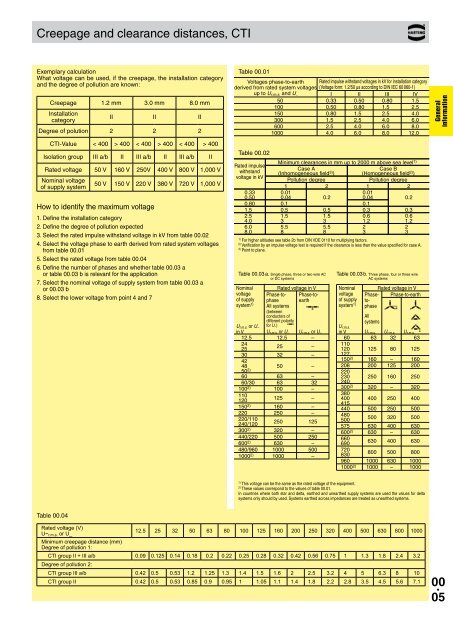
Creepage and clearance distances, CTI<br />
Exemplary calculation<br />
What voltage can be used, if the creepage, the installation category<br />
and the degree of pollution are known:<br />
Creepage 1.2 mm 3.0 mm 8.0 mm<br />
Installation<br />
category<br />
II II II<br />
Degree of polution 2 2 2<br />
CTI-Value < 400 > 400 < 400 > 400 < 400 > 400<br />
Isolation group III a/b II III a/b II III a/b II<br />
Rated voltage 50 V 160 V 250V 400 V 800 V 1,000 V<br />
Nominal voltage<br />
of supply system<br />
50 V 150 V 220 V 380 V 720 V 1,000 V<br />
How to identify the maximum voltage<br />
1. Define the installation category<br />
2. Define the degree of pollution expected<br />
3. Select the rated impulse withstand voltage in kV from table 00.02<br />
4. Select the voltage phase to earth derived from rated system voltages<br />
from table 00.01<br />
5. Select the rated voltage from table 00.04<br />
6. Define the number of phases and whether table 00.03 a<br />
or table 00.03 b is relevant for the application<br />
7. Select the nominal voltage of supply system from table 00.03 a<br />
or 00.03 b<br />
8. Select the lower voltage from point 4 and 7<br />
Table 00.01<br />
Voltages phase-to-earth Rated impulse withstand voltages in kV for installation category<br />
derived from rated system voltages (Voltage form: 1.2/50 µs according to DIN IEC 60 060-1)<br />
up to U r.m.s. and U – I II III IV<br />
50 0.33 0.50 0.80 1.5<br />
100 0.50 0.80 1.5 2.5<br />
150 0.80 1.5 2.5 4.0<br />
300 1.5 2.5 4.0 6.0<br />
600 2.5 4.0 6.0 8.0<br />
1000 4.0 6.0 8.0 12.0<br />
Table 00.02<br />
Minimum clearances in mm up to 2000 m above sea level<br />
Rated impulse<br />
1)<br />
Case A<br />
Case B<br />
withstand (Inhomogeneous field 3) ) (Homogeneous field 2) )<br />
voltage in kV<br />
Pollution degree<br />
Pollution degree<br />
1 2 1 2<br />
0.33 0.01 0.01<br />
0.50 0.04 0.2 0.04 0.2<br />
0.80 0.1 0.1<br />
1.5 0.5 0.5 0.3 0.3<br />
2.5 1.5 1.5 0.6 0.6<br />
4.0 3 3 1.2 1.2<br />
6.0 5.5 5.5 2 2<br />
8.0 8 8 3 3<br />
1) For higher altitudes see table 2b from DIN VDE 0110 for multiplying factors.<br />
2) Verification by an impulse voltage test is required if the clearance is less than the value specified for case A.<br />
3) Point to plane.<br />
Table 00.03 a. Single phase, three or two wire AC<br />
or DC systems<br />
Nominal<br />
voltage<br />
of supply<br />
system 1)<br />
Rated voltage in V<br />
Phase-tophase<br />
Phase-toearth<br />
All systems<br />
(between<br />
conduc tors of<br />
different polarity<br />
U r.m.s. or U –<br />
in V<br />
for U – )<br />
U r.m.s. or U –<br />
12.5 12.5 –<br />
24<br />
25 –<br />
25<br />
30 32 –<br />
42<br />
48 50 –<br />
50 2)<br />
60 63 –<br />
60/30 63 32<br />
100 2) 100 –<br />
110<br />
120<br />
125 –<br />
150 2) 160 –<br />
220 250 –<br />
220/110<br />
240/120<br />
250 125<br />
300 2) 320 –<br />
440/220 500 250<br />
600 2) 630 –<br />
480/960 1000 500<br />
1000 2) 1000 –<br />
Table 00.03 b. Three phase, four or three wire<br />
AC systems<br />
Nominal<br />
voltage<br />
of supply<br />
system 1)<br />
U r.m.s.<br />
Rated voltage in V<br />
Phaseto-<br />
Phase-to-earth<br />
phase<br />
All<br />
systems<br />
U r.m.s. or U – in V U r.m.s. U r.m.s. U r.m.s.<br />
60 63 32 63<br />
110<br />
120 125 80 125<br />
127<br />
150 2) 160 – 160<br />
208 200 125 200<br />
220<br />
230 250 160 250<br />
240<br />
300 2) 320 – 320<br />
380<br />
400 400 250 400<br />
415<br />
440 500 250 500<br />
480<br />
500<br />
500 320 500<br />
575 630 400 630<br />
600 2) 630 – 630<br />
660<br />
690<br />
630 400 630<br />
720<br />
830<br />
800 500 800<br />
960 1000 630 1000<br />
1000 2) 1000 – 1000<br />
General<br />
information<br />
1) This voltage can be the same as the rated voltage of the equipment.<br />
2) These values correspond to the values of table 00.01.<br />
In countries where both star and delta, earthed and unearthed supply systems are used the values for delta<br />
systems only should by used. Systems earthed across impedances are treated as unearthed systems.<br />
Table 00.04<br />
Rated voltage (V)<br />
U~ r.m.s. or U_<br />
12.5 25 32 50 63 80 100 125 160 200 250 320 400 500 630 800 1000<br />
Minimum creepage distance (mm)<br />
Degree of pollution 1:<br />
CTI group II + III a/b 0.09 0.125 0.14 0.18 0.2 0.22 0.25 0.28 0.32 0.42 0.56 0.75 1 1.3 1.8 2.4 3.2<br />
Degree of pollution 2:<br />
CTI group III a/b 0.42 0.5 0.53 1.2 1.25 1.3 1.4 1.5 1.6 2 2.5 3.2 4 5 6.3 8 10<br />
CTI group II 0.42 0.5 0.53 0.85 0.9 0.95 1 1.05 1.1 1.4 1.8 2.2 2.8 3.5 4.5 5.6 7.1<br />
00 .<br />
05