HARTING - Northern Connectors
HARTING - Northern Connectors
HARTING - Northern Connectors

You also want an ePaper? Increase the reach of your titles
YUMPU automatically turns print PDFs into web optimized ePapers that Google loves.
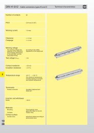
Technical characteristics<br />
Type H<br />
Number of contacts 15, 16<br />
14 + 1 leading contact<br />
(position z 32)<br />
13 + 2 leading contacts<br />
(position z 4 und z 32)<br />
3<br />
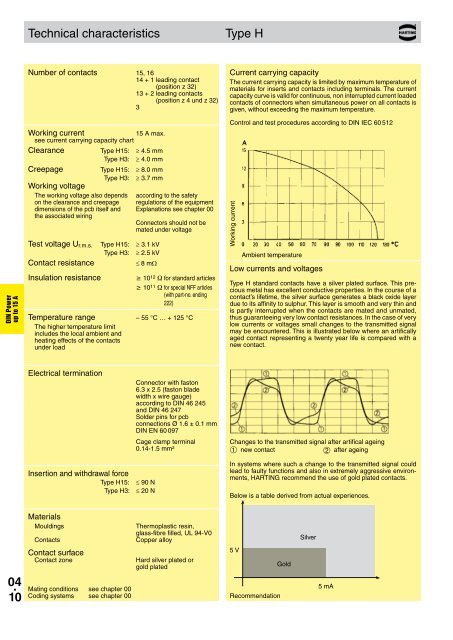
Current carrying capacity<br />
The current carrying capacity is limited by maximum temperature of<br />
materials for inserts and contacts including terminals. The current<br />
capacity curve is valid for continuous, non interrupted current loaded<br />
contacts of connectors when simultaneous power on all contacts is<br />
given, without exceeding the maximum temperature.<br />
DIN Power<br />
up to 15 A<br />
Working current<br />
15 A max.<br />
see current carrying capacity chart<br />
Clearance<br />
Type H15: ≥ 4.5 mm<br />
Type H3: ≥ 4.0 mm<br />
Creepage<br />
Type H15: ≥ 8.0 mm<br />
Type H3: ≥ 3.7 mm<br />
Working voltage<br />
The working voltage also depends according to the safety<br />
on the clearance and creepage regulations of the equipment<br />
dimensions of the pcb itself and Explanations see chapter 00<br />
the associated wiring<br />
<strong>Connectors</strong> should not be<br />
mated under voltage<br />
Test voltage U r.m.s.<br />
Contact resistance<br />
Insulation resistance<br />
Type H15: ≥ 3.1 kV<br />
Type H3: ≥ 2.5 kV<br />
≤ 8 mΩ<br />
³ 10 12 W for standard articles<br />
³ 10 11 W for special NFF articles<br />
(with part-no. ending<br />
222)<br />
Temperature range – 55 °C … + 125 °C<br />
The higher temperature limit<br />
includes the local ambient and<br />
heating effects of the contacts<br />
under load<br />
Control and test procedures according to DIN IEC 60 512<br />
Working current<br />
Ambient temperature<br />
Low currents and voltages<br />
Type H standard contacts have a silver plated surface. This precious<br />
metal has excellent conductive properties. In the course of a<br />
contact’s lifetime, the silver surface generates a black oxide layer<br />
due to its affinity to sulphur. This layer is smooth and very thin and<br />
is partly interrupted when the contacts are mated and unmated,<br />
thus guaranteeing very low contact resistances. In the case of very<br />
low currents or voltages small changes to the transmitted signal<br />
may be encountered. This is illustrated below where an artifically<br />
aged contact representing a twenty year life is compared with a<br />
new contact.<br />
Electrical termination<br />
Insertion and withdrawal force<br />
Type H15: ≤ 90 N<br />
Type H3: ≤ 20 N<br />
Connector with faston<br />
6.3 x 2.5 (faston blade<br />
width x wire gauge)<br />
according to DIN 46 245<br />
and DIN 46 247<br />
Solder pins for pcb<br />
connections Ø 1.6 ± 0.1 mm<br />
DIN EN 60 097<br />
Cage clamp terminal<br />
0.14-1.5 mm²<br />
Changes to the transmitted signal after artifical ageing<br />
➀ new contact<br />
after ageing<br />
In systems where such a change to the transmitted signal could<br />
lead to faulty functions and also in extremely aggressive environments,<br />
<strong>HARTING</strong> recommend the use of gold plated contacts.<br />
➁<br />
Below is a table derived from actual experiences.<br />
Materials<br />
Mouldings<br />
Contacts<br />
Contact surface<br />
Contact zone<br />
Thermoplastic resin,<br />
glass-fibre filled, UL 94-V0<br />
Copper alloy<br />
Hard silver plated or<br />
gold plated<br />
5 V<br />
Gold<br />
Silver<br />
04 .<br />
10<br />
Mating conditions see chapter 00<br />
Coding systems see chapter 00<br />
Recommendation<br />
5 mA