HARTING - Northern Connectors
HARTING - Northern Connectors
HARTING - Northern Connectors

Create successful ePaper yourself
Turn your PDF publications into a flip-book with our unique Google optimized e-Paper software.
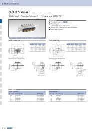
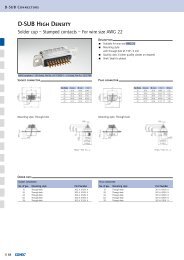
Specifications, assembly instructions<br />
General<br />
information<br />
Performance level 3 as per IEC 60 603-2<br />
50 mating cycles then visual inspection.<br />
No gas test.<br />
No functional impairment.<br />
Part No. explanation 09 . . . . . 7 . . .<br />
Performance level 2 as per IEC 60 603-2<br />
400 mating cycles.<br />
200 mating cycles then 4 days gas test using 10 ppm SO 2 .<br />
Measurement of contact resistance.<br />
200 mating cycles then visual inspection. No abrasion of the<br />
contact finish through to the base material.<br />
No functional impairment.<br />
Part No. explanation 09 . . . . . 6 . . .<br />
Performance level 1 as per IEC 60 603-2<br />
500 mating cycles.<br />
250 mating cycles then 10 days gas test using 10 ppm SO 2 .<br />
Measurement of contact resistance.<br />
250 mating cycles then visual inspection. No abrasion of the<br />
contact finish through to the base material.<br />
No functional impairment.<br />
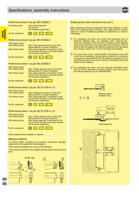
Soldering the male connectors into pcb´s<br />
Male connectors should be protected when being soldered in a dip,<br />
flow or film soldering baths. Otherwise, they might become contaminated<br />
as a result of soldering operations or deformed as a result of<br />
overheating.<br />
➀ For prototypes and short runs protect the connectors with an<br />
indus trial adhesive tape, e.g. Tesaband 4331 (www.tesa.de).<br />
Cover the underside of the connector moulding and the adjacent<br />
parts of the pcb as well as the open sides of the connector. This will<br />
prevent heat and gases of the soldering apparatus from damaging<br />
the connector. About 140 + 5 mm of the tape should suffice.<br />
➁ For large series a jig is recommended. Its protective cover with<br />
a fast action mechanical locking device shields the connectors<br />
from gas and heat generated by the sol dering apparatus. As an<br />
additional protection a foil can be used for cov ering the parts that<br />
should not be soldered.<br />
➂ For prototypes and short runs the protection described under<br />
point ➀ can be replaced by a solder protection cap. This cap can<br />
be ordered under the part no. 09 02 000 9935.<br />
Part No. explanation 09 . . . . . 2 . . .<br />
Performance level 2 as per IEC 61 076-4-113<br />
250 mating cycles.<br />
125 mating cycles then 4 days gas test using 10 ppm SO 2 .<br />
Measurement of contact resistance.<br />
125 mating cycles then visual inspection. No abrasion of the<br />
contact finish through to the base material.<br />
No functional impairment.<br />
Part No. explanation 02 . . . . . 2 . . .<br />
➀ + ➂<br />
Adhesive tape or<br />
protection cap<br />
Performance level 1 as per IEC 61 076-4-113<br />
500 mating cycles.<br />
250 mating cycles then 10 days gas test using 10 ppm SO 2 .<br />
Measurement of contact resistance.<br />
250 mating cycles then visual inspection. No abrasion of the<br />
contact finish through to the base material.<br />
No functional impairment.<br />
Part No. explanation 02 . . . . . 1 . . .<br />
Intermediate foil<br />
Other plating finishes available on request.<br />
Mating conditions<br />
To ensure reliable connections and prevent unnecessary damage,<br />
please refer to the application data diagrams.<br />
These recommendations are set out in IEC 60 603-2.<br />
The connectors should not be coupled and decoupled under electrical<br />
load.<br />
➁<br />
00 .<br />
06