HARTING - Northern Connectors
HARTING - Northern Connectors
HARTING - Northern Connectors

You also want an ePaper? Increase the reach of your titles
YUMPU automatically turns print PDFs into web optimized ePapers that Google loves.
Terminations<br />
Crimp terminals<br />
General<br />
information<br />
A perfect crimp connection is gastight and therefore corrosion free. It is<br />
equivalent to a cold weld of the connected parts. For this reason, major<br />
features in achieving high quality crimp connections are the design of<br />
the crimping areas of the contact and of course the crimping tool it self.<br />
Wires to be connected must be carefully matched to the correct size<br />
of crimp contacts. If these basic requirements are met, users will be<br />
assured of highly reliable connections with a low contact resistance<br />
and a high resistance against corrosion.<br />
Crimp cross-section<br />
The economical and technical advantages are:<br />
● Constant contact resistance as a result of an unvariable crimp<br />
connection quality<br />
● Corrosion free connections as a result of cold weld action<br />
● Preparation of harnessing with crimp contacts already fitted<br />
● More economic cable connection<br />
Requirements for crimp connections are set out in DIN IEC 60 352-2.<br />
Pull out force of stranded wire<br />
The main criterion by which to judge the quality of a crimp connection<br />
is the retention force achieved by the wire conductor in the terminal<br />
section of the contact. DIN IEC 60 352, part 2, defines the extraction<br />
force in relation to the cross-section of the conductor. When fitted using<br />
<strong>HARTING</strong> crimping tools and subject to their utilization in an approved<br />
manner, our crimp connectors comply with the required extraction<br />
forces.<br />
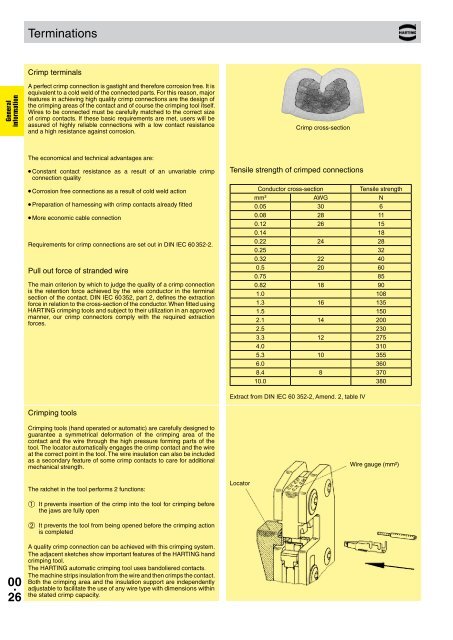
Tensile strength of crimped connections<br />
Conductor cross-section<br />
Tensile strength<br />
mm² AWG N<br />
0.05 30 6<br />
0.08 28 11<br />
0.12 26 15<br />
0.14 18<br />
0.22 24 28<br />
0.25 32<br />
0.32 22 40<br />
0.5 20 60<br />
0.75 85<br />
0.82 18 90<br />
1.0 108<br />
1.3 16 135<br />
1.5 150<br />
2.1 14 200<br />
2.5 230<br />
3.3 12 275<br />
4.0 310<br />
5.3 10 355<br />
6.0 360<br />
8.4 8 370<br />
10.0 380<br />
Extract from DIN IEC 60 352-2, Amend. 2, table IV<br />
Crimping tools<br />
Crimping tools (hand operated or automatic) are carefully designed to<br />
guarantee a symmetrical deformation of the crimping area of the<br />
contact and the wire through the high pressure forming parts of the<br />
tool. The locator automatically engages the crimp contact and the wire<br />
at the correct point in the tool. The wire insulation can also be included<br />
as a secondary feature of some crimp contacts to care for additional<br />
mechanical strength.<br />
Wire gauge (mm²)<br />
The ratchet in the tool performs 2 functions:<br />
Locator<br />
➀ It prevents insertion of the crimp into the tool for crimping before<br />
the jaws are fully open<br />
➁ It prevents the tool from being opened before the crimping action<br />
is completed<br />
00 .<br />
26<br />
A quality crimp connection can be achieved with this crimping system.<br />
The adjacent sketches show important features of the <strong>HARTING</strong> hand<br />
crimping tool.<br />
The <strong>HARTING</strong> automatic crimping tool uses bandoliered contacts.<br />
The machine strips insulation from the wire and then crimps the contact.<br />
Both the crimping area and the insulation support are independently<br />
adjustable to facilitate the use of any wire type with dimensions within<br />
the stated crimp capacity.