HARTING - Northern Connectors
HARTING - Northern Connectors
HARTING - Northern Connectors

Create successful ePaper yourself
Turn your PDF publications into a flip-book with our unique Google optimized e-Paper software.
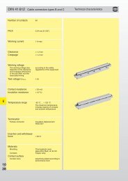
Technical characteristics<br />
Types B, 2B, 3B, C, 2C, 3C, M, M invers,<br />
Q, 2Q, R, R (HE 11), 2R<br />
DIN Signal<br />
up to 2 A<br />
Number of contacts 16-96<br />
Contact spacing (mm) 2.54<br />
Working current<br />
2 A max.<br />
see current carrying<br />
1 A with insulation displacement<br />
capacity chart<br />
40 A max. type M<br />
Clearance<br />
³ 1.2 mm<br />
Creepage<br />
³ 1.2 mm<br />
Working voltage<br />
The working voltage also depends according to the safety regulations<br />
on the clearance and creepage of the equipment<br />
dimensions of the pcb itself, Explanations see chapter 00<br />
and the associated wiring<br />
Test voltage U r.m.s.<br />
1 kV<br />
Contact resistance £ 20 mW<br />
Insulation resistance ³ 10 12 W for standard articles<br />
³ 10 11 W for special NFF articles<br />
(with part-no. ending 222)<br />
Temperature range – 55 °C … + 125 °C<br />
The higher temperature limit – 40 °C … + 105 °C<br />
includes the local ambient for press-in connector<br />
and heating effects of the<br />
contacts under load<br />
During reflow soldering max. + 240 °C for 15 s<br />
for SMC connectors<br />
Degree of protection for crimp terminal IP 20<br />
according to DIN 40 050<br />
Electrical termination<br />
Male and female connector<br />
Compliant press-in<br />
terminations<br />
PCB thickness<br />
Solder pins for pcb connections<br />
Ø 1.0 ± 0.1 mm<br />
according to IEC 60 326-3<br />
wrap posts 0.6 x 0.6 mm<br />
diagonal 0.79-0.86 mm<br />
Crimp terminal 0.09-0.5 mm²<br />
Insulation displacement<br />
connection AWG 28/7<br />
³ 1.6 mm<br />
Recommended PCB holes See recommendation page 00.25<br />
for press-in technology in acc. to EN 60 352-5<br />
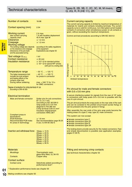
Current carrying capacity<br />
The current carrying capacity is limited by maximum temperature of<br />
materials for inserts and contacts including terminals. The current<br />
capacity curve is valid for continuous, non interrupted current loaded<br />
contacts of connectors when simultaneous power on all contacts is<br />
given, without exceeding the maximum temperature.<br />
Control and test procedures according to DIN IEC 60 512<br />
Working current<br />
Ambient temperature<br />
Pin shroud for male and female connectors<br />
with 0.6 x 0.6 mm pins<br />
A secure interfacing system for signals from the rear of 19” racks<br />
to connectors with wrap posts 0.6 x 0.6 mm is possible with the<br />
use of a pin shroud.<br />
The pin shroud protects the wrap posts on the rear side of the rack<br />
and can be screwed to the printed circuit board (screw fixing) or<br />
can be pressed onto the pins (press-in fixing).<br />
After assembly the rear ends of the wire wrap posts become the<br />
mating areas of a type C resp. type 2C male connector.<br />
This system can now accept:<br />
● female connectors type C<br />
● female connectors type 2C<br />
● female connectors type R<br />
● female connectors type 2R<br />
Insertion and withdrawal force 16way £ 15 N<br />
20way £ 20 N<br />
30way £ 30 N<br />
32way £ 30 N<br />
48way £ 45 N<br />
64way £ 60 N<br />
96way £ 90 N<br />
The locking levers provide security for the mated connectors. Fast<br />
and simple disconnection is possible (see application examples,<br />
pages 01.60 ff).<br />
Materials<br />
Mouldings<br />
Contacts<br />
Contact surface<br />
Contact zone<br />
Thermoplastic resin,<br />
glass-fibre filled, UL 94-V0<br />
Copper alloy<br />
Selectively plated according to<br />
performance level 1)<br />
Fitting and removing crimp contacts<br />
see technical characteristics chapter 02<br />
01 .<br />
10<br />
1)<br />
Explanation performance levels see chapter 00<br />
Mating conditions see chapter 00