to download the Eurotherm piccolo⢠Manual in PDF format
to download the Eurotherm piccolo⢠Manual in PDF format
to download the Eurotherm piccolo⢠Manual in PDF format

Create successful ePaper yourself
Turn your PDF publications into a flip-book with our unique Google optimized e-Paper software.
User <strong>Manual</strong><br />
Piccolo Range<br />
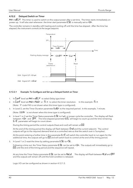
4.12.2 Delayed Switch on Timer<br />
P41 = DELY. This timer is used <strong>to</strong> switch on <strong>the</strong> output power after a set time. The timer starts immediately on<br />
power-up. It will also start whenever <strong>the</strong> timer start parameter t.St is manually set <strong>to</strong> rUn.<br />
The controller rema<strong>in</strong>s <strong>in</strong> standby with heat<strong>in</strong>g and cool<strong>in</strong>g off until <strong>the</strong> time has elapsed. After <strong>the</strong> time has<br />
elapsed, <strong>the</strong> <strong>in</strong>strument controls at <strong>the</strong> target setpo<strong>in</strong>t.<br />
Temperature<br />
SP1<br />
Timer Duration<br />
t.dUr<br />
Time<br />
Flash<strong>in</strong>g display message<br />
rUn/OFF<br />
End<br />
Power<br />
switched on<br />
Reset<br />
RUN Digital O/P = t.run<br />
END Digital O/P = t.End<br />
4.12.2.1 Example: To Configure and Set up a Delayed Switch on Timer<br />
1. In Conf level set P41 = DELY <strong>to</strong> select Delay type timer<br />
2. In Conf level set P42 = HoUr or N<strong>in</strong> <strong>to</strong> select <strong>the</strong> timer resolution. In this example N<strong>in</strong><br />
(Note: ‘P’ code P43 is not shown when this timer type is configured).<br />
3. In Level 2, set <strong>the</strong> Timer Duration parameter t.dUr <strong>to</strong> <strong>the</strong> required period. In this example, 1 m<strong>in</strong>ute.<br />
(Note: t.tHr is not shown when this timer type is configured).<br />
4. In level 1 or 2 set <strong>the</strong> Timer Status parameter t.St <strong>to</strong> run, or power cycle <strong>the</strong> controller. The display will flash<br />
between rUn and OFF. The time elapsed parameter t.EL will beg<strong>in</strong> <strong>to</strong> count up and <strong>the</strong> time rema<strong>in</strong><strong>in</strong>g<br />
t.rE parameter will beg<strong>in</strong> <strong>to</strong> count down.<br />
Dur<strong>in</strong>g <strong>the</strong> tim<strong>in</strong>g period <strong>the</strong> control outputs (heat and cool) will rema<strong>in</strong> at 0.0.<br />
At <strong>the</strong> end of <strong>the</strong> tim<strong>in</strong>g period <strong>the</strong> display will flash between End and <strong>the</strong> current setpo<strong>in</strong>t. The control<br />
outputs will go <strong>to</strong> <strong>the</strong> required demand level at a controlled rate so that <strong>the</strong> switch over is ‘bumpless’.<br />
At this po<strong>in</strong>t enter<strong>in</strong>g a fur<strong>the</strong>r time <strong>in</strong> <strong>the</strong> parameter t.rE will switch <strong>the</strong> controller back <strong>to</strong> run aga<strong>in</strong> for <strong>the</strong><br />
additional time, <strong>the</strong> outputs will go <strong>to</strong> 0.0 and will switch back <strong>to</strong> control at <strong>the</strong> end of <strong>the</strong> tim<strong>in</strong>g period.<br />
5. In Level 1 or 2 reset <strong>the</strong> timer by sett<strong>in</strong>g parameter t.St <strong>to</strong> rst.<br />
Follow<strong>in</strong>g a time out, <strong>the</strong> Timer Status parameter t.St can be set <strong>to</strong> rUn. The outputs will immediately go <strong>to</strong><br />
0.0 until <strong>the</strong> end of <strong>the</strong> tim<strong>in</strong>g period and <strong>the</strong> sequence will repeat.<br />
At any time <strong>the</strong> Timer Status parameter t.St can be set <strong>to</strong> HoLd. The display will flash between HLd and OFF<br />
and <strong>the</strong> outputs will rema<strong>in</strong> off until <strong>the</strong> hold condition is released.<br />
Logic I/O can be configured as shown <strong>in</strong> section 4.12.1.3.<br />
40 Part No HA031260 Issue 1 May -12