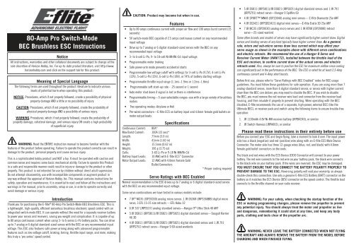
80-Amp Pro Switch-Mode BEC Brushless ESC Instructions - E-flite
80-Amp Pro Switch-Mode BEC Brushless ESC Instructions - E-flite
80-Amp Pro Switch-Mode BEC Brushless ESC Instructions - E-flite

You also want an ePaper? Increase the reach of your titles
YUMPU automatically turns print PDFs into web optimized ePapers that Google loves.
<strong>80</strong>-<strong>Amp</strong> <strong>Pro</strong> <strong>Switch</strong>-<strong>Mode</strong><br />
<strong>BEC</strong> <strong>Brushless</strong> <strong>ESC</strong> <strong>Instructions</strong><br />
Notice<br />
All instructions, warranties and other collateral documents are subject to change at the<br />
sole discretion of Horizon Hobby, Inc. For up-to-date product literature, visit http://www.<br />
horizonhobby.com and click on the support tab for this product.<br />
Meaning of Special Language<br />
The following terms are used throughout the product literature to indicate various<br />
levels of potential harm when operating this product:<br />
NOTICE: <strong>Pro</strong>cedures, which if not properly followed, create a possibility of physical<br />
property damage AND a little or no possibility of injury.<br />
CAUTION: <strong>Pro</strong>cedures, which if not properly followed, create the probability of<br />
physical property damage AND a possibility of serious injury.<br />
WARNING: <strong>Pro</strong>cedures, which if not properly followed, create the probability of<br />
property damage, collateral damage, and serious injury OR create a high probability<br />
of superficial injury.<br />
WARNING: Read the ENTIRE instruction manual to become familiar with the<br />
features of the product before operating. Failure to operate the product correctly can result in<br />
damage to the product, personal property and cause serious injury.<br />
This is a sophisticated hobby product and NOT a toy. It must be operated with caution and<br />
common sense and requires some basic mechanical ability. Failure to operate this <strong>Pro</strong>duct<br />
in a safe and responsible manner could result in injury or damage to the product or other<br />
property. This product is not intended for use by children without direct adult supervision.<br />
Do not attempt disassembly, use with incompatible components or augment product in<br />
any way without the approval of Horizon Hobby, Inc. This manual contains instructions for<br />
safety, operation and maintenance. It is essential to read and follow all the instructions and<br />
warnings in the manual, prior to assembly, setup or use, in order to operate correctly and<br />
avoid damage or serious injury.<br />
Introduction<br />
Thank you for purchasing the E-<strong>flite</strong> ® <strong>80</strong>-<strong>Amp</strong> <strong>Pro</strong> <strong>Switch</strong>-<strong>Mode</strong> <strong>BEC</strong> <strong>Brushless</strong> <strong>ESC</strong>. This is<br />
a lightweight, high-quality, efficient sensorless brushless electronic speed control with an<br />
integrated switch-mode <strong>BEC</strong>. It can operate without the need for a separate receiver battery<br />
to power your servos and receivers, saving you weight and complication. It is capable of up<br />
to <strong>80</strong> amps continuous current when using 3- to 6-series Li-Po battery packs. You can drive<br />
up to 7 analog or 6 digital standard-sized servos with the <strong>BEC</strong> on any recommended input<br />
voltage. This <strong>ESC</strong> also features safe power arming along with advanced programmable<br />
features such as low voltage cutoff, braking, timing, throttle input range, and more, making<br />
this truly a ‘pro series’ speed control.<br />
CAUTION: <strong>Pro</strong>duct may become hot when in use.<br />
Features<br />
• Up to <strong>80</strong> amps continuous current with proper air flow and 100 amps burst current (15<br />
seconds)<br />
• 5V switch-mode <strong>BEC</strong> capable of 2.5 amps continuous current on any recommended<br />
input voltage<br />
• Drive up to 7 analog or 6 digital standard-sized servos with the <strong>BEC</strong> on any<br />
recommended input voltage<br />
• 3- to 6-cell Li-Po, 9- to 18-cell Ni-MH/Ni-Cd input voltage<br />
• <strong>Pro</strong>grammable motor braking<br />
• Safe power-arm mode prevents accidental starts<br />
• <strong>Pro</strong>grammable low voltage cutoff with settings for 3-cell Li-Po (9.2V), 4-cell Li-Po<br />
(12V), 5-cell Li-Po (15V), 6-cell Li-Po (18V), or 74% of battery starting voltage<br />
• <strong>Pro</strong>grammable throttle input range (1.1ms–1.9ms or 1.2ms–1.8ms)<br />
• <strong>Pro</strong>grammable soft start-up rate - .25 second or 1 second<br />
• Auto motor shut down if signal is lost or there is interference<br />
• <strong>Pro</strong>grammable timing—5 user-selectable ranges–use with a large variety of brushless<br />
motors<br />
• Two operating modes–Airplane or Heli<br />
• Pre-wired connectors—E-<strong>flite</strong> EC5 on battery input and 4.0mm female gold bullets on<br />
motor output leads<br />
Specifications<br />
Continuous Current: <strong>80</strong>A*<br />
Max Burst Current: 100A (15 sec)*<br />
Length:<br />
77mm (3.0 in)<br />
Width:<br />
41mm (1.60 in)<br />
Height:<br />
15.5mm (0.62 in)<br />
Weight:<br />
106 g (3.75 oz)<br />
Cells:<br />
3-6S Li-Po or 9-18 Ni-MH/Ni-Cd<br />
Battery Input Leads: 10 AWG with E-<strong>flite</strong> EC5 Connector<br />
Motor Output Leads: 12 AWG with 4.0mm Female Gold<br />
Bullet Connectors<br />
* <strong>Pro</strong>per cooling required<br />
Servo Ratings with <strong>BEC</strong> Enabled<br />
Normal recommendation is the <strong>ESC</strong> drives up to 7 analog or 6 digital standard-sized servos<br />
with the <strong>BEC</strong> on any recommended input voltage.<br />
Some servo combinations we have tested in various models include:<br />
• 7 JR ® MC35 (JSP20030) analog micro servos ,1 JR DS368 (JRPS368BB) digital micro<br />
servo, 3 EFL 15-25 size retracts —EFL Habu 32<br />
• 6 JR 537 (JRPS537) analog standard servos—Hangar 9 ® Ultra Stick 40 ARF<br />
• 5 JR DS811 (JRPS811)/JR DS821 (JRPS821) digital standard servos—Seagull Harrier<br />
46 3D<br />
• 4 JR DS811 (JRPS811)/JR DS821 (JRPS821) digital standard servos and 1 JR 791<br />
(JRPS791) retract servo—Hangar 9 60-sized warbirds<br />
• 5 JR DS811 (JRPS811)/JR DS821 (JRPS821) digital standard servos and 1 JR 791<br />
(JRPS791) retract servo—Hangar 9 Spitfire 60<br />
• 4 JR SPORT MN48 (JSP20040) analog mini servos— E-<strong>flite</strong> Diamante 25e ARF<br />
• 4 JR DS3421 (JRPSDS3421) digital mini servos—E-<strong>flite</strong> Eratix 3D 25e ARF<br />
• 7 JR MC35 (JSP20030) analog micro servos and 1 JR RT88 (JSP200<strong>80</strong>) retract<br />
servo—25-sized warbird<br />
Some other brands and models of servos may have significantly higher current draw. Digital<br />
servos and binding servos of any kind typically have higher current draw. As a general<br />
rule, micro and sub-micro servos draw less current which may affect your<br />
servo usage as shown in the examples above with different servo combinations<br />
and electric retracts. We recommend the use of a Hangar 9 Servo and<br />
Receiver Current Meter (HAN172), installed between the throttle lead of the<br />
<strong>ESC</strong> and receiver, to confirm current draw of the actual servos and electric<br />
retracts used. Also, always be sure to position the <strong>ESC</strong> for maximum airflow since cooling<br />
can significantly aid in the performance of the <strong>BEC</strong>. The <strong>ESC</strong> is rated for at least 2.5-<strong>Amp</strong><br />
continuous current and 4-<strong>Amp</strong> short bursts.<br />
Before first use, please refer to “Servo Ratings with <strong>BEC</strong> Enabled” notes for <strong>BEC</strong> usage<br />
guidelines. You must follow these guidelines for safe operation. If you are using more than 7<br />
analog standard servos, more than 6 digital standard servos, or servos with higher current<br />
draw than the <strong>BEC</strong> can deliver, you may need to disable the <strong>BEC</strong>. If you wish to disable<br />
the <strong>BEC</strong>, you must remove the red receiver wire lead and connector from the receiver lead<br />
housing, and then insulate it properly to prevent shorting. When operating with the <strong>BEC</strong><br />
disabled, E-<strong>flite</strong> recommends the use of a separate, high-power, external <strong>BEC</strong> (like the<br />
Ultimate <strong>BEC</strong>), or receiver pack and switch using the following items to ensure trouble-free<br />
operation:<br />
1. JR 1100mAh 4.8V Ni-MH receiver battery (JRPB4240), or similar<br />
2. JR <strong>Switch</strong> Harness (JRPA003), or similar<br />
Please read these instructions in their entirety before use<br />
Before you connect your <strong>ESC</strong> and begin flying, take a moment to look it over. The input power<br />
side has a black (negative) and red (positive) wire along with an E-<strong>flite</strong> EC5 Male Device<br />
Connector. The motor side has three 12-gauge wires (blue, red, and black) with 4.0mm<br />
female gold bullet connectors on the ends.<br />
The black and red wires with the EC5 Device (DEV) Connector will connect to your power<br />
battery. The red wire connects to the red wire on your battery pack, the black wire connects<br />
to the black wire on your battery pack. If the wires are reversed, the <strong>ESC</strong> may be damaged.<br />
YOU MUST ENSURE THAT YOU CONNECT THE BATTERY POLARITY PROPERLY TO<br />
PREVENT DAMAGE TO THE <strong>ESC</strong>. Reversing polarity will void your warranty, so always<br />
double-check this connection. Use only a genuine E-<strong>flite</strong> EC5 Battery (BATT) connector on the<br />
battery so it matches the EC5 Device (DEV) connector on the speed control. The throttle lead<br />
connects to the throttle channel on your radio receiver.<br />
WARNING: For your safety, when checking the startup function of the<br />
<strong>ESC</strong> or making programming changes, please remove the propeller to prevent<br />
any potential injury. You should always treat the motor and propeller as live<br />
and dangerous, remembering it could start at any time, and keep any body<br />
parts, clothing and tools clear of the propeller arc.<br />
WARNING: NEVER LEAVE THE BATTERY CONNECTED WHEN NOT FLYING<br />
THE AIRCRAFT AND ALWAYS REMOVE THE BATTERY FROM THE MODEL BEFORE<br />
CHARGING AND WHEN FINISHED FLYING.
When flying in hot weather, we recommend checking on the condition of the <strong>ESC</strong>, battery,<br />
and motor after each flight. You may want to consider letting the electronic components<br />
cool to near ambient temperature between flights. We also recommend throttle management<br />
when running near maximum levels of current draw during extreme conditions. It is not<br />
recommended you fly an entire flight at full throttle. If this is done, it is possible to cause<br />
permanent damage to your motor, battery, and <strong>ESC</strong>.<br />
Using the <strong>80</strong>-<strong>Amp</strong> <strong>Pro</strong> <strong>Switch</strong>-mode <strong>BEC</strong> <strong>Brushless</strong> Controller<br />
This controller is very simple to use, and for safety, will not arm the motor until the throttle<br />
stick has been held in the Idle/Off position for more than 1 second. The controller will<br />
indicate the soft cutoff voltage setting every time you plug the battery in by first emitting<br />
a low, long tone, to indicate startup. Depending on the selected cutoff voltage (default is<br />
74%), you will then hear the respective number of medium length mid tones to indicate the<br />
cell count or a musical tone for the 74% cutoff, helping you to confirm the setting before<br />
every flight. <strong>Pro</strong>per air cooling is required during flights so the <strong>ESC</strong> should be place in an<br />
area where air flows over the controller. We recommend you change your cutoff<br />
voltage to match the cell count of your battery.<br />
Connecting the <strong>ESC</strong> to the Motor<br />
The three wires from your motor connect to the three female gold bullet connectors on the<br />
<strong>ESC</strong>. The order of connection to the motor is not important; you can plug any motor wire into<br />
any connector. When you test the system, the motor runs backwards, you can simply unplug<br />
and switch any two of the motor wire plugs connected to the <strong>ESC</strong>.<br />
Mounting the <strong>ESC</strong><br />
Choose a location that has good airflow and offers good protection. Do not cover the the<br />
side with the flat heat shield with hook and loop or tape as this will greatly reduce its<br />
effectiveness. Mount the <strong>ESC</strong> with a combination of hook and loop, two-sided foam tape,<br />
and/or tie wraps.<br />
Starting Your Power System<br />
1. Turn on your transmitter and ensure the position of the throttle stick is set to Idle/Off.<br />
2. Plug the battery pack into the controller. You will hear 1 low long tone to indicate<br />
startup, then the respective number of medium-length mid tones to indicate the cell<br />
count or a musical tone for the 74% cutoff, followed by 3 rising tones to indicate the<br />
controller is armed.<br />
3. When you move the throttle stick upward, the motor will run. If you continue to move<br />
the throttle stick upward to the full throttle (high position), the motor will run faster. If<br />
you lower the throttle stick below the start-up position, the motor will stop running.<br />
4. Check servo motion as part of your preflight check. It is very important to make sure<br />
linkages are free-moving with no binding.<br />
Remember, when in the programming mode:<br />
Full Throttle = Stick Up<br />
Idle = Stick Down<br />
The default settings (from the package) for your E-<strong>flite</strong> <strong>80</strong>-<strong>Amp</strong> <strong>Pro</strong> <strong>ESC</strong> are as follows:<br />
• Voltage cutoff set at 74%*<br />
• Brake set to Off<br />
• Timing set at 15 degrees<br />
• Throttle Input Range set at 1.2ms to 1.8ms<br />
• Start-up Rate (Acceleration Delay) set at 0.25 seconds<br />
• PWM Frequency set at 8KHz<br />
• Operating <strong>Mode</strong> set to normal (airplane)<br />
* Note: We recommend changing the cutoff voltage to match<br />
the cell count of your battery.<br />
Entering the <strong>Pro</strong>gramming <strong>Mode</strong><br />
1. With the battery disconnected from the controller, and the transmitter turned on, first<br />
move the throttle stick to full throttle (>1.7ms) position. Leave it in this position and<br />
then connect the battery to the controller.<br />
2. Wait for 5 seconds, and the <strong>ESC</strong> will give two sets of fast ringing tones to indicate you<br />
have successfully entered the programming mode.<br />
3. Once you hear these tones, move the stick to center (between 1.4 and 1.7ms) for 5<br />
seconds, and the controller will beep 1 time, indicating you are now in Menu 1.<br />
4. The controller will now wait 5 seconds for you to make your selection; your programming<br />
options are either full throttle (>1.7ms) or idle (1.7ms) position. You will have 5<br />
seconds to make your selection.<br />
7. If you want to advance to the next menu, allow the programming to skip to the next<br />
menu after the 5 seconds have expired.<br />
<strong>Pro</strong>gramming Menu 1 – Voltage Cutoff<br />
Use this option to set the voltage at which the controller will shut down the motor to prevent<br />
damage to your battery when it reaches the cutoff voltage. You will know your battery pack<br />
has reached auto cutoff when you hear the motor “pulse” repeatedly. We recommend you<br />
change your cutoff voltage to match the cell count of your battery.<br />
1. Move the throttle stick to full throttle (>1.7ms) position to make changes to the<br />
voltage cutoff programming.<br />
a. To select 3-cell low voltage cutoff – You will hear 3 short beeps. Move the<br />
throttle stick to center (between 1.4 and 1.6ms). The controller will beep 2 times,<br />
indicating you have set the program selection or leave in full throttle for 5 seconds<br />
to advance to the next selection.<br />
b. To select 4-cell low voltage cutoff – You will hear 4 short beeps. Move the<br />
throttle stick to center (between 1.4 and 1.6ms). The controller will beep 2 times,<br />
indicating you have set the program selection or leave in full throttle for 5 seconds<br />
to advance to the next selection.<br />
c. To select 5-cell low voltage cutoff – You will hear 5 shortbeeps. Move the throttle<br />
stick to center (between 1.4 and 1.6ms). The controller will beep 2 times,<br />
indicating you have set the program selection or leave in full throttle for 5 seconds<br />
to advance to the next selection.<br />
d. To select 6-cell low voltage cutoff – You will hear 6 short beeps. Move the<br />
throttle stick to center (between 1.4 and 1.6ms). The controller will beep 2 times,<br />
indicating you have set the program selection or leave in full throttle for 5 seconds<br />
to advance to the next selection.<br />
e. To select 74% cutoff – You will hear 7 short beeps. Move the throttle stick to center<br />
(between 1.4 and 1.6ms). The controller will beep 2 times, indicating you have set<br />
the program selection or leave in full throttle for 5 seconds to advance to the first<br />
selection again.<br />
IMPORTANT NOTE ABOUT 74% CUTOFF: Your battery pack should be fully charged in this<br />
voltage cutoff setting because it bases the cutoff on the start up voltage of the pack. This<br />
option will activate the soft cutoff at 74% of startup voltage or 9.2V, whichever is lower.<br />
For example, if your pack measures 16.8 volts at startup, then the soft cut will occur at<br />
12.4 volts. The 74% cutoff option will check the startup voltage every time you plug the<br />
battery into the controller, so beware of using partially charged packs, as the system cannot<br />
protect your Li-Po batteries if you are using the 74% cutoff and connect a partially charged<br />
pack. You will know your battery pack has reached soft auto cutoff when you hear the motor<br />
“pulse” repeatedly. We recommend you land your model as soon as you hear the motor<br />
pulse (indicating the pack voltage has dropped to the cutoff voltage level) to prevent overdischarge<br />
of the Li-Po battery pack, and to prevent sudden power loss.<br />
<strong>Pro</strong>gramming Menu 2 – Brake Type<br />
The default setting is Brake Off. This option gives you the choice to have the <strong>ESC</strong> stop the<br />
propeller during flight (Brake On) or allow it to windmill (Brake Off). Use the Brake On options<br />
for folding propellers.<br />
1. Move the stick to center (between 1.4 and 1.6ms) for 5 seconds, and the controller will<br />
beep 2 times, indicating you are now in Menu 2.<br />
2. Move the throttle stick to full throttle (>1.7ms) position to make changes to the Brake<br />
Type programming.<br />
a. To select No Brake/Brake Off – You will hear 1 short beep. Move the throttle stick<br />
to center (between 1.4 and 1.6ms). The controller will beep 2 times, indicating you<br />
have set the program selection or leave in full throttle for 5 seconds to advance to<br />
the next selection.<br />
b. To select Soft Brake – You will hear 2 short beeps. Move the throttle stick to center<br />
(between 1.4 and 1.6ms). The controller will beep 2 times, indicating you have set<br />
the program selection or leave in full throttle for 5 seconds to advance to the next<br />
selection.<br />
c. To select Medium Brake – You will hear 3 short beeps. Move the throttle stick to<br />
center (between 1.4 and 1.6ms). The controller will beep 2 times, indicating you<br />
have set the program selection or leave in full throttle for 5 seconds to advance to<br />
the next selection.<br />
d. To select Hard Brake – You will hear 4 short beeps. Move the throttle stick to center<br />
(between 1.4 and 1.6ms). The controller will beep 2 times, indicating you have set<br />
the program selection or leave in full throttle for 5 seconds to advance to the first<br />
selection again.<br />
<strong>Pro</strong>gramming Menu 3 – Timing<br />
The default setting is 15 degrees. As a general rule, lower pole count motors use lower timing<br />
and higher pole count motors use higher timing. Please refer to your motor instructions and<br />
specifications for an indication of the number of poles.<br />
Low Timing Advance<br />
Timing Degrees – 5 & 10<br />
Motor Poles – 2 to 4<br />
Expected Performance – Good balance of power and efficiency<br />
Motor Poles – 6 or more<br />
Expected Performance – Best efficiency and run time (lowest power)<br />
Standard Timing Advance<br />
Timing Degrees – 15 & 20<br />
Motor Poles – 6 to 12<br />
Expected Performance – Good balance of power and efficiency<br />
Motor Poles – 14 or more<br />
Expected Performance – Best efficiency and run time (lowest power)<br />
High Timing Advance<br />
Timing Degrees – 25<br />
Motor Poles – 12<br />
Expected Performance – Highest power, less efficiency
Motor Poles – 14 or more<br />
Expected Performance – Good balance of power and efficiency<br />
1. Move the stick to center (between 1.4 and 1.6ms) for 5 seconds, and the controller will<br />
beep 3 times, indicating you are now in Menu 3.<br />
2. Move the throttle stick to full throttle (>1.7ms) position to make changes to the Timing<br />
programming.<br />
a. To select 5 Degrees – You will hear 1 short beep. Move the throttle stick to center<br />
(between 1.4 and 1.6ms). The controller will beep 2 times, indicating you have set<br />
the program selection or leave in full throttle for 5 seconds to advance to the next<br />
selection.<br />
b. To select 10 Degrees – You will hear 2 short beeps. Move the throttle stick to center<br />
(between 1.4 and 1.6ms). The controller will beep 2 times, indicating you have set<br />
the program selection or leave in full throttle for 5 seconds to advance to the next<br />
selection.<br />
c. To select 15 Degrees – You will hear 3 short beeps. Move the throttle stick to center<br />
(between 1.4 and 1.6ms). The controller will beep 2 times, indicating you have set<br />
the program selection or leave in full throttle for 5 seconds to advance to the next<br />
selection.<br />
d. To select 20 Degrees – You will hear 4 short beeps. Move the throttle stick to center<br />
(between 1.4 and 1.6ms). The controller will beep 2 times, indicating you have set<br />
the program selection or leave in full throttle for 5 seconds to advance to the next<br />
selection.<br />
e. To select 25 Degrees – You will hear 5 short beeps. Move the throttle stick to center<br />
(between 1.4 and 1.6ms). The controller will beep 2 times, indicating you have set<br />
the program selection or leave in full throttle for 5 seconds to advance to the first<br />
selection again.<br />
<strong>Pro</strong>gramming Menu 4 – Throttle Input Range (PWM)<br />
The default setting is 1.2ms to 1.8ms and should work with most radio systems. This option<br />
allows for proper throttle input with many different radio systems. However, some radios<br />
have a wider output range, and may give a more linear response with the 1.1ms to 1.9ms<br />
range. If you feel there is too much “dead” area in the stick movement near full throttle, try<br />
adjusting the end points in your radio, or change to the wider input range. Be aware that if<br />
these settings are not correct, it may be impossible to arm the controller.<br />
1. Move the stick to center (between 1.4 and 1.6ms) for 5 seconds, and the controller will<br />
beep 4 times, indicating you are now in Menu 4.<br />
2. Move the throttle stick to full throttle (>1.7ms) position to make changes to the<br />
Throttle Input Range programming.<br />
a. To select 1.2ms to 1.8ms – You will hear 1 short beep. Move the throttle stick to<br />
center (between 1.4 and 1.6ms). The controller will beep 2 times, indicating you<br />
have set the program selection or leave in full throttle for 5 seconds to advance to<br />
the next selection.<br />
b. To select 1.1ms to 1.9ms – You will hear 2 short beeps. Move the throttle stick to<br />
center (between 1.4 and 1.6ms). The controller will beep 2 times, indicating you<br />
have set the program selection or leave in full throttle for 5 seconds to advance to<br />
the first selection again.<br />
<strong>Pro</strong>gramming Menu 5 – Start-Up Rate<br />
The default setting is 0.25 seconds. The start-up rate is the time it takes to reach maximum<br />
motor speed. Changing the setting to 1 second can be useful with power-fragile gear boxes.<br />
1. Move the stick to center (between 1.4 and 1.6ms) for 5 seconds, and the controller will<br />
beep 5 times, indicating you are now in Menu 3.<br />
2. Move the throttle stick to full throttle (>1.7ms) position to make changes to the Startup<br />
Rate programming.<br />
a. To select .25 second – You will hear 1 short beep. Move the throttle stick to center<br />
(between 1.4 and 1.6ms). The controller will beep 2 times, indicating you have set<br />
the program selection or leave in full throttle for 5 seconds to advance to the next<br />
selection.<br />
b. To select 1 second – You will hear 2 short beeps. Move the throttle stick to center<br />
(between 1.4 and 1.6ms). The controller will beep 2 times, indicating you have set<br />
the program selection or leave in full throttle for 5 seconds to advance to the first<br />
selection again.<br />
<strong>Pro</strong>gramming Menu 6 – PWM <strong>Switch</strong>ing Frequency<br />
The default setting is 8KHz, which should be acceptable for most motors. If you have a<br />
low or very low inductance motor and know you need to use a higher PWM Frequency (refer<br />
to the manual included with the motor), then you can change the setting. Otherwise, we<br />
recommend leaving the default setting.<br />
1. Move the stick to center (between 1.4 and 1.6ms) for 5 seconds, and the controller will<br />
beep 6 times, indicating you are now in Menu 6.<br />
2. Move the throttle stick to full throttle (>1.7ms) position to make changes to the PWM<br />
<strong>Switch</strong>ing Frequency programming.<br />
a. To select 8KHz PWM Frequency – You will hear 1 short beep. Move the throttle stick<br />
to center (between 1.4 and 1.6ms). The controller will beep 2 times, indicating you<br />
have set the program selection or leave in full throttle for 5 seconds to advance to<br />
the next selection.<br />
b. To select 16KHz PWM Frequency – You will hear 2 short beeps. Move the throttle<br />
stick to center (between 1.4 and 1.6ms). The controller will beep 2 times,<br />
indicating you have set the program selection or leave in full throttle for 5 seconds<br />
to advance to the next selection.<br />
c. To select 32KHz PWM Frequency – You will hear 3 short beeps. Move the throttle<br />
stick to center (between 1.4 and 1.6ms). The controller will beep 2 times,<br />
indicating you have set the program selection or leave in full throttle for 5 seconds<br />
to advance to the first selection again.<br />
<strong>Pro</strong>gramming Menu 7 – Operating <strong>Mode</strong><br />
The default setting is set to Normal (airplane) <strong>Mode</strong>, which is limited to a start-up rate of<br />
0.25 or 1 second. Alternatively, the Heli <strong>Mode</strong> can be selected which reduces the start-up<br />
rate to 5 seconds for the first start-up and any start-up after the motor/<strong>ESC</strong> has been<br />
stopped for more than 5 seconds. This helps to prevent damaging the motor, gears or any<br />
other components from an abrupt start-up when none of the parts are moving. Any time<br />
the motor/<strong>ESC</strong> has been stopped for less than 5 seconds in Heli <strong>Mode</strong>, the start-up will<br />
be immediate. This allows power to be applied immediately, such as when aborting an<br />
auto-rotation attempt or for any other reason, to help prevent a crash. Remember, you must<br />
wait more than 5 seconds after stopping the motor/<strong>ESC</strong> in order for the 5-second start-up to<br />
occur again.<br />
1. Move the stick to center (between 1.4 and 1.6ms) for 5 seconds, and the controller will<br />
beep 7 times, indicating you are now in Menu 7.<br />
2. Move the throttle stick to full throttle (>1.7ms) position to make changes to the<br />
Operating <strong>Mode</strong> programming.<br />
a. To select Normal <strong>Mode</strong> – You will hear 1 short beep. Move the throttle stick to<br />
center (between 1.4 and 1.6ms). The controller will beep 2 times, indicating you<br />
have set the program selection or leave in full throttle for 5 seconds to advance to<br />
the next selection.<br />
b. To select Heli <strong>Mode</strong> – You will hear 2 short beeps. Move the throttle stick to center<br />
(between 1.4 and 1.6ms). The controller will beep 2 times, indicating you have set<br />
the program selection or leave in full throttle for 5 seconds to advance to the first<br />
selection again.<br />
Troubleshooting<br />
The controller will beep more quietly than normal if the input voltage is below the cutoff<br />
voltage when the battery is connected. Check the voltage of the battery pack to see if it is<br />
correct (charged), or the programmed cutoff setting if the input voltage is set incorrectly for<br />
the voltage of the pack being used.<br />
If you have trouble arming the controller (and the throttle trim has been set to minimum),<br />
enter the programming mode and try changing the setting to 1.1ms–1.9ms in <strong>Pro</strong>gramming<br />
Menu 4 to see if it helps correct the problem. If it is a computer radio, you may alternatively<br />
increase high and low throttle ATV (endpoint) percentages.<br />
Note: Increasing the high ATV will not have a consequence on arming issues, only low ATV.<br />
Some transmitters, including all Futaba transmitters, will require the throttle channel to be<br />
“reversed” for proper operation.<br />
Warranty and Repair Policy<br />
Exclusive Warranty- Horizon Hobby, Inc., (Horizon) warranties that the <strong>Pro</strong>ducts purchased<br />
(the “<strong>Pro</strong>duct”) will be free from defects in materials and workmanship for a period of 1 year<br />
from the date of purchase by the Purchaser.<br />
1 Year Limited Warranty<br />
Horizon reserves the right to change or modify this warranty without notice<br />
and disclaims all other warranties, express or implied.<br />
(a) This warranty is limited to the original Purchaser (“Purchaser”) and is not transferable.<br />
REPAIR OR REPLACEMENT AS PROVIDED UNDER THIS WARRANTY IS THE EXCLUSIVE REMEDY<br />
OF THE PURCHASER. This warranty covers only those <strong>Pro</strong>ducts purchased from an authorized<br />
Horizon dealer. Third party transactions are not covered by this warranty. <strong>Pro</strong>of of purchase is<br />
required for all warranty claims.<br />
(b) Limitations- HORIZON MAKES NO WARRANTY OR REPRESENTATION, EXPRESS OR IMPLIED,<br />
ABOUT NON-INFRINGEMENT, MERCHANTABILITY OR FITNESS FOR A PARTICULAR PURPOSE OF<br />
THE PRODUCT. THE PURCHASER ACKNOWLEDGES THAT THEY ALONE HAVE DETERMINED THAT<br />
THE PRODUCT WILL SUITABLY MEET THE REQUIREMENTS OF THE PURCHASER’S INTENDED<br />
USE.<br />
(c) Purchaser Remedy- Horizon’s sole obligation hereunder shall be that Horizon will, at its<br />
option, (i) repair or (ii) replace, any <strong>Pro</strong>duct determined by Horizon to be defective. In the<br />
event of a defect, these are the Purchaser’s exclusive remedies. Horizon reserves the right to<br />
inspect any and all equipment involved in a warranty claim. Repair or replacement decisions<br />
are at the sole discretion of Horizon. This warranty does not cover cosmetic damage or<br />
damage due to acts of God, accident, misuse, abuse, negligence, commercial use, or<br />
modification of or to any part of the <strong>Pro</strong>duct. This warranty does not cover damage due to<br />
improper installation, operation, maintenance, or attempted repair by anyone other than<br />
Horizon. Return of any <strong>Pro</strong>duct by Purchaser must be approved in writing by Horizon before<br />
shipment.<br />
Damage Limits<br />
HORIZON SHALL NOT BE LIABLE FOR SPECIAL, INDIRECT OR CONSEQUENTIAL DAMAGES,<br />
LOSS OF PROFITS OR PRODUCTION OR COMMERCIAL LOSS IN ANY WAY CONNECTED WITH<br />
THE PRODUCT, WHETHER SUCH CLAIM IS BASED IN CONTRACT, WARRANTY, NEGLIGENCE,<br />
OR STRICT LIABILITY. Further, in no event shall the liability of Horizon exceed the individual<br />
price of the <strong>Pro</strong>duct on which liability is asserted. As Horizon has no control over use, setup,<br />
final assembly, modification or misuse, no liability shall be assumed nor accepted for<br />
any resulting damage or injury. By the act of use, setup or assembly, the user accepts all<br />
resulting liability.
If you as the Purchaser or user are not prepared to accept the liability associated with the<br />
use of this <strong>Pro</strong>duct, you are advised to return this <strong>Pro</strong>duct immediately in new and unused<br />
condition to the place of purchase.<br />
Law: These Terms are governed by Illinois law (without regard to conflict of law principals).<br />
Warranty Services<br />
Questions, Assistance, and Repairs<br />
Your local hobby store and/or place of purchase cannot provide warranty support or repair.<br />
Once assembly, setup or use of the <strong>Pro</strong>duct has been started, you must contact Horizon<br />
directly. This will enable Horizon to better answer your questions and service you in the event<br />
that you may need any assistance. For questions or assistance, please direct your email<br />
to productsupport@horizonhobby.com, or call 877.504.0233 toll free to speak to a <strong>Pro</strong>duct<br />
Support representative. You may also find information on our website at www.horizonhobby.<br />
com.<br />
Inspection or Repairs<br />
If this <strong>Pro</strong>duct needs to be inspected or repaired, please use the Horizon Online Repair<br />
Request submission process found on our website or call Horizon to obtain a Return<br />
Merchandise Authorization (RMA) number. Pack the <strong>Pro</strong>duct securely using a shipping carton.<br />
Please note that original boxes may be included, but are not designed to withstand the<br />
rigors of shipping without additional protection. Ship via a carrier that provides tracking and<br />
insurance for lost or damaged parcels, as Horizon is not responsible for merchandise until it<br />
arrives and is accepted at our facility. An Online Repair Request is available at http://www.<br />
horizonhobby.com under the Repairs tab. If you do not have internet access, please contact<br />
Horizon <strong>Pro</strong>duct Support to obtain a RMA number along with instructions for submitting your<br />
product for repair. When calling Horizon, you will be asked to provide your complete name,<br />
street address, email address and phone number where you can be reached during business<br />
hours. When sending product into Horizon, please include your RMA number, a list of the<br />
included items, and a brief summary of the problem. A copy of your original sales receipt<br />
must be included for warranty consideration. Be sure your name, address, and RMA number<br />
are clearly written on the outside of the shipping carton.<br />
Notice: Do not ship batteries to Horizon. If you have any issue with a battery,<br />
please contact the appropriate Horizon <strong>Pro</strong>duct Support office.<br />
Warranty Inspection and Repairs<br />
To receive warranty service, you must include your original sales receipt<br />
verifying the proof-of-purchase date. <strong>Pro</strong>vided warranty conditions have been met,<br />
your <strong>Pro</strong>duct will be repaired or replaced free of charge. Repair or replacement decisions are<br />
at the sole discretion of Horizon.<br />
Non-Warranty Repairs<br />
Should your repair not be covered by warranty the repair will be completed<br />
and payment will be required without notification or estimate of the expense<br />
unless the expense exceeds 50% of the retail purchase cost. By submitting<br />
the item for repair you are agreeing to payment of the repair without notification. Repair<br />
estimates are available upon request. You must include this request with your repair. Nonwarranty<br />
repair estimates will be billed a minimum of ½ hour of labor. In addition you will be<br />
billed for return freight. Horizon accepts money orders and cashiers checks, as well as Visa,<br />
MasterCard, American Express, and Discover cards. By submitting any item to Horizon for<br />
inspection or repair, you are agreeing to Horizon’s Terms and Conditions found on our website<br />
under the Repairs tab.<br />
United States<br />
United Kingdom<br />
Germany<br />
France<br />
(Electronics and engines)<br />
Horizon Service Center<br />
4105 Fieldstone Rd<br />
Champaign, Illinois<br />
61822 USA<br />
productsupport@horizonhobby.com<br />
877-504-0233<br />
Online Repair Request visit:<br />
www.horizonhobby.com/repairs<br />
(All other products)<br />
Horizon <strong>Pro</strong>duct Support<br />
4105 Fieldstone Rd<br />
Champaign, Illinois<br />
61822 USA<br />
productsupport@horizonhobby.com<br />
877-504-0233<br />
Horizon Hobby Limited<br />
Units 1-4 Ployters Rd<br />
Staple Tye<br />
Harlow, Essex<br />
CM18 7NS<br />
United Kingdom<br />
sales@horizonhobby.co.uk<br />
+44 (0) 1279 641 097<br />
Horizon Technischer Service<br />
Hamburger Str. 10<br />
25335 Elmshorn<br />
Germany<br />
service@horizonhobby.de<br />
+49 4121 46199 66<br />
Horizon Hobby SAS<br />
14 Rue Gustave Eiffel<br />
Zone d’Activité du Réveil Matin<br />
91230 Montgeron<br />
infofrance@horizonhobby.com<br />
+33 (0) 1 60 47 44 70<br />
Compliance Information for the European Union<br />
<strong>Instructions</strong> for Disposal of WEEE by<br />
Users in the European Union<br />
This product must not be disposed of with other waste. Instead, it is the user’s responsibility<br />
to dispose of their waste equipment by handing it over to a designated collection point for<br />
the recycling of waste electrical and electronic equipment. The separate collection and<br />
recycling of your waste equipment at the time of disposal will help to conserve natural<br />
resources and ensure that it is recycled in a manner that protects human health and the<br />
environment. For more information about where you can drop off your waste equipment for<br />
recycling, please contact your local city office, your household waste disposal service or<br />
where you purchased the product.<br />
© 2010 Horizon Hobby, Inc.<br />
www.horizonhobby.com<br />
www.E-<strong>flite</strong>RC.com<br />
All marks are trademarks or registered trademarks of Horizon Hobby, Inc.<br />
Made in China<br />
Revised 12/10<br />
31542