k GALVANISCHER ISOLATOR GI 16 - Philippi
k GALVANISCHER ISOLATOR GI 16 - Philippi
k GALVANISCHER ISOLATOR GI 16 - Philippi

You also want an ePaper? Increase the reach of your titles
YUMPU automatically turns print PDFs into web optimized ePapers that Google loves.
k <strong>GALVANISCHER</strong> <strong>ISOLATOR</strong> <strong>GI</strong> <strong>16</strong><br />
ANWENDUNG<br />
Der galvanische Isolator wird zur Vermeidung galvanischer Ströme zwischen dem Rumpf und dem Landnetz installiert.<br />
Zwei jeweils antiparallel und in Reihe geschaltete Dioden erzeugen ein so hohes Sperrpotenzial, dass galvanische Ströme nicht mehr<br />
fließen können.<br />
Der galvanische Isolator ist auch für Yachten mit Kunststoffrumpf geeignet, um die Antriebseinheit vor galvanischer Korrosion, bedingt<br />
durch den Landanschluss, zu unterbinden.<br />
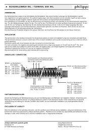
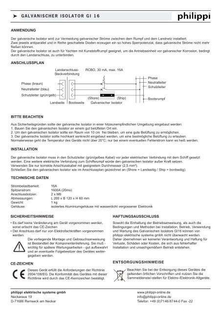
ANSCHLUSSPLAN<br />
Phase (braun)<br />
Neutralleiter (blau)<br />
Schutzleiter (grün/gelb)<br />
Landanschluss-<br />
Steckverbindung<br />
Landseite<br />
Bootsseite<br />
RCBO, 30 mA, max. <strong>16</strong>A<br />
(Shore) (Ship)<br />
Galvanischer Isolator<br />
Phase<br />
Neutralleiter<br />
Schutzleiter<br />
Bootsrumpf<br />
BITTE BEACHTEN<br />
Aus Sicherheitsgründen sollte der galvanische Isolator in einer hitzeunempfindlichen Umgebung eingebaut werden:<br />
1. Bauen Sie den galvanischen Isolator an einem gut belüfteten Ort ein.<br />
2. Um den galvanischen Isolator sollte ein Raum von 10 cm frei bleiben, um eine gute Belüftung zu ermöglichen.<br />
3. Der galvanische Isolator sollte hochkant senkrecht eingebaut werden, um eine bestmögliche Belüftung zu erlauben.<br />
Normalerweise geht die Temperatur des Geräts nicht über 20°C; nur bei einem eventuellen Fehlerstrom kann es heiß werden.<br />
INSTALLATION<br />
Der galvanische Isolator muss in den Schutzleiter (grün/gelbes Kabel) vor jeder elektrischen Verbindung mit dem Schiff gesetzt<br />
werden. Eine weitere elektrische Verbindung zum Schiffsrumpf würde den galvanischen Isolator außer Kraft setzen.<br />
Verwenden Sie nur korrekte Anschlusskabel mit geeignetem Durchmesser (2,5 mm²).<br />
Schließen Sie den galvanischen Isolator wie im Anschlussplan gezeichnet an (Shore = Landseitig / Ship = bordseitig).<br />
TECHNISCHE DATEN<br />
Strombelastbarkeit:<br />
Spitzenstrom:<br />
Anschlussbolzen:<br />
Abmessungen:<br />
Gewicht:<br />
Gehäuse:<br />
<strong>16</strong>A<br />
<strong>16</strong>00A (20ms)<br />
2 x M6<br />
L 200 x B 120 x H 60 mm<br />
1 kg<br />
isoliertes Aluminiumgehäuse mit wasserdicht vergossener Elektronik<br />
SICHERHEITSHINWEISE<br />
• Es darf keine Veränderung am Gerät vorgenommen werden,<br />
sonst erlischt das CE-Zeichen<br />
• Der Anschluss darf nur von Elektrofachkräften vorgenommen<br />
werden.<br />
Die vorliegende Montage und Gebrauchsanweisung<br />
ist Bestandteil der Komponentenlieferung. Sie muß -<br />
wichtig für spätere Wartungsarbeiten - gut aufbewahrt<br />
und an eventuelle Folgebesitzer des Gerätes weitergegeben<br />
werden.<br />
CE-ZEICHEN<br />
Dieses Gerät erfüllt die Anforderungen der Richtinie<br />
2004/108/EG. Die Konformität des Gerätes mit dieser<br />
Richtlinie wird durch das CE-Kennzeichen bestätigt.<br />
HAFTUNGSAUSSCHLUSS<br />
Sowohl die Einhaltung der Betriebsanweisung, als auch die<br />
Bedingungen und Methoden bei Installation, Betrieb, Verwendung<br />
und Wartung des Galvanischen Isolators <strong>GI</strong><strong>16</strong> können von<br />
philippi elektrische systeme gmbh nicht überwacht werden.<br />
Daher übernehmen wir keinerlei Verantwortung und Haftung für<br />
Verluste, Schäden oder Kosten, die sich aus fehlerhafter<br />
Installation und unsachgemäßem Betrieb entstehen.<br />
ENTSORGUNGSHINWEISE<br />
Beachten Sie bei der Entsorgung dieses Gerätes die<br />
geltenden örtlichen Vorschriften und nutzen Sie die<br />
Sammeldienste/-stellen für Elektro-/Elektronik-Altgeräte.<br />
philippi elektrische systeme gmbh<br />
www.philippi-online.de<br />
Neckaraue 19<br />
info@philippi-online.de<br />
D-7<strong>16</strong>86 Remseck am Neckar Telefon: +49 (0)7146/8744-0 Fax -22
k GALVANIC <strong>ISOLATOR</strong> <strong>GI</strong> <strong>16</strong><br />
APPLICATION<br />
To avoid galvanic currents between the hull and the shore power, a galvanic isolator can be used. Two anti - parallel diodes in the line<br />
produces a drop voltage, enough to avoid galvanic currents.<br />
It`s money well spend even for GRP hulls to avoid galvanic corrosion caused by the shore power connection to the propulsion!<br />
Easy installation: the earth wire has to be split near the shore power connection unit and the galvanic isolator has to be connected in<br />
between .<br />
CONNECTION<br />
Shore socket<br />
Live<br />
Neutral<br />
Earth<br />
Shore-side Boat-side<br />
RCBO, 30 mA, max <strong>16</strong>A<br />
(Shore) (Ship)<br />
Galvanic Isolator<br />
Live<br />
Neutral<br />
Earth<br />
Boat ground<br />
WARNING!<br />
For safety purposes, the product should be installed in a heat-resistant environment. Avoid the presence of e.g. chemicals,<br />
synthetic components, curtains or other textiles in the immediate vicinity of the product.<br />
1.Install the galvanic isolator in a well ventilated area.<br />
2.Keep a clear space of 10 cm around the product for ventilation.<br />
3.The galvanic isolator must be mounted with its length vertical to allow for maximum cooling. Under normal circumstances, the temperature<br />
increase of the heat sink is not more than 20°C. However the unit may become hot when conducting fault ground current.<br />
INSTALLATION<br />
The galvanic isolator must be wired into the green (safety) grounding conducting connection ahead of all grounding connections to<br />
the vessel such that no ground connections on the vessel bypass the galvanic isolator making it ineffective.<br />
1.Connections and safety features must be according to the locally applicable regulations.<br />
2.Use electric cables of the appropriate size.<br />
3.Wire the galvanic Isolator into the green (safety) grounding conducting connection as shown above<br />
(Shore = connection of the shore wire, Ship = connection to the onboard terminal)<br />
TECHNICAL DATA<br />
Nominal current:<br />
Peak current:<br />
Connection terminals:<br />
Dimensions:<br />
Weight:<br />
Housing:<br />
<strong>16</strong>A<br />
<strong>16</strong>00A (20ms)<br />
2 x M6<br />
L 200 x W 120 x H 60 mm<br />
1 kg<br />
Isolated aluminium housing with waterproof sealed electronic<br />
SAFETY REFERENCES<br />
• unauthorised change to the equipment will invalidate the<br />
CE sign<br />
• the installation of the <strong>GI</strong><strong>16</strong> may be made only by electrical<br />
specialists.<br />
The assembly and operating instruction is a<br />
component of the <strong>GI</strong><strong>16</strong> package. It must be kept<br />
(for reference). Importantly: - for later maintenance<br />
work - and for the use of subsequent owners of the<br />
equipment.<br />
DECLARATION OF CONFORMITY<br />
This product fulfills the requirements of the European<br />
Regulation 2004/108/EG .<br />
This is certified by the CE-sign.<br />
EXCLUSION OF LIABILITY<br />
Both the adherence to the operating instruction, and the conditions<br />
and methods during installation, using and maintenance of<br />
the <strong>GI</strong><strong>16</strong> cannot be supervised by philippi electrical systems<br />
gmbh. Therefore we do not take any responsibility and adhesion<br />
for loss, damage or costs, which develop due to incorrect<br />
installation and /or inappropriate enterprise.<br />
DISPOSAL NOTE<br />
Please take care of your local directives on waste<br />
electrical and electronic equipment. Please use<br />
collection points for waste electrical and electronic<br />
equipment.<br />
philippi elektrische systeme gmbh<br />
www.philippi-online.de<br />
Neckaraue 19<br />
info@philippi-online.de<br />
D-7<strong>16</strong>86 Remseck am Neckar Telefon: +49 (0)7146/8744-0 Fax -22