
Create successful ePaper yourself
Turn your PDF publications into a flip-book with our unique Google optimized e-Paper software.
®<br />
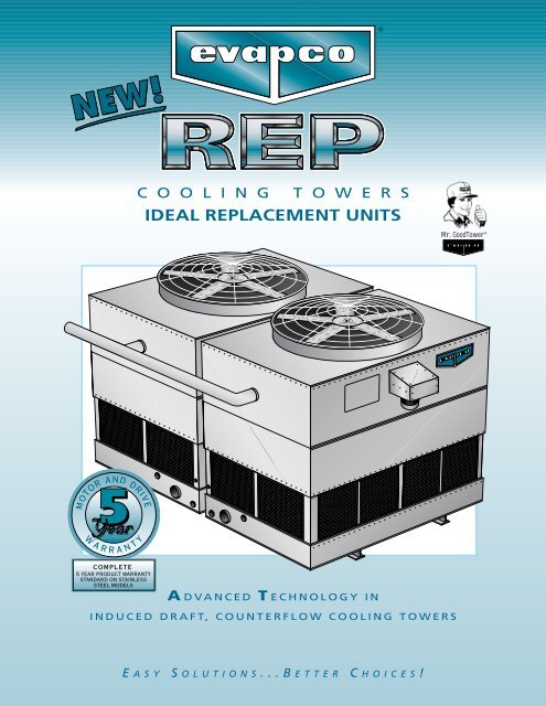
C O O L I N G T O W E R S<br />
IDEAL <strong>REP</strong>LACEMENT UNITS<br />
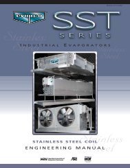
Mr. GoodTower ®<br />
A DVANCED T ECHNOLOGY IN<br />
INDUCED DRAFT, COUNTERFLOW COOLING TOWERS<br />
E ASY S OLUTIONS...BETTER C HOICES!
TWO CELL END INLET COOLING TOWERS<br />
IDEAL <strong>REP</strong>LACEMENT FOR CROSSFLOW UNITS<br />
MODELS <strong>REP</strong> 217-111 TO <strong>REP</strong> 224-920 / 367-1600 NOMINAL TONS<br />
LOW INSTALLATION COSTS - CONTRACTOR SAVINGS<br />
The <strong>REP</strong>’s fit tight enclosures and match up with crossflow layouts, piping, and steel, while still offering<br />
the maintenance and operational advantages of EVAPCO’s induced draft counterflow cooling towers.<br />
Layout Savings<br />
The <strong>REP</strong> counterflow method of heat transfer is the most efficient in the industry, resulting in a plan area up to 35%<br />
less than a comparable sized crossflow tower. The <strong>REP</strong>’s smaller plan area enables it to be located in smaller, less<br />
costly enclosures.<br />
<strong>REP</strong> units draw air from all four sides, so it is ideal for tight replacement projects. The <strong>REP</strong> can be placed close to a<br />
surrounding wall with little or no effect on unit capacity. The <strong>REP</strong> ’s are ideal for matching existing crossflow layouts.<br />
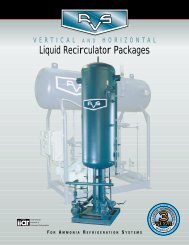
Piping Savings<br />
All piping connections are on one end, thereby reducing piping costs and installation time. Conventional doubleflow<br />
crossflow cooling towers require two water inlet connections per cell. The counterflow <strong>REP</strong> design requires only one<br />
inlet connection per cell, thereby significantly reducing the expensive piping, piping support and flow balancing<br />
valves required with the crossflow design. The pressurized water distribution system in <strong>REP</strong> units do not require flow<br />
balancing valves.<br />
Typical (2) Cell Crossflow Piping<br />
<strong>REP</strong> Simplified Piping<br />
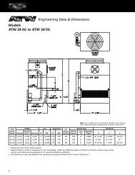
Steel Savings<br />
The two cell <strong>REP</strong> units may be supported in two ways - see Option A and B below. In Option A, the two cells are supported<br />
by three steel “I” beams running the entire length of the units. In Option B, the two cells are supported by<br />
two steel “I” beams running across the width of the cells. Option B matches the typical crossflow supporting steel<br />
arrangement. This flexibility enables <strong>REP</strong> units to sit on the existing structural steel for most replacement projects,<br />
thereby resulting in lower installation costs.<br />
Option A<br />
Option B<br />
UNIT OUTLINE<br />
UNIT<br />
OUTLINE<br />
STRUCTURAL BEAM<br />
STRUCTURAL BEAM<br />
Operating Weight Savings<br />
The operating weight of <strong>REP</strong> units are approximately 35% less than conventional crossflow cooling towers. Due to<br />
the <strong>REP</strong> basin design and smaller plan area, less water is held in the unit during normal operation. Therefore, the<br />
structural support costs are reduced, and it is possible to locate the <strong>REP</strong> on a lighter roof, providing greater location<br />
flexibility.<br />
2
TWO CELL END INLET COOLING TOWERS<br />
IDEAL <strong>REP</strong>LACEMENT FOR CROSSFLOW UNITS<br />
MODELS <strong>REP</strong> 217-111 TO <strong>REP</strong> 224-920 / 367-1600 NOMINAL TONS<br />
LOW OPERATING COSTS - OWNER SAVINGS<br />
Horsepower Savings<br />
The fan motor horsepower of <strong>REP</strong> Cooling Towers is typically equal to or less than other manufacturers’ fan motor<br />
horsepower. Reduced horsepower selections can save thousands of dollars in energy costs per year.<br />
The two cell <strong>REP</strong>’s have two fan motors, thereby providing mechanical redundancy and multiple steps of capacity<br />
control. For additional energy savings, two speed motors are recommended.<br />
When replacing centrifugal fan cooling towers, <strong>REP</strong> units will typically reduce the horsepower by as much as 50%.<br />
Maintenance Savings<br />
<strong>REP</strong> units have the most serviceable cold water basin in the industry. Removal of the light-weight inlet louvers provides<br />
easy access to all four sides of the basin for maintenance.<br />
Access to the fan and water distribution system is from the side of the unit. Routine maintenance can be safely<br />
performed by standing on the EVAPCO fill, which acts as a working platform.<br />
Totally enclosed fan motors are positioned for external access. Belt tensioning is performed from the outside of<br />
the unit. Bearing lube lines are also extended to the outside of the unit for easy service.<br />
Maintenance on <strong>REP</strong> towers is simple and easy. Maintenance costs are kept to a minimum.<br />
Water & Chemical Savings<br />
The stair step design of the <strong>REP</strong> pan basin significantly reduces the water volume in the unit (up to 35%) compared<br />
to crossflow equipment.<br />
The drift rate for <strong>REP</strong> Towers is less than .001% of the recirculated water rate. The typical crossflow drift rate is<br />
.005%. For a 500 ton tower, EVAPCO’s annual water savings from drift alone is 14,976 gallons. Also, the two pass<br />
inlet louver design eliminates splashout and water loss.<br />
The induced draft counterflow <strong>REP</strong> design with the two pass inlet louvers block direct sunlight from entering the<br />
unit, thereby reducing the potential for algae formation and reducing chemical costs.<br />
Exclusive Five Year Warranty<br />
All EVAPCO <strong>REP</strong> units come with a standard five year motor and drive warranty. Included<br />
are all drive components on belt and gear drive units. This unique warranty is designed to<br />
offer the end user optimum protection against fan drive and motor failure. <strong>REP</strong> units with<br />
stainless steel construction also have an exclusive Five Year complete product warranty.<br />
LOW INSTALLATION COST + LOW OPERATING COST =<br />
<strong>REP</strong> TOWERS: THE IDEAL <strong>REP</strong>LACEMENT TOWER<br />
3
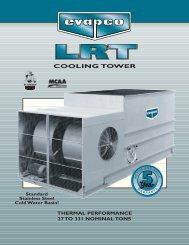
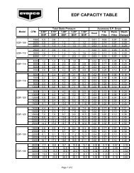
ENGINEERING DATA & DIMENSIONS<br />
MODELS <strong>REP</strong> 217-111 to <strong>REP</strong> 217-914<br />
19-5/8"<br />
8 BFW/GROOVED<br />
INLET<br />
8 BFW/GROOVED<br />
INLET<br />
2"<br />
ACCESS<br />
DOOR<br />
ACCESS<br />
DOOR<br />
55-1/2"<br />
50-3/4"<br />
H<br />
P<br />
B<br />
(2)3 MPT OVERFLOW<br />
(2)8 BFW/GROOVED<br />
OUTLET<br />
(2)2 MPT<br />
MAKE-UP<br />
(2)3 MPT<br />
DRAIN<br />
5-1/8"<br />
13/16"<br />
17' 4-1/8"<br />
23-1/8"<br />
15"<br />
7-1/2"<br />
63-3/4" 3/8"<br />
3-1/2"<br />
80-1/4"<br />
96-13/16"<br />
101-1/2"<br />
L<br />
Weights (LBS)<br />
Dimensions<br />
Fan<br />
Air<br />
Model Heaviest Motor Flow<br />
No. Shipping Operating Section (HP) (CFM) H † B P L<br />
<strong>REP</strong> 217-111 8700 15300 2220 (2) 7-1/2 91832 11’ 8-1/4” 7’ 3/4” 7’ 8-3/8” 10’ 5-1/4”<br />
<strong>REP</strong> 217-211 9340 15940 2540 (2) 7-1/2 90549 12’ 8-1/4” 8’ 3/4” 8’ 8-3/8” 10’ 5-1/4”<br />
<strong>REP</strong> 217-311 9400 16000 2540 (2) 10 99199 12’ 8-1/4” 8’ 3/4” 8’ 8-3/8” 10’ 5-1/4”<br />
<strong>REP</strong> 217-411 8900 15500 2230 (2) 15 114635 11’ 8-1/4” 7’ 3/4” 7’ 8-3/8” 10’ 5-1/4”<br />
<strong>REP</strong> 217-511 10100 16700 2890 (2) 10 97445 13’ 8-1/4” 9’ 3/4” 9’ 8-3/8” 10’ 5-1/4”<br />
<strong>REP</strong> 217-611 9540 16140 2540 (2) 15 112534 12’ 8-1/4” 8’ 3/4” 8’ 8-3/8” 10’ 5-1/4”<br />
<strong>REP</strong> 217-711 10240 16840 2890 (2) 15 110679 13’ 8-1/4” 9’ 3/4” 9’ 8-3/8” 10’ 5-1/4”<br />
<strong>REP</strong> 217-811 9640 16240 2540 (2) 20 123041 12’ 8-1/4” 8’ 3/4” 8’ 8-3/8” 10’ 5-1/4”<br />
<strong>REP</strong> 217-911 10400 17000 2890 (2) 25 129768 13’ 8-1/4” 9’ 3/4” 9’ 8-3/8” 10’ 5-1/4”<br />
Weights (LBS)<br />
Dimensions<br />
Fan<br />
Air<br />
Model Heaviest Motor Flow<br />
No. Shipping Operating Section (HP) (CFM) H † B P L<br />
<strong>REP</strong> 217-412 9420 17700 2520 (2) 20 136300 11’ 8-1/4” 7’ 3/4” 7’ 8-3/8” 11’ 11-3/4”<br />
<strong>REP</strong> 217-512 10060 18340 2550 (2) 15 122000 12’ 8-1/4” 8’ 3/4” 8’ 8-3/8” 11’ 11-3/4”<br />
<strong>REP</strong> 217-612 10140 18420 2550 (2) 20 133600 12’ 8-1/4” 8’ 3/4” 8’ 8-3/8” 11’ 11-3/4”<br />
<strong>REP</strong> 217-712 10920 19200 2940 (2) 20 131400 13’ 8-1/4” 9’ 3/4” 9’ 8-3/8” 11’ 11-3/4”<br />
<strong>REP</strong> 217-812 10180 18460 2550 (2) 25 143400 12’ 8-1/4” 8’ 3/4” 8’ 8-3/8” 11’ 11-3/4”<br />
<strong>REP</strong> 217-912 11000 19280 2940 (2) 30 149300 13’ 8-1/4” 9’ 3/4” 9’ 8-3/8” 11’ 11-3/4”<br />
Weights (LBS)<br />
Dimensions<br />
Fan<br />
Air<br />
Model Heaviest Motor Flow<br />
No. Shipping Operating Section (HP) (CFM) H † B P L<br />
<strong>REP</strong> 217-214 11580 20600 3180 (2) 15 137823 13’ 2-1/4” 8’ 6-3/4” 9’ 2-3/8” 13’ 11-3/4”<br />
<strong>REP</strong> 217-314 10880 19900 2770 (2) 25 164866 12’ 2-1/4” 7’ 6-3/4” 8’ 2-3/8” 13’ 11-3/4”<br />
<strong>REP</strong> 217-414 11660 20680 3180 (2) 20 150760 13’ 2-1/4” 8’ 6-3/4” 9’ 2-3/8” 13’ 11-3/4”<br />
<strong>REP</strong> 217-514 12560 21580 3630 (2) 20 148411 14’ 2-1/4” 9’ 6-3/4” 10’ 2-3/8” 13’ 11-3/4”<br />
<strong>REP</strong> 217-614 11700 20720 3180 (2) 25 161606 13’ 2-1/4” 8’ 6-3/4” 9’ 2-3/8” 13’ 11-3/4”<br />
<strong>REP</strong> 217-714 12600 21620 3630 (2) 25 158976 14’ 2-1/4” 9’ 6-3/4” 10’ 2-3/8” 13’ 11-3/4”<br />
<strong>REP</strong> 217-814 11740 20760 3180 (2) 30 171234 13’ 2-1/4” 8’ 6-3/4” 9’ 2-3/8” 13’ 11-3/4”<br />
<strong>REP</strong> 217-914 12640 21660 3630 (2) 30 168244 14’ 2-1/4” 9’ 6-3/4” 10’ 2-3/8” 13’ 11-3/4”<br />
Note: (1) An adequately sized bleed line must be installed in the cooling tower system to prevent build-up of impurities in the recirculated water.<br />
(2) Do not use catalog drawings for certified prints. Dimensions subject to change.<br />
(3) Connections larger than 3” are Beveled for Welding (BFW) and grooved for a mechanical coupling.<br />
(4) Adequate spacing must be allowed for access to the cooling tower.<br />
(5) Unit can operate as two (2) independent cells with the addition of a<br />
flume plate or water tight partition.<br />
† Height includes fan guard which ships factory mounted.<br />
4
THERMAL PERFORMANCE<br />
<strong>REP</strong> 217-111 to <strong>REP</strong> 217-911<br />
Temp<br />
Cooling Capacity in GPM<br />
EWT 90° 95° 90° 95° 95° 90° 95° 95° 95° 100°<br />
Model Motor LWT 80° 80° 80° 80° 85° 80° 80° 85° 85° 85°<br />
No. HP WB 68° 68° 70° 70° 70° 72° 72° 72° 75° 75°<br />
<strong>REP</strong> 217-111 (2) 7-1/2 1372 1032 1197 902 1798 1018 774 1653 1390 1058<br />
<strong>REP</strong> 217-211 (2) 7-1/2 1462 1127 1291 1000 1869 1112 875 1730 1480 1155<br />
<strong>REP</strong> 217-311 (2) 10 1589 1237 1408 1100 2018 1221 966 1872 1608 1265<br />
<strong>REP</strong> 217-411 (2) 15 1682 1287 1477 1139 2158 1270 995 1997 1703 1318<br />
<strong>REP</strong> 217-511 (2) 10 1684 1349 1510 1220 2112 1334 1094 1963 1702 1375<br />
<strong>REP</strong> 217-611 (2) 15 1830 1443 1632 1294 2304 1426 1146 2141 1851 1474<br />
<strong>REP</strong> 217-711 (2) 15 1913 1536 1718 1396 2400 1520 1256 2231 1934 1566<br />
<strong>REP</strong> 217-811 (2) 20 2037 1619 1823 1459 2556 1601 1300 2376 2059 1653<br />
<strong>REP</strong> 217-911 (2) 25 2233 1795 2005 1633 2700 1776 1476 2603 2257 1829<br />
Temp<br />
Cooling Capacity in GPM<br />
EWT 95° 100° 95° 97° 100° 102° 95° 96° 100° 102°<br />
Model Motor LWT 85° 85° 85° 87° 85° 85° 85° 86° 85° 85°<br />
No. HP WB 76° 76° 78° 78° 78° 78° 80° 80° 80° 80°<br />
<strong>REP</strong> 217-111 (2) 7-1/2 1300 992 1102 1386 847 782 865 1011 669 662<br />
<strong>REP</strong> 217-211 (2) 7-1/2 1393 1088 1199 1476 942 883 961 1106 771 727<br />
<strong>REP</strong> 217-311 (2) 10 1516 1196 1311 1604 1039 975 1059 1215 857 808<br />
<strong>REP</strong> 217-411 (2) 15 1597 1241 1369 1698 1073 1004 1095 1262 872 818<br />
<strong>REP</strong> 217-511 (2) 10 1612 1309 1418 1698 1163 1102 1182 1327 990 944<br />
<strong>REP</strong> 217-611 (2) 15 1749 1397 1525 1847 1227 1155 1249 1418 1020 964<br />
<strong>REP</strong> 217-711 (2) 15 1833 1493 1614 1929 1333 1265 1355 1513 1139 1087<br />
<strong>REP</strong> 217-811 (2) 20 1949 1570 1708 2054 1387 1310 1411 1593 1165 1103<br />
<strong>REP</strong> 217-911 (2) 25 2139 1745 1885 2252 1561 1486 1585 1768 1345 1285<br />
<strong>REP</strong> 217-412 to <strong>REP</strong> 217-912<br />
Temp<br />
Cooling Capacity in GPM<br />
EWT 90° 95° 90° 95° 95° 90° 95° 95° 95° 100°<br />
Model Motor LWT 80° 80° 80° 80° 85° 80° 80° 85° 85° 85°<br />
No. HP WB 68° 68° 70° 70° 70° 72° 72° 72° 75° 75°<br />
<strong>REP</strong> 217-412 (2) 20 1977 1522 1742 1350 2525 1502 1181 2340 2001 1577<br />
<strong>REP</strong> 217-512 (2) 15 1992 1566 1773 1403 2510 1548 1237 2332 2014 1601<br />
<strong>REP</strong> 217-612 (2) 20 2190 1736 1958 1562 2750 1717 1387 2557 2214 1773<br />
<strong>REP</strong> 217-712 (2) 20 2253 1810 2023 1646 2825 1792 1485 2626 2277 1845<br />
<strong>REP</strong> 217-812 (2) 25 2338 1864 2095 1680 2933 1843 1498 2726 2364 1902<br />
<strong>REP</strong> 217-912 (2) 30 2484 1997 2231 1817 * 1976 1642 2896 2510 2035<br />
Temp<br />
Cooling Capacity in GPM<br />
EWT 95° 100° 95° 97° 100° 102° 95° 96° 100° 102°<br />
Model Motor LWT 85° 85° 85° 87° 85° 85° 85° 86° 85° 85°<br />
No. HP WB 76° 76° 78° 78° 78° 78° 80° 80° 80° 80°<br />
<strong>REP</strong> 217-412 (2) 20 1882 1469 1615 1996 1273 1192 1299 1493 1038 978<br />
<strong>REP</strong> 217-512 (2) 15 1903 1515 1656 2009 1329 1250 1354 1539 1101 1042<br />
<strong>REP</strong> 217-612 (2) 20 2096 1680 1832 2209 1481 1400 1511 1708 1238 1175<br />
<strong>REP</strong> 217-712 (2) 20 2158 1759 1902 2272 1573 1495 1597 1783 1347 1287<br />
<strong>REP</strong> 217-812 (2) 25 2240 1804 1963 2358 1596 1512 1625 1833 1344 1275<br />
<strong>REP</strong> 217-912 (2) 30 2380 1941 2097 2505 1737 1653 1763 1967 1495 1429<br />
*Flow exceeds maximum hydraulic limit.<br />
<strong>REP</strong> 217-214 to <strong>REP</strong> 217-914<br />
Temp<br />
Cooling Capacity in GPM<br />
EWT 90° 95° 90° 95° 95° 90° 95° 95° 95° 100°<br />
Model Motor LWT 80° 80° 80° 80° 85° 80° 80° 85° 85° 85°<br />
No. HP WB 68° 68° 70° 70° 70° 72° 72° 72° 75° 75°<br />
<strong>REP</strong> 217-214 (2) 15 2201 1724 1955 1541 2781 1702 1355 2583 2227 1762<br />
<strong>REP</strong> 217-314 (2) 25 2381 1838 2102 1633 3030 1814 1432 2808 2411 1881<br />
<strong>REP</strong> 217-414 (2) 20 2420 1909 2158 1714 3042 1887 1520 2828 2446 1950<br />
<strong>REP</strong> 217-514 (2) 20 2492 2001 2238 1819 3126 1981 1637 2906 2520 2039<br />
<strong>REP</strong> 217-614 (2) 25 2618 2079 2341 1872 3284 2055 1666 3053 2646 2122<br />
<strong>REP</strong> 217-714 (2) 25 2703 2173 2426 1976 3419 2149 1784 3151 2732 2214<br />
<strong>REP</strong> 217-814 (2) 30 2768 2209 2480 1993 3472 2184 1780 3227 2798 2253<br />
<strong>REP</strong> 217-914 (2) 30 2856 2295 2564 2088 3507 2272 1887 3329 2886 2338<br />
Temp<br />
Cooling Capacity in GPM<br />
EWT 95° 100° 95° 97° 100° 102° 95° 96° 100° 102°<br />
Model Motor LWT 85° 85° 85° 87° 85° 85° 85° 86° 85° 85°<br />
No. HP WB 76° 76° 78° 78° 78° 78° 80° 80° 80° 80°<br />
<strong>REP</strong> 217-214 (2) 15 2100 1666 1823 2221 1455 1367 1484 1692 1201 1137<br />
<strong>REP</strong> 217-314 (2) 25 2268 1776 1952 2405 1544 1434 1573 1796 1263 1178<br />
<strong>REP</strong> 217-414 (2) 20 2313 1849 2017 2440 1626 1524 1655 1872 1353 1272<br />
<strong>REP</strong> 217-514 (2) 20 2387 1945 2102 2514 1738 1646 1765 1970 1484 1414<br />
<strong>REP</strong> 217-614 (2) 25 2504 2015 2193 2639 1780 1680 1810 2044 1492 1413<br />
<strong>REP</strong> 217-714 (2) 25 2589 2111 2281 2725 1887 1796 1917 2139 1620 1548<br />
<strong>REP</strong> 217-814 (2) 30 2651 2142 2326 2791 1895 1788 1928 2169 1597 1509<br />
<strong>REP</strong> 217-914 (2) 30 2735 2231 2410 2879 1996 1899 2027 2261 1718 1642<br />
To Make a Selection: Locate the column with the desired operating temperature conditions. Read down the column until you find the GPM<br />
equal to or greater than the flow required. Read horizontally to the left to find the model number of the unit that will perform the duty.<br />
For selections and conditions other than those stated, consult your EVAPSPEC II Selection Program or local EVAPCO representative.<br />
5
ENGINEERING DATA & DIMENSIONS<br />
MODELS <strong>REP</strong> 224-018 to <strong>REP</strong> 224-920<br />
7"<br />
ACCESS<br />
DOOR<br />
ACCESS<br />
DOOR<br />
(2)10 BFW/GROOVED<br />
INLET<br />
71"<br />
2"<br />
T<br />
H<br />
P<br />
98-1/2"<br />
(2)2 MPT<br />
MAKE-UP<br />
25-1/8"<br />
17"<br />
3-1/2"<br />
96-7/8"<br />
117-7/8"<br />
137-1/4"<br />
(2)3 MPT OVERFLOW<br />
8-1/2"<br />
*(2)10 BFW/GROOVED OUTLET<br />
(2)3 MPT DRAIN<br />
5-1/8"<br />
7/8"<br />
1-3/8"<br />
L<br />
142"<br />
24' 1-1/8"<br />
Weights (LBS)<br />
Dimensions<br />
Fan<br />
Air<br />
Model Heaviest Motor Flow<br />
No. Shipping Operating Section (HP) (CFM) H † T P L<br />
<strong>REP</strong> 224-018 19580 39600 6810 (2) 25 258400 16’ 6-1/2” 8’ 4” 11’ 1-1/4” 18’<br />
<strong>REP</strong> 224-118 19800 39820 6920 (2) 30 274000 16’ 6-1/2” 8’ 4” 11’ 1-1/4” 18’<br />
<strong>REP</strong> 224-218 21140 41160 7590 (2) 25 254100 17’ 6-1/2” 9’ 4” 12’ 1-1/4” 18’<br />
<strong>REP</strong> 224-318 20320 40340 7180 (2) 40 300100 16’ 6-1/2” 8’ 4” 11’ 1-1/4” 18’<br />
<strong>REP</strong> 224-418 21360 41380 7700 (2) 30 269100 17’ 6-1/2” 9’ 4” 12’ 1-1/4” 18’<br />
<strong>REP</strong> 224-518 22840 42860 8440 (2) 30 264800 18’ 6-1/2” ††10’ 4” 13’ 1-1/4” 18’<br />
<strong>REP</strong> 224-618 21880 41900 7960 (2) 40 294400 17’ 6-1/2” 9’ 4” 12’ 1-1/4” 18’<br />
<strong>REP</strong> 224-718 22000 42020 8020 (2) 50 315900 17’ 6-1/2” 9’ 4” 12’ 1-1/4” 18’<br />
<strong>REP</strong> 224-818 23480 43500 8760 (2) 50 310300 18’ 6-1/2” ††10’ 4” 13’ 1-1/4” 18’<br />
<strong>REP</strong> 224-918 23700 43720 8870 (2) 60 328700 18’ 6-1/2” ††10’ 4” 13’ 1-1/4” 18’<br />
Weights (LBS)<br />
Dimensions<br />
Fan<br />
Air<br />
Model Heaviest Motor Flow<br />
No. Shipping Operating Section (HP) (CFM) H † T P L<br />
<strong>REP</strong> 224-720 24840 47200 9260 (2) 40 321200 18’ 6-1/2” ††10’ 4” 13’ 1-1/4” 20’<br />
<strong>REP</strong> 224-820 24960 47320 9320 (2) 50 316000 18’ 6-1/2” ††10’ 4” 13’ 1-1/4” 20’<br />
<strong>REP</strong> 224-920 25180 47540 9430 (2) 60 334800 18’ 6-1/2” ††10’ 4” 13’ 1-1/4” 20’<br />
Note: (1) An adequately sized bleed line must be installed in the cooling tower system to prevent build-up of impurities in the recirculated water.<br />
(2) Do not use catalog drawings for certified prints. Dimensions subject to change.<br />
(3) Connections larger than 3” are Beveled for Welding (BFW) and grooved for a mechanical coupling.<br />
(4) Adequate spacing must be allowed for access to the cooling tower.<br />
(5) Unit can operate as two (2) independent cells with the addition of a flume plate or water tight partition.<br />
† Height does not include fan guard.<br />
†† Fan guard ships loose for field mounting.<br />
* (2)12” BFW/Grooved Outlet on models 224-720 thru 224-920.<br />
6
THERMAL PERFORMANCE<br />
<strong>REP</strong> 224-018 to <strong>REP</strong> 224-918<br />
Temp<br />
Tower Capacity in USGPM at the Following Temperature Conditions (°F)<br />
EWT 90° 95° 90° 95° 95° 90° 95° 95° 95° 100°<br />
Model Motor LWT 80° 80° 80° 80° 85° 80° 80° 85° 85° 85°<br />
No. HP WB 68° 68° 70° 70° 70° 72° 72° 72° 75° 75°<br />
<strong>REP</strong> 224-018 (2) 25 3788 2886 3321 2543 4904 2847 2202 4528 3837 2955<br />
<strong>REP</strong> 224-118 (2) 30 3985 3045 3498 2692 5129 3005 2345 4742 4036 3118<br />
<strong>REP</strong> 224-218 (2) 25 4119 3226 3660 2884 5203 3186 2538 4833 4166 3298<br />
<strong>REP</strong> 224-318 (2) 40 4373 3371 3857 2993 5576 3328 2621 5169 4427 3449<br />
<strong>REP</strong> 224-418 (2) 30 4340 3415 3865 3059 5468 3375 2699 5082 4389 3488<br />
<strong>REP</strong> 224-518 (2) 30 4491 3604 4032 3275 5632 3566 2943 5235 4540 3674<br />
<strong>REP</strong> 224-618 (2) 40 4763 3776 4257 3397 5980 3734 3020 5559 4816 3855<br />
<strong>REP</strong> 224-718 (2) 50 5100 4066 4569 3667 6397 4020 3274 5946 5155 4148<br />
<strong>REP</strong> 224-818 (2) 50 5313 4271 4770 3885 6546 4226 3510 6194 5370 4351<br />
<strong>REP</strong> 224-918 (2) 60 5519 4436 4955 4037 * 4390 3648 6433 5578 4520<br />
Temp<br />
Tower Capacity in USGPM at the Following Temperature Conditions (°F)<br />
EWT 95° 100° 95° 97° 100° 102° 95° 96° 100° 102°<br />
Model Motor LWT 85° 85° 85° 87° 85° 85° 85° 86° 85° 85°<br />
No. HP WB 76° 76° 78° 78° 78° 78° 80° 80° 80° 80°<br />
<strong>REP</strong> 224-018 (2) 25 3596 2774 3070 3826 2387 2227 2445 2829 1919 1796<br />
<strong>REP</strong> 224-118 (2) 30 3786 2938 3241 4025 2536 2368 2587 2987 2059 1922<br />
<strong>REP</strong> 224-218 (2) 25 3930 3119 3412 4155 2724 2559 2777 3168 2251 2128<br />
<strong>REP</strong> 224-318 (2) 40 4164 3256 3579 4415 2826 2645 2884 3309 2309 2173<br />
<strong>REP</strong> 224-418 (2) 30 4148 3303 3609 4378 2897 2726 2953 3357 2402 2272<br />
<strong>REP</strong> 224-518 (2) 30 4303 3502 3787 4529 3123 2964 3174 3549 2665 2545<br />
<strong>REP</strong> 224-618 (2) 40 4557 3661 3984 4804 3228 3044 3286 3714 2698 2556<br />
<strong>REP</strong> 224-718 (2) 50 4884 3942 4282 5143 3486 3299 3546 3999 2936 2786<br />
<strong>REP</strong> 224-818 (2) 50 5090 4152 4484 5357 3714 3534 3771 4206 3195 3054<br />
AT 224-918 (2) 60 5287 4313 4658 5565 3860 3673 3919 4369 3325 3180<br />
*Flow exceeds maximum hydraulic limit.<br />
<strong>REP</strong> 224-720 to <strong>REP</strong> 224-920<br />
Temp<br />
Tower Capacity in USGPM at the Following Temperature Conditions (°F)<br />
EWT 90° 95° 90° 95° 95° 90° 95° 95° 95° 100°<br />
Model Motor LWT 80° 80° 80° 80° 85° 80° 80° 85° 85° 85°<br />
No. HP WB 68° 68° 70° 70° 70° 72° 72° 72° 75° 75°<br />
<strong>REP</strong> 224-720 (2) 40 4998 4012 4487 3646 6267 3970 3275 5826 5051 4089<br />
<strong>REP</strong> 224-820 (2) 50 5414 4350 4861 3956 6789 4304 3568 6311 5472 4434<br />
<strong>REP</strong> 224-920 (2) 60 5622 4518 5048 4108 7049 4471 3710 6553 5683 4604<br />
Temp<br />
Tower Capacity in USGPM at the Following Temperature Conditions (°F)<br />
EWT 95° 100° 95° 97° 100° 102° 95° 96° 100° 102°<br />
Model Motor LWT 85° 85° 85° 87° 85° 85° 85° 86° 85° 85°<br />
No. HP WB 76° 76° 78° 78° 78° 78° 80° 80° 80° 80°<br />
<strong>REP</strong> 224-720 (2) 40 4787 3893 4214 5039 3475 3303 3536 3950 2968 2837<br />
<strong>REP</strong> 224-820 (2) 50 5187 4222 4569 5459 3775 3596 3838 4284 3236 3097<br />
<strong>REP</strong> 224-920 (2) 60 5385 4393 4744 5669 3928 3736 3989 4450 3374 3224<br />
To Make a Selection: Locate the column with the desired operating temperature conditions. Read down the column until you find the GPM equal to or greater<br />
than the flow required. Read horizontally to the left to find the model number of the unit that will perform the duty.<br />
For selections and conditions other than those stated, consult your EVAPSPEC II Selection Program or local EVAPCO representative.<br />
7
STRUCTURAL STEEL SUPPORT<br />
MODELS <strong>REP</strong> 217-111 to <strong>REP</strong> 224-920<br />
L<br />
Option A: Suggested Three “I” Beam Arrangement<br />
W<br />
5-1/8"<br />
Gap<br />
Dimension<br />
End Elevation<br />
Plan View<br />
Three “I” Beams Required (By Others)<br />
Dimensions<br />
Model No. W L<br />
<strong>REP</strong> 217-111 to 911 17’ 4-1/8” 10’ 5-1/4”<br />
<strong>REP</strong> 217-412 to 912 17’ 4-1/8” 11’ 11-3/4”<br />
<strong>REP</strong> 217-214 to 914 17’ 4-1/8” 13’ 11-3/4”<br />
<strong>REP</strong> 224-018 to 918 24’ 1-1/8” 18’ 0”<br />
<strong>REP</strong> 224-720 to 920 24’ 1-1/8” 20’ 0”<br />
MODELS <strong>REP</strong> 217-111 to <strong>REP</strong> 224-920<br />
Option B<br />
Option B: Suggested Two “I” Beam Arrangement<br />
In Option B, the two cells are supported by two steel “I” beams<br />
running across the width of the cells.<br />
Consult your EVAPCO representative for this alternate steel<br />
support and factory certified steel support drawings.<br />
UNIT<br />
OUTLINE<br />
STRUCTURAL BEAM<br />
Notes:<br />
Models <strong>REP</strong> 217-111 through 224-920<br />
1. These are suggested arrangements for preliminary layout purposes. Consult your EVAPCO representative for factory certified steel support<br />
drawings.<br />
2. The recommended support for option A is structural “I” beams located under the outer flanges and running the entire length of the<br />
unit. The unit should be elevated to allow access underneath the unit and to the roof below. Mounting holes, 3/4” in diameter, are<br />
located in the bottom flanges of the pan to provide for bolting to the structural steel.<br />
3. Beams should be sized in accordance with accepted structural practices. Maximum deflection of beam under unit to be 1/360 of the unit<br />
length, not to exceed 1/2”.<br />
4. Beams should be level before setting the unit in place. Do not level the unit by shimming between it and the “I” beams.<br />
5. Support beams and anchor bolts are to be furnished by others.<br />
6. Dimensions, weights and data are subject to change without notice. Refer to the factory certified drawings for exact dimensions.<br />
7. For alternate layout arrangements please consult the factory. NOTE: OPTIONAL BOTTOM CONNECTIONS WILL REQUIRE THE UNIT TO BE<br />
ELEVATED TO ALLOW FOR PIPING.<br />
8
APPLICATIONS<br />
System Design<br />
<strong>REP</strong> Cooling Towers are constructed of heavy duty materials<br />
and are designed for superior performance providing<br />
long, trouble-free operation. However, proper equipment<br />
selection, installation and maintenance is necessary<br />
to ensure optimum unit performance. Several of the<br />
major considerations when designing and operating a<br />
cooling tower installation are presented in the following<br />
paragraphs. For additional information, contact your<br />
local EVAPCO representative.<br />
Air Circulation<br />
The location of a cooling tower is an important consideration<br />
when reviewing system design. Since cooling towers<br />
consume large quantities of air, adequate spacing<br />
around the unit is necessary for it to perform properly.<br />
The best place to locate any cooling tower is on a roof or<br />
at ground level away from walls and other obstructions.<br />
Cooling towers that are located in wells, enclosures, or<br />
are adjacent to high walls must be properly located to<br />
avoid the effects of recirculation. Recirculation occurs<br />
when some of the hot moist discharge air leaving the<br />
cooling tower flows back into the fresh air inlet. When<br />
recirculation causes the inlet wet bulb temperature to the<br />
cooling tower to be increased, the capacity of the cooling<br />
tower is decreased. Refer to EVAPCO Bulletin 311,<br />
Equipment Layout Manual, for the recommended layout<br />
guidelines for cooling towers.<br />
Maintaining the Recirculated Water System<br />
A cooling tower removes heat by evaporating a portion<br />
of the recirculated spray water. As a general rule, a cooling<br />
tower evaporates 3 US GPM per 100 tons of cooling<br />
capacity. As this water evaporates, it leaves behind all of<br />
its mineral content and impurities. Therefore, it is important<br />
to bleed an amount equal to that which is evaporated<br />
to prevent the buildup of impurities. If this is not<br />
done, the mineral content in the water will increase until<br />
the solids eventually deposit in the unit, causing heavy<br />
scaling. The bleed line should be installed in the external<br />
piping of the unit. It must be properly sized for the<br />
application and be provided with a metering valve and<br />
flow measurement device to allow for field adjustment of<br />
the bleed rate.<br />
Water Treatment<br />
EVAPCO recommends that all cooling tower users should<br />
consult with a reputable water treatment company familiar<br />
with local water conditions in order to determine the<br />
extent and type of water treatment program recommended<br />
for each specific application. Any chemical<br />
water treatment used must be compatible with the galvanized<br />
construction of the unit. If acid is used for treatment,<br />
it should be accurately metered and the concentration<br />
properly controlled. The pH of the water should be<br />
maintained between 6.5 and 8.0. In order to prevent<br />
“white rust”, the galvanized steel in the unit may require<br />
routine passivation of the steel when the system is operating<br />
in the higher pH levels.<br />
Batch chemical feeding is not recommended because it<br />
does not afford the proper degree of control. If acid<br />
cleaning is required extreme caution must be exercised<br />
and only inhibited acids compatible with galvanized steel<br />
construction should be used. Consult EVAPCO’S<br />
Maintenance Bulletin 112 for additional information.<br />
Capacity Control<br />
The design wet bulb temperature for which a cooling<br />
tower is sized occurs only a small percentage of the time.<br />
Since the wet bulb temperature is lower than design<br />
much of the time, and cooling loads tend to fluctuate,<br />
some form of capacity control will be required. The simplest<br />
form of capacity control is to cycle the fans on and<br />
off. However, this type of control results in larger temperature<br />
differentials and does not provide close control<br />
of the leaving water temperature.<br />
A better method of capacity control is to use two speed<br />
fan motors, which add a second step of control. Two<br />
speed motors are an excellent method of capacity control<br />
for the <strong>REP</strong> Cooling Tower. This arrangement gives<br />
capacity steps of 10% (fans off), 60% (Fans at half speed)<br />
and 100%. A temperature controller can be supplied to<br />
set control at 5& F increments, so that close temperature<br />
control can be maintained without excessive cycling of<br />
the fan motor.<br />
Two speed motors also reduce operating costs. At half<br />
speed, the motor draws approximately 15% of the full<br />
load power. Since the maximum wet bulb temperature<br />
and maximum load very seldom coincide, the cooling<br />
tower will actually operate at half speed about 80% of<br />
the time. Therefore, power costs will be reduced by 85%<br />
during the major portion of the year.<br />
A third advantage of two speed motors is that noise levels<br />
are reduced by approximately 6 dB when operating at<br />
half speed. Since both the load and wet bulb temperature<br />
are normally lower at night, the sound generated by<br />
the cooling tower will be substantially reduced during<br />
the most noise sensitive time period.<br />
For multiple cell units, both fan cycling and two speed<br />
motors can be used to provide additional steps of control.<br />
The combination of fan cycling and two speed motors<br />
offers a simple and inexpensive means of controlling unit<br />
capacity along with substantially reducing the energy<br />
costs of the cooling tower.<br />
Piping<br />
Cooling tower piping should be designed and installed in<br />
accordance with generally accepted engineering practices.<br />
All piping should be supported by properly designing<br />
hangers and supports with allowances made for possible<br />
expansion and contraction of the piping system. No<br />
external loads should be placed on the cooling tower<br />
connections. Do NOT anchor any of the piping supports<br />
to the cooling tower or its framework.<br />
Control of Biological Contamination<br />
Water quality should be checked regularly for biological<br />
contamination. If biological contamination is detected, a<br />
more aggressive water treatment and mechanical cleaning<br />
program should be undertaken. The water treatment<br />
program should be performed by a qualified water treatment<br />
company. It is important that all internal surfaces<br />
be kept clean of accumulated dirt and sludge. In addition,<br />
the drift eliminators should be checked periodically<br />
to ensure that they are clean and have not been damaged.<br />
Note: The location of the cooling tower must be considered<br />
during the equipment layout stages of a project. It<br />
is important to prevent the discharge air (potential of<br />
biological contamination) from being introduced into the<br />
fresh air intakes of the building.<br />
9
APPLICATIONS<br />
Special Applications of the <strong>REP</strong> Cooling Tower<br />
The <strong>REP</strong> Cooling Tower is designed for all air conditioning and industrial cooling applications. There are some design<br />
situations where special consideration must be given for the type and size of unit selected, such as, materials of construction,<br />
thermal performance, water quality, unit layout and local fire codes. Some of these special applications are<br />
described below.<br />
Freecooling<br />
Freecooling allows chilled water to be produced by the<br />
cooling tower without the use of a mechanical chiller<br />
during low ambient conditions. The freecooling or<br />
economizer mode of an air conditioning system is used<br />
to save $/KWH when the conditions allow the water in<br />
the tower to be cooled to “chiller” like temperatures,<br />
typically 42-45F LWT.<br />
EVAPCO’s counterflow cooling towers are well suited for<br />
free cooling applications. The counterflow fill design<br />
helps prevent ice formation with its even temperature<br />
gradient through the fill section and enclosed location<br />
blocking it from the elements. However, special caution<br />
must be taken when selecting, sizing and operating a<br />
cooling tower during normal winter or severe winter<br />
applications.<br />
Please consult EVAPCO’s Engineering Bulletin on Free<br />
Cooling Operation of Open Cooling Towers to assist in<br />
selecting a tower for a freecooling application.<br />
High Temperature Applications<br />
EVAPCO’s <strong>REP</strong> Cooling Tower as standard is capable of<br />
handling up to 130°F entering water temperature, which<br />
is higher than most crossflow cooling tower fill sheets. It<br />
will not deform or degrade at a continuous temperature<br />
application of 130°F.<br />
However, there are applications where a higher temperature<br />
rated fill is required. For these applications, a fill<br />
material is available as an option which allows the entering<br />
water temperature to operate at a continuous 150°F.<br />
Please consult the factory for selections of higher temperature<br />
fill Cooling Towers.<br />
Rigging Guidelines<br />
The rigging requirements of the <strong>REP</strong> Cooling Tower are<br />
covered in EVAPCO’s Rigging Bulletins which are available<br />
from your local EVAPCO Representative or the factory.<br />
Consult Bulletin# 148.<br />
These guidelines cover recommended lifting methods for<br />
the top and bottom sections of the cooling tower and<br />
how to mate the sections together. In addition, installation<br />
instructions for the flume box, flume plate, vertical<br />
& horizontal splash guards (multi-cell units only) fan<br />
screens and motor/gearbox davits are also provided.<br />
Consult the Factory or your local EVAPCO<br />
representative for:<br />
Layout Guidelines<br />
Bypass Connection Sizing and Location<br />
Equalizer Connection Sizing and Location<br />
Remote Sump Connection Sizing and Location<br />
Cooling Water Contribution to Remote Sump Tanks<br />
Field Thermal Performance Tests<br />
Seismic and Wind Load Applications<br />
Operating and Maintenance Questions<br />
Pan Heater Sizing for Low Ambient Operation<br />
Factory Mutual<br />
Vibration Isolation<br />
Dirty Water Applications<br />
The EVAPAK ® fill used in the <strong>REP</strong> Cooling Tower is<br />
designed to operate in almost all cooling water applications.<br />
However, there are some “dirty” water applications<br />
where the standard fill spacing is not adequate,<br />
such as a pulp and paper mill cooling tower or other<br />
application where heavy particulate will be mixed in<br />
with the water.<br />
Please consult the factory for a special cooling tower<br />
selection (for this application) utilizing EVAPCO’s<br />
exclusive EF19 and EVF 19 anti-fouling fill.<br />
10
MECHANICAL SPECIFICATIONS<br />
Furnish and install as shown on the plans an EVAPCO Model<br />
__________ induced draft counterflow cooling tower. Each unit<br />
shall have the capacity to cool __________ GPM of water from<br />
__________ ˚F to __________ ˚F with a __________ ˚F entering wet<br />
bulb temperature.<br />
Pan<br />
The pan shall be constructed of G-235 hot-dip galvanized steel<br />
for long life and durability. G-235 hot-dip galvanized steel designates<br />
an average coating thickness of 2.35 ounces of zinc per<br />
square foot on the steel. Standard pan accessories shall include<br />
overflow, drain, anti-vortexing hood, Type 304 Stainless Steel<br />
strainers, and brass make-up valve with plastic float. The entire<br />
pan area shall incorporate a stepped configuration for reduced<br />
water volume, lower operating weight and easier pan maintenance.<br />
The upper and lower pan bottoms shall be sloped to provide<br />
positive drainage of the complete basin section. Depressed<br />
side outlet sumps which are not an integral part of the basin<br />
shall not be acceptable.<br />
Casing<br />
The casing shall be constructed of G-235 hot-dip galvanized steel.<br />
The casing panels shall totally encase the sides of the fill section<br />
to protect the surface from direct atmospheric contact.<br />
Water Piping Connections<br />
All water piping connections, such as the inlet, outlet, overflow,<br />
make-up and drain connections are to be located on the same<br />
side to minimize piping costs and to reduce installation time.<br />
Models <strong>REP</strong> 217-111 to 217-914 Fan Motor(s)<br />
__________ HP totally enclosed fan cooled (T.E.F.C.) ball bearing<br />
fan motor(s) with 1.15 service factor shall be furnished suitable<br />
for cooling tower service on __________ volts, __________ hertz,<br />
and __________ phase. Motor(s) shall be mounted on an<br />
adjustable base which is mounted on the side of the unit for<br />
service. A hinged protective cover shall shield the motor and<br />
sheave from the weather.<br />
Drive<br />
The fan drive shall be a multigroove, solid back V-belt type with<br />
taper lock sheaves designed for 150% of the motor nameplate<br />
horsepower. The belt material shall be neoprene reinforced<br />
with polyester cord and specifically designed for cooling tower<br />
service. A hinged protective cover shall shield the motor and<br />
sheave from the weather. Belt adjustment shall be accomplished<br />
from the exterior of the unit. Bearing lube lines shall be extended<br />
to the exterior of the unit for easy maintenance. All sheaves<br />
located in the airstream shall be constructed of aluminum alloy,<br />
vented guards shall not be acceptable. If internal belt adjustment<br />
is necessary, an internal working platform and ladder is<br />
required to access the drive system.<br />
Models <strong>REP</strong> 224-018 to 224-920<br />
Fan Motor(s)<br />
__________ HP totally enclosed air over (T.E.A.O.) ball bearing<br />
fan motor(s) with 1.15 service factor shall be furnished suitable<br />
for cooling tower service on __________ volts, __________ hertz,<br />
and __________ phase. Motor(s) shall be mounted on an<br />
adjustable base which allows the motor to swing to the outside<br />
of the unit for servicing.<br />
Drive<br />
The fan drive shall be a multigroove, solid back V-belt type<br />
with taper lock sheaves designed for 150% of the motor nameplate<br />
horsepower. The belt material shall be neoprene reinforced<br />
with polyester cord and specifically designed for cooling<br />
tower service. Fan and motor sheaves shall be aluminum alloy<br />
construction. Belt adjustment shall be accomplished from the<br />
exterior of the unit. Bearing lube lines shall be extended to the<br />
exterior of the unit for easy maintenance. All sheaves located<br />
in the airstream shall be constructed of aluminum alloy, vented<br />
guards shall not be acceptable. If internal belt adjustment is<br />
necessary, an internal working platform and ladder is required<br />
to access the drive system.<br />
for single source responsibility and reliability. The fans shall be<br />
constructed of extruded aluminum alloy blades, installed in a<br />
closely fitted cowl with venturi air inlet for maximum fan efficiency.<br />
Each fan blade shall be individually adjustable. Fan cowl<br />
shall be covered with a heavy gauge hot dip galvanized wire fan<br />
guard.<br />
Fan Shaft Bearings<br />
Fan shaft bearings shall be heavy duty self-aligning ball type<br />
with self locking collars and grease fittings extended to the outside<br />
of the unit. Bearings shall be designed for a minimum L-10<br />
life of 75,000 hours.<br />
Fan Drive Warranty<br />
Cooling tower fan drive components shall be covered by a five<br />
year manufacturer’s plan. Drive components protected by this<br />
warranty shall include the fans, bearings, fan shafts, drive<br />
sheaves and fan motors.<br />
Fill<br />
The cooling tower fill shall be PVC (Polyvinyl Chloride) of crossfluted<br />
design for optimum heat transfer efficiency. The crossfluted<br />
sheets shall be bonded together for strength and durability.<br />
The fill shall be fabricated, formed and installed by the cooling<br />
tower manufacturer and shall be elevated a minimum of 4 feet<br />
above the floor of the cold water basin to facilitate cleaning. The<br />
fill shall be suitable for use as a working platform. The PVC fill<br />
shall be self-extinguishing for fire resistance with a flame spread<br />
rating of 5 per ASTM E84-81a. It shall also be resistant to rot,<br />
decay and biological attack. The fill shall be able to withstand a<br />
water temperature of 130°F.<br />
Water Distribution System<br />
The spray header and branches shall be constructed of Schedule<br />
40 polyvinyl chloride (PVC) pipe for corrosion resistance and shall<br />
have a steel connection which is either beveled for weld/grooved<br />
for a mechanical coupling to attach the external piping. The<br />
spray header and branches shall be removable for cleaning purposes<br />
and have threaded end caps to allow debris to be<br />
removed. The water shall be distributed over the fill by precision<br />
molded ABS spray nozzles with large 3/8 by 1 inch orifice openings<br />
and integral sludge ring to eliminate clogging. The nozzles<br />
shall be threaded into the water distribution piping to assure<br />
positive positioning. If open type gravity distribution pans are<br />
used, they shall be constructed of stainless steel or FRP.<br />
Handrails and a ladder to the top of the tower must be provided<br />
for servicing the distribution pans.<br />
Eliminators<br />
The eliminators shall be constructed entirely of inert polyvinyl<br />
chloride (PVC) in easily handled sections and be completely separate<br />
from the fill section for maximum efficiency. The eliminator<br />
design shall incorporate three changes in air direction to assure<br />
removal of all entrained moisture from the discharge air stream.<br />
Maximum drift rate shall be less than .001% of the circulating<br />
water rate.<br />
Air Inlet Louver Screens<br />
The louvers screens shall be constructed of polyvinyl chloride<br />
(PVC) and mounted in easily removable frames on all four sides<br />
of the cooling tower for access to the entire basin area for maintenance.<br />
The louvers shall have a minimum of two changes in air<br />
direction to prevent splashout, block direct sunlight from entering<br />
the basin, and have a minimum 3/4” opening to prevent<br />
debris from entering the basin.<br />
Finish<br />
All pan and casing material shall be constructed of G-235 heavy<br />
gauge mill hot-dip galvanized steel for maximum protection<br />
against corrosion. During fabrication, all panel edges shall be<br />
coated with a 95% pure zinc-rich compound.<br />
Axial Propeller Fans<br />
Fans shall be heavy duty axial propeller type statically balanced.<br />
The fans shall be fabricated by the cooling tower manufacturer<br />
11
E V A P C O P R O D U C T S A R E M A N U F A C T U R E D W O R L D W I D E .<br />
World Headquarters/<br />
Research and<br />
Development Center<br />
EVAPCO Facilities<br />
EVAPCO...Taking Quality and Service to a Higher Level!<br />
World Headquarters<br />
Research/Development Center<br />
EVAPCO, Inc.<br />
P.O. Box 1300<br />
Westminster, MD 21158 USA<br />
Phone: (410) 756-2600<br />
Fax: (410) 756-6450<br />
E-mail: evapco@evapco.com<br />
European Sales Offices<br />
EVAPCO France S.A.R.L.<br />
5 Rue des Cerisiers<br />
Z.I.De l’Eglantier<br />
F-91090 Lisses France<br />
Phone: (33) 1 6086-0508<br />
Fax: (33) 1 6086-3990<br />
EVAPCO Europe GmbH<br />
Bovert 22<br />
D-40670 Meerbusch, Germany<br />
Phone: (49) 2159-912367<br />
Fax: (49) 2159-912368<br />
E-mail: sturies@evapco.de<br />
EVAPCO Facilities<br />
EVAPCO East<br />
5151 Allendale Lane<br />
Taneytown, MD 21787 USA<br />
Phone: (410) 756-2600<br />
Fax: (410) 756-6450<br />
E-mail: evapco@evapco.com<br />
EVAPCO Midwest<br />
1723 York Road<br />
Greenup, IL 62428 USA<br />
Phone: (217) 923-3431<br />
Fax: (217) 923-3300<br />
E-mail: evapco@rr1.net<br />
EVAPCO West<br />
1900 West Almond Avenue<br />
Madera, CA 93637 USA<br />
Phone: (559) 673-2207<br />
Fax: (559) 673-2378<br />
E-mail: evapco@lightspeed.net<br />
Refrigeration Valves & Systems<br />
1520 Crosswind Dr.<br />
Bryan, TX 77808 USA<br />
Phone: (979) 778-0095<br />
Fax: (979) 778-0030<br />
E-mail: rvs@mail.myriad.net<br />
EVAPCO Iowa<br />
925 Quality Drive<br />
Lake View, Iowa 51450 USA<br />
Regional Office<br />
Phone: (507) 446-8005<br />
Fax: (507) 446-8239<br />
E-mail: evapcomn@mnic.net<br />
EVAPCO Europe, N.V.<br />
Heersterveldweg 19<br />
Industriezone, Tongeren-Oost<br />
3700 Tongeren, Belgium<br />
Phone: (32) 12-395029<br />
Fax: (32) 12-238527<br />
E-mail: evapco@pi.be<br />
EVAPCO Europe, S.R.L.<br />
Via Ciro Menotti 10,<br />
I-20017 Passirana di Rho<br />
Milano, Italy<br />
Phone: (39) 02-939-9041<br />
Fax: (39) 02-935-00840<br />
E-mail: evapco@tin.it<br />
EVAPCO Europe, S.R.L.<br />
Via Dosso, 2<br />
Piateda Sondrio, Italy 23020<br />
Air EVAPCO (Ltd.)<br />
92 Asma Fami Street, ARD El-Golf<br />
Heliopolis, Cairo, Egypt<br />
Phone: (20) 2-290-7483<br />
Fax: (20) 2-290-0892<br />
E-mail: manzlawi@egyptonline.com<br />
EVAPCO S.A. (Pty.) Ltd.<br />
18 Quality Road<br />
Isando 1600<br />
Republic of South Africa<br />
Phone: (27) 11-392-6630<br />
Fax: (27) 11-392-6615<br />
E-mail: evapco@icon.co.za<br />
Beijing Hezhong-EVAPCO<br />
Refrigeration Equipment Co., Ltd.<br />
Yan Qi Industrial Development District<br />
Huai Rou County Beijing, P.R. China<br />
Code 101407<br />
Phone: (86) 10-6166-7238<br />
Fax: (86) 10-6166-7395<br />
Shanghai Hezhong-<br />
EVAPCO Refrigeration Co., Ltd.<br />
855 Yang Tai Road<br />
Bao Shan Area,<br />
Shanghai, P.R. China<br />
Code 201901<br />
Phone: 011-86-21-5877-3980<br />
Fax: 011-86-21-5877-2928<br />
Aqua-Cool Towers<br />
34-42 Melbourne St.<br />
P.O. Box 436<br />
Riverstone, N.S.W. Australia 2765<br />
Phone: (61) 29-627-3332<br />
Fax: (61) 29-627-1715<br />
Visit EVAPCO’s Website at:<br />
http://www.evapco.com<br />
4M/0199/DGD<br />
Bulletin 380A