
Create successful ePaper yourself
Turn your PDF publications into a flip-book with our unique Google optimized e-Paper software.
STRUCTURAL STEEL SUPPORT<br />
MODELS <strong>REP</strong> 217-111 to <strong>REP</strong> 224-920<br />
L<br />
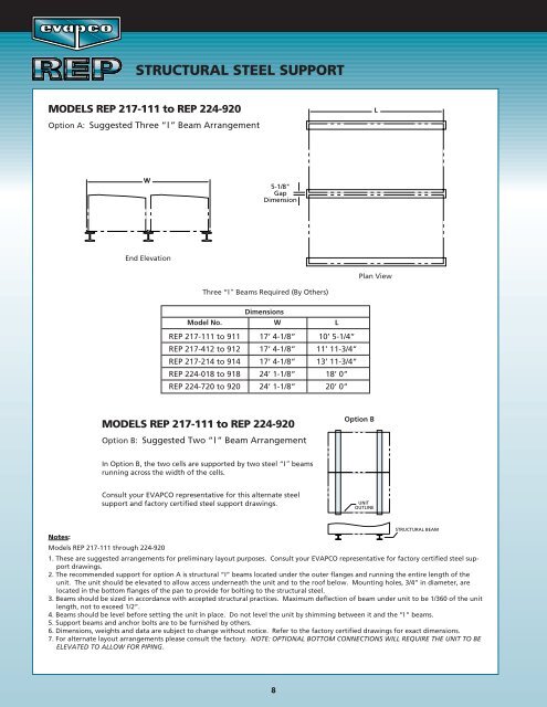
Option A: Suggested Three “I” Beam Arrangement<br />
W<br />
5-1/8"<br />
Gap<br />
Dimension<br />
End Elevation<br />
Plan View<br />
Three “I” Beams Required (By Others)<br />
Dimensions<br />
Model No. W L<br />
<strong>REP</strong> 217-111 to 911 17’ 4-1/8” 10’ 5-1/4”<br />
<strong>REP</strong> 217-412 to 912 17’ 4-1/8” 11’ 11-3/4”<br />
<strong>REP</strong> 217-214 to 914 17’ 4-1/8” 13’ 11-3/4”<br />
<strong>REP</strong> 224-018 to 918 24’ 1-1/8” 18’ 0”<br />
<strong>REP</strong> 224-720 to 920 24’ 1-1/8” 20’ 0”<br />
MODELS <strong>REP</strong> 217-111 to <strong>REP</strong> 224-920<br />
Option B<br />
Option B: Suggested Two “I” Beam Arrangement<br />
In Option B, the two cells are supported by two steel “I” beams<br />
running across the width of the cells.<br />
Consult your EVAPCO representative for this alternate steel<br />
support and factory certified steel support drawings.<br />
UNIT<br />
OUTLINE<br />
STRUCTURAL BEAM<br />
Notes:<br />
Models <strong>REP</strong> 217-111 through 224-920<br />
1. These are suggested arrangements for preliminary layout purposes. Consult your EVAPCO representative for factory certified steel support<br />
drawings.<br />
2. The recommended support for option A is structural “I” beams located under the outer flanges and running the entire length of the<br />
unit. The unit should be elevated to allow access underneath the unit and to the roof below. Mounting holes, 3/4” in diameter, are<br />
located in the bottom flanges of the pan to provide for bolting to the structural steel.<br />
3. Beams should be sized in accordance with accepted structural practices. Maximum deflection of beam under unit to be 1/360 of the unit<br />
length, not to exceed 1/2”.<br />
4. Beams should be level before setting the unit in place. Do not level the unit by shimming between it and the “I” beams.<br />
5. Support beams and anchor bolts are to be furnished by others.<br />
6. Dimensions, weights and data are subject to change without notice. Refer to the factory certified drawings for exact dimensions.<br />
7. For alternate layout arrangements please consult the factory. NOTE: OPTIONAL BOTTOM CONNECTIONS WILL REQUIRE THE UNIT TO BE<br />
ELEVATED TO ALLOW FOR PIPING.<br />
8