
You also want an ePaper? Increase the reach of your titles
YUMPU automatically turns print PDFs into web optimized ePapers that Google loves.
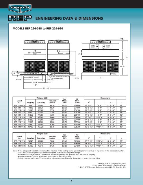
ENGINEERING DATA & DIMENSIONS<br />
MODELS <strong>REP</strong> 224-018 to <strong>REP</strong> 224-920<br />
7"<br />
ACCESS<br />
DOOR<br />
ACCESS<br />
DOOR<br />
(2)10 BFW/GROOVED<br />
INLET<br />
71"<br />
2"<br />
T<br />
H<br />
P<br />
98-1/2"<br />
(2)2 MPT<br />
MAKE-UP<br />
25-1/8"<br />
17"<br />
3-1/2"<br />
96-7/8"<br />
117-7/8"<br />
137-1/4"<br />
(2)3 MPT OVERFLOW<br />
8-1/2"<br />
*(2)10 BFW/GROOVED OUTLET<br />
(2)3 MPT DRAIN<br />
5-1/8"<br />
7/8"<br />
1-3/8"<br />
L<br />
142"<br />
24' 1-1/8"<br />
Weights (LBS)<br />
Dimensions<br />
Fan<br />
Air<br />
Model Heaviest Motor Flow<br />
No. Shipping Operating Section (HP) (CFM) H † T P L<br />
<strong>REP</strong> 224-018 19580 39600 6810 (2) 25 258400 16’ 6-1/2” 8’ 4” 11’ 1-1/4” 18’<br />
<strong>REP</strong> 224-118 19800 39820 6920 (2) 30 274000 16’ 6-1/2” 8’ 4” 11’ 1-1/4” 18’<br />
<strong>REP</strong> 224-218 21140 41160 7590 (2) 25 254100 17’ 6-1/2” 9’ 4” 12’ 1-1/4” 18’<br />
<strong>REP</strong> 224-318 20320 40340 7180 (2) 40 300100 16’ 6-1/2” 8’ 4” 11’ 1-1/4” 18’<br />
<strong>REP</strong> 224-418 21360 41380 7700 (2) 30 269100 17’ 6-1/2” 9’ 4” 12’ 1-1/4” 18’<br />
<strong>REP</strong> 224-518 22840 42860 8440 (2) 30 264800 18’ 6-1/2” ††10’ 4” 13’ 1-1/4” 18’<br />
<strong>REP</strong> 224-618 21880 41900 7960 (2) 40 294400 17’ 6-1/2” 9’ 4” 12’ 1-1/4” 18’<br />
<strong>REP</strong> 224-718 22000 42020 8020 (2) 50 315900 17’ 6-1/2” 9’ 4” 12’ 1-1/4” 18’<br />
<strong>REP</strong> 224-818 23480 43500 8760 (2) 50 310300 18’ 6-1/2” ††10’ 4” 13’ 1-1/4” 18’<br />
<strong>REP</strong> 224-918 23700 43720 8870 (2) 60 328700 18’ 6-1/2” ††10’ 4” 13’ 1-1/4” 18’<br />
Weights (LBS)<br />
Dimensions<br />
Fan<br />
Air<br />
Model Heaviest Motor Flow<br />
No. Shipping Operating Section (HP) (CFM) H † T P L<br />
<strong>REP</strong> 224-720 24840 47200 9260 (2) 40 321200 18’ 6-1/2” ††10’ 4” 13’ 1-1/4” 20’<br />
<strong>REP</strong> 224-820 24960 47320 9320 (2) 50 316000 18’ 6-1/2” ††10’ 4” 13’ 1-1/4” 20’<br />
<strong>REP</strong> 224-920 25180 47540 9430 (2) 60 334800 18’ 6-1/2” ††10’ 4” 13’ 1-1/4” 20’<br />
Note: (1) An adequately sized bleed line must be installed in the cooling tower system to prevent build-up of impurities in the recirculated water.<br />
(2) Do not use catalog drawings for certified prints. Dimensions subject to change.<br />
(3) Connections larger than 3” are Beveled for Welding (BFW) and grooved for a mechanical coupling.<br />
(4) Adequate spacing must be allowed for access to the cooling tower.<br />
(5) Unit can operate as two (2) independent cells with the addition of a flume plate or water tight partition.<br />
† Height does not include fan guard.<br />
†† Fan guard ships loose for field mounting.<br />
* (2)12” BFW/Grooved Outlet on models 224-720 thru 224-920.<br />
6