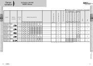
CKD series HLC parallel grippers - BIBUS France
CKD series HLC parallel grippers - BIBUS France
CKD series HLC parallel grippers - BIBUS France

You also want an ePaper? Increase the reach of your titles
YUMPU automatically turns print PDFs into web optimized ePapers that Google loves.
Hand Series<br />
RRC<br />
GRC<br />
RV3*<br />
NHS<br />
HR<br />
LN<br />
FH100<br />
HAP<br />
BSA2<br />
BHA/<br />
BHG<br />
LHA<br />
LHAG<br />
HKP<br />
HLA/<br />
HLB<br />
HLAG/<br />
HLBG<br />
HEP<br />
HCP<br />
HMF<br />
HMFB<br />
HFP<br />
<strong>HLC</strong><br />
HGP<br />
FH500<br />
HBL<br />
HDL<br />
HMD<br />
HJL<br />
BHE<br />
CKG<br />
CK<br />
CKA<br />
CKS<br />
CKF<br />
CKJ<br />
CKL2<br />
CKL2<br />
-*-HC<br />
CKH2<br />
CKLB2<br />
NCK/<br />
SCK/FCK<br />
FJ<br />
FK<br />
Ending<br />
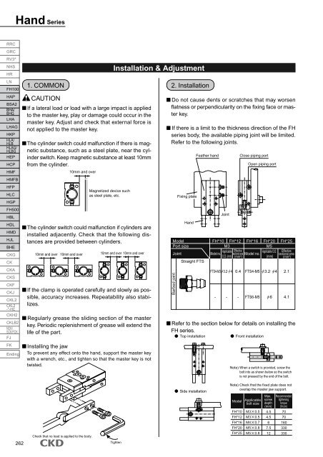
1. COMMON<br />
CAUTION<br />
If a lateral load or load with a large impact is applied<br />
to the master key, play or damage could occur in the<br />
master key. Adjust and check that external force is<br />
not applied to the master key.<br />
The cylinder switch could malfunction if there is magnetic<br />
substance, such as a steel plate, near the cylinder<br />
switch. Keep magnetic substance at least 10mm<br />
from the cylinder.<br />
10mm and over<br />
Magnetized device such<br />
as steel plate, etc.<br />
The cylinder switch could malfunction if cylinders are<br />
installed adjacently. Check that the following distances<br />
are provided between cylinders.<br />
10mm and over<br />
10mm and over<br />
If the clamp is operated carefully and slowly as possible,<br />
accuracy increases. Repeatability also stabilizes.<br />
Regularly grease the sliding section of the master<br />
key. Periodic replenishment of grease will extend the<br />
life of the part.<br />
Installing the jaw<br />
To prevent any effect onto the hand, support the master key<br />
with a wrench, etc., and tighten so that the master key is not<br />
twisted.<br />
Installation & Adjustment<br />
10mm and over 10mm and over<br />
2. Installation<br />
Do not cause dents or scratches that may worsen<br />
flatness or perpendicularity on the fixing face or master<br />
key.<br />
If there is a limit to the thickness direction of the FH<br />
<strong>series</strong> body, the available piping joint will be limited.<br />
Refer to the following joints.<br />
Fixing plate<br />
Hand<br />
Model<br />
Port size<br />
Joint<br />
Barbed joint<br />
Straight FTS<br />
Feather hand<br />
Joint<br />
Close piping port<br />
Open piping port<br />
FH*10 FH*12<br />
M3<br />
FH*16 FH*20<br />
M5<br />
FH*25<br />
Applicable Effective<br />
Applicable O.D. Effective<br />
Model no.<br />
sectional area Model no.<br />
sectional area<br />
O.D. (mm) (mm 2 )<br />
(mm) (mm 2 )<br />
FTS4-M3 3.2· 4 0.4 FTS4-M5 3.2· 4 2.1<br />
- - -<br />
FTS6-M5 6<br />
Refer to the section below for details on installing the<br />
FH <strong>series</strong>.<br />
Top installation<br />
Front installation<br />
4.1<br />
Note) When a switch is provided, screw the<br />
bolt into as shown below so the switch<br />
is not pressed by the end of the bolt.<br />
262<br />
Check that no load is applied to the body.<br />
Tighten<br />
Side installation<br />
Note) Check that the fixed plate does not<br />
overlap the master jaw support.<br />
Model<br />
Applicable<br />
bolt size<br />
FH*10 M3 0.5<br />
FH*12 M3 0.5<br />
FH*16 M4 0.7<br />
FH*20 M5 0.8<br />
FH*25 M5 0.8<br />
Max.<br />
screw<br />
depth<br />
(mm)<br />
4.5<br />
4.5<br />
6<br />
7.5<br />
12<br />
Recommended<br />
tightening<br />
torque<br />
(N·cm)<br />
70<br />
70<br />
160<br />
330<br />
330