W4GB4
W4GB4
W4GB4

Create successful ePaper yourself
Turn your PDF publications into a flip-book with our unique Google optimized e-Paper software.
MN3E0<br />
MN4E0<br />
4GA/B<br />
M4GA/B<br />
MN4GA/B<br />
4GA/B<br />
(Master)<br />
W4GA/B2<br />
<strong>W4GB4</strong><br />
MN3S0<br />
MN4S0<br />
4TB<br />
4L2-4/<br />
LMF0<br />
4SA/B0<br />
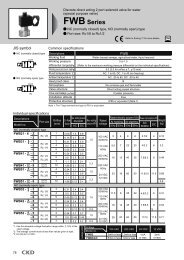
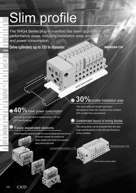
Slim profile<br />
The W4G4 Series plug-in manifold has been upgraded in all<br />
performance areas, including installation area, workability, life,<br />
and power consumption.<br />
Drive cylinders up to 125 in diameter<br />
M<strong>W4GB4</strong>-T10<br />
4SA/B1<br />
4KA/B<br />
4F<br />
PV5G/<br />
CMF<br />
PV5/<br />
CMF<br />
3MA/B0<br />
3PA/B<br />
P/M/B<br />
NP/NAP/<br />
NVP<br />
4F*0E<br />
HMV<br />
HSV<br />
2QV<br />
3QV<br />
SKH<br />
PCD/<br />
FS/FD<br />
Ending<br />
40%<br />
Conventional footprint<br />
lower power consumption<br />
Major energy conservation is realized using a 1 W coil.<br />
(DC specifications)<br />
Easily expanded stations<br />
Connection between the manifold blocks enables valve blocks to be expanded easily without extra work.<br />
Connection between the manifold and<br />
blocks enables valve blocks to be expanded<br />
easily without extra work.<br />
Left specifications (model no.: T10)<br />
W4G4 Series footprint<br />
30%<br />
smaller installation area<br />
The valve width and length have been<br />
decreased to make the manifold more compact,<br />
30% smaller than conventional.<br />
Unrestricted layout of wiring blocks<br />
The wiring block can be selected from the right<br />
(right specifications) or left (left specifications)<br />
of the manifold.<br />
Right specifications (model no.: T10R)<br />
* Photo shows common gland.<br />
524
Upgraded: Operability<br />
Upgraded: Reliability<br />
Upgraded: Safety<br />
Upgraded: Durability<br />
MN3E0<br />
MN4E0<br />
4GA/B<br />
M4GA/B<br />
MN4GA/B<br />
Improved safety and reliability<br />
A rubber cover on the manual button prevents dirt,<br />
etc., from getting caught, eliminating mulfunction.<br />
Rubber cover<br />
Power indicator light<br />
Improved maintenance<br />
The new pilot air OFF function makes it easy to<br />
service and inspect the device.<br />
(M7 option)<br />
Pilot air OFF<br />
4GA/B<br />
(Master)<br />
W4GA/B2<br />
<strong>W4GB4</strong><br />
MN3S0<br />
MN4S0<br />
4TB<br />
4L2-4/<br />
LMF0<br />
4SA/B0<br />
2-color indicator<br />
Greatly extended life<br />
4SA/B1<br />
4KA/B<br />
Orange (solenoid a) and green (solenoid b) are used<br />
for the power lamp.<br />
Ample wire connections<br />
CC-Link, DeviceNet, UNIWIRE, UNIWIRE H, a common<br />
gland, and an I/O cable connector (separate wiring) have<br />
been prepared for serial transmission.<br />
Common gland I/0 connector Serial transmission<br />
CC-Link<br />
UNIWIRE<br />
UNIWIRE H<br />
Life is now even longer with the improved<br />
sliding section and packing, etc.<br />
Protective structure equivalent to IP65<br />
A dust-resistant jet-proof structure equivalent to IP65<br />
is used to enable operation in harsh environments.<br />
RoHS Directive compliant<br />
This eco-friendly design<br />
complies with RoHS Directives.<br />
Improved design<br />
4F<br />
PV5G/<br />
CMF<br />
PV5/<br />
CMF<br />
3MA/B0<br />
3PA/B<br />
P/M/B<br />
NP/NAP/<br />
NVP<br />
4F*0E<br />
HMV<br />
HSV<br />
2QV<br />
3QV<br />
I/O connector<br />
Device Net<br />
CompoBus/S<br />
The new white color provides a refreshing<br />
touch.<br />
SKH<br />
PCD/<br />
FS/FD<br />
Ending<br />
Easy, smooth piping<br />
The pipe coupling is flush with no<br />
protruding valves, so rotating tools such<br />
as wrenches are used easily, improving<br />
piping work efficiency.<br />
Wrench ... A large tool rotation angle is provided.<br />
Plug-in manifold<br />
5 port pilot operated valve<br />
525
Series variation<br />
W4G4 Series<br />
MN3E0<br />
MN4E0<br />
4GA/B<br />
M4GA/B<br />
MN4GA/B<br />
4GA/B<br />
(Master)<br />
W4GA/B2<br />
<strong>W4GB4</strong><br />
MN3S0<br />
MN4S0<br />
4TB<br />
4L2-4/<br />
LMF0<br />
4SA/B0<br />
4SA/B1<br />
4KA/B<br />
4F<br />
PV5G/<br />
CMF<br />
PV5/<br />
CMF<br />
3MA/B0<br />
3PA/B<br />
P/M/B<br />
NP/NAP/<br />
NVP<br />
4F*0E<br />
HMV<br />
HSV<br />
2QV<br />
3QV<br />
SKH<br />
PCD/<br />
FS/FD<br />
Ending<br />
526<br />
Discrete<br />
Sub-base back porting Sub-base side porting<br />
Individual wiring manifold<br />
Reduced wiring manifold<br />
Series variation / appearance<br />
Sub-base side porting<br />
Sub-base back porting<br />
Sub-base side porting<br />
Sub-base back porting<br />
<strong>W4GB4</strong>*0<br />
W4GZ4*0<br />
M<strong>W4GB4</strong>*0<br />
MW4GZ4*0<br />
M<strong>W4GB4</strong>*0<br />
Common gland<br />
(T10)<br />
Serial transmission<br />
(T6*)<br />
MW4GZ4*0<br />
Common gland<br />
(T10)<br />
Serial transmission<br />
(T6*)<br />
I/O connector<br />
(R1)<br />
I/O connector<br />
(R1)<br />
Common gland<br />
(T10R)<br />
Serial transmission<br />
(T6*R)<br />
Common gland<br />
(T10R)<br />
Serial transmission<br />
(T6*R)<br />
M<strong>W4GB4</strong><br />
(N<strong>W4GB4</strong>)<br />
MW4GZ4<br />
(NW4GZ4)<br />
M<strong>W4GB4</strong><br />
(N<strong>W4GB4</strong>)<br />
MW4GZ4<br />
(NW4GZ4)<br />
Model no.<br />
<strong>W4GB4</strong><br />
W4GZ4<br />
Individual wiring<br />
(-R1)<br />
Common gland<br />
Left (-T10)<br />
Right (-T10R)<br />
Serial transmission<br />
Left (-T6*)<br />
Right (-T6*R)<br />
Common gland<br />
Left (-T10)<br />
Right (-T10R)<br />
Serial transmission<br />
Left (-T6*)<br />
Right (-T6*R)<br />
Position<br />
No. of solenoid<br />
JIS symbol<br />
5 port valve<br />
2-position single solenoid<br />
a<br />
4 2<br />
(A) (B)<br />
5 1 3<br />
(R1) (P) (R2)<br />
2-position double solenoid<br />
4 2<br />
a<br />
(A) (B) b<br />
5 1 3<br />
(R1) (P) (R2)<br />
3-position all ports closed<br />
4 2<br />
(A) (B)<br />
a<br />
b<br />
5 1 3<br />
(R1) (P) (R2)<br />
3-position A/B/R connection<br />
4 2<br />
(A) (B)<br />
a<br />
b<br />
5 1 3<br />
(R1) (P) (R2)<br />
3-position P/A/B connection<br />
4 2<br />
(A) (B)<br />
a<br />
b<br />
5 1 3<br />
(R1) (P) (R2)<br />
Valve performance<br />
Flow characteristics C<br />
(dm 3 /<br />
)<br />
Note 1<br />
To<br />
7.3<br />
To<br />
8.3<br />
To<br />
8.3<br />
To<br />
8.3<br />
Applicable cylinder bore size<br />
To<br />
ø125<br />
To<br />
ø125<br />
To<br />
ø125<br />
To<br />
ø125<br />
100<br />
VAC<br />
Voltage<br />
24<br />
VDC<br />
12<br />
VDC<br />
110<br />
VAC<br />
1 3 4 5
W4G4 Series<br />
Series variation<br />
MN3E0<br />
MN4E0<br />
Protective structure<br />
2-position<br />
Single solenoid<br />
Double solenoid<br />
Solenoid position A/B piping port Electric connection<br />
All ports closed<br />
3-position<br />
A/B/R connection<br />
P/A/B connection<br />
Mix<br />
Push-in joint<br />
ø8 ø10 ø12<br />
Note 1: Effective sectional area S and sonic conductance C are converted as S 5.0 x C.<br />
Rc<br />
1/4<br />
Rc<br />
3/8<br />
Female thread<br />
G<br />
1/4<br />
G<br />
3/8<br />
NPT<br />
1/4<br />
NPT<br />
3/8<br />
C8 C10 C12 08 10 08G 10G 08N 10N Blank R1 T10 T6*<br />
Gland<br />
I/O connector<br />
Common gland<br />
Serial transmission<br />
Page<br />
4GA/B<br />
M4GA/B<br />
MN4GA/B<br />
4GA/B<br />
(Master)<br />
W4GA/B2<br />
<strong>W4GB4</strong><br />
MN3S0<br />
MN4S0<br />
IP65 532<br />
4TB<br />
4L2-4/<br />
LMF0<br />
4SA/B0<br />
IP65 532<br />
4SA/B1<br />
4KA/B<br />
4F<br />
IP65 538<br />
PV5G/<br />
CMF<br />
PV5/<br />
CMF<br />
3MA/B0<br />
3PA/B<br />
IP65 538<br />
P/M/B<br />
IP65<br />
IP65<br />
542<br />
NP/NAP/<br />
NVP<br />
4F*0E<br />
HMV<br />
HSV<br />
2QV<br />
3QV<br />
SKH<br />
PCD/<br />
FS/FD<br />
Ending<br />
IP65<br />
IP65<br />
542<br />
Plug-in manifold<br />
5 port pilot operated valve<br />
527
W4G4 Series<br />
MN3E0<br />
MN4E0<br />
4GA/B<br />
Discrete<br />
Electric connection<br />
Individual wiring manifold Reduced wiring manifold<br />
Manual override<br />
(Provided as standard)<br />
Other options<br />
M4GA/B<br />
MN4GA/B<br />
4GA/B<br />
(Master)<br />
W4GA/B2<br />
<strong>W4GB4</strong><br />
MN3S0<br />
MN4S0<br />
4TB<br />
4L2-4/<br />
LMF0<br />
4SA/B0<br />
Blank<br />
R1<br />
Gland<br />
I/O connector<br />
(DC)<br />
Lead wire length<br />
500 mm<br />
R1<br />
I/O connector<br />
(DC)<br />
Lead wire length<br />
500 mm<br />
T10<br />
Common gland<br />
(Left)<br />
Common gland<br />
T10R<br />
(Right)<br />
M Non-locking<br />
Manual override M7 Manual override with<br />
OFF function<br />
Locking<br />
Pilot air OFF<br />
when slide<br />
upwards.<br />
Original position<br />
during normal use.<br />
K External pilot<br />
Individual circuit<br />
specifications of main<br />
pressure and pilot<br />
pressure.<br />
A Coolant proof<br />
Select for measures<br />
against entry of<br />
coolant.<br />
F<br />
A/B port filter<br />
integrated<br />
A/B port filter<br />
Z1 Air supply spacer<br />
Air supply spacer<br />
Z3 Exhaust spacer<br />
Exhaust spacer<br />
4SA/B1<br />
4KA/B<br />
T6*<br />
Serial transmission<br />
(Left)<br />
4F<br />
PV5G/<br />
CMF<br />
PV5/<br />
CMF<br />
3MA/B0<br />
Electric connection circuit diagram (Inside solenoid valve)<br />
With light and surge suppressor (provided as standard)<br />
(~) A<br />
(~) A<br />
SOLa<br />
3PA/B<br />
P/M/B<br />
NP/NAP/<br />
NVP<br />
4F*0E<br />
HMV<br />
HSV<br />
2QV<br />
3QV<br />
Serial transmission<br />
T6*R<br />
(Right)<br />
Single solenoid<br />
AC<br />
(~) COM<br />
( ) A<br />
DC<br />
( ) COM<br />
SOLa<br />
SOLa<br />
Double solenoid<br />
AC (~)<br />
(~)<br />
( )<br />
DC ( )<br />
( )<br />
COM<br />
B<br />
A<br />
COM<br />
B<br />
SOLb<br />
SOLa<br />
SOLb<br />
SKH<br />
PCD/<br />
FS/FD<br />
Ending<br />
528
Pneumatic components<br />
Safety precautions<br />
Always read this section before starting use.<br />
Refer to Intro 63 for precautions of general valves.<br />
5 port pilot operated valve W4G4 Series<br />
1. Working environment<br />
CAUTION<br />
IP65 (IEC60529 (IEC529: 1989-11)) standards are applied to<br />
the test. Avoid use in condition which water or coolant could directly<br />
contact the valve.<br />
Explanation of protection property symbols and examination method of IP65<br />
Protective structure<br />
Note: IP-65 is a standard as followings.<br />
IEC (International Electrotechnical Commission) standards<br />
(IEC60529 (IEC529: 1989-11))<br />
IP-**<br />
Protection property symbols (International Protection)<br />
1st characteristic number (protection grade for foreign solid)<br />
Grade Degree of protection<br />
6<br />
Dust proof type<br />
Powder and dust<br />
do not admit into<br />
the inside.<br />
Design & Selection<br />
3. Surge suppressor<br />
CAUTION<br />
“The surge suppressor enclosed with the solenoid valve is to<br />
protect the output contact for that solenoid valve’s drive. There<br />
is no significant protection for other devices in the area, and<br />
the surge may cause damage or malfunctions. Surge generated<br />
by other devices could be absorbed and cause damage<br />
such as burning. Care must be taken for points below.”<br />
The surge suppressor limits solenoid valve surge voltage, which<br />
can reach several hundred volts, to a lower voltage level withstandable<br />
by the output contact. Depending on the output circuit<br />
used, this may be insufficient and could result in damage or malfunction.<br />
Check whether the surge suppressor can be used by<br />
the surge voltage limit of the solenoid valve in use, the output<br />
device’s withstand pressure and circuit structure, and by the degree<br />
of return delay time. If necessary, provide other surge measures.<br />
Solenoid valves with surge suppressors suppress the reverse<br />
voltage surge generated during OFF operation to the levels<br />
below.<br />
Rated voltage<br />
Reverse voltage value when OFF<br />
12 VDC 27 V<br />
24 VDC 47 V<br />
MN3E0<br />
MN4E0<br />
4GA/B<br />
M4GA/B<br />
MN4GA/B<br />
4GA/B<br />
(Master)<br />
W4GA/B2<br />
<strong>W4GB4</strong><br />
MN3S0<br />
MN4S0<br />
4TB<br />
4L2-4/<br />
LMF0<br />
4SA/B0<br />
4SA/B1<br />
4KA/B<br />
4F<br />
PV5G/<br />
CMF<br />
PV5/<br />
CMF<br />
3MA/B0<br />
3PA/B<br />
2nd characteristic number (Protective class against entry of water)<br />
Grade Degree of protection Overview of test method (fresh water is used)<br />
Protection for jet No harmful effects Using the following test device, spray water for 1<br />
occur even when minute per 1 m 2 of test sample (exterior) surface<br />
water is sprayed a r e a f r o m a l l<br />
12.5 L/min<br />
2.5 to 3 m<br />
with nozzles from directions, for a total<br />
5<br />
all directions. of 3 minutes or more.<br />
2. Alternating current voltage specifications<br />
CAUTION<br />
Spray nozzle I.D. : ø6.3 mm<br />
AC voltage specifications are built into all wave rectification<br />
circuits.<br />
When using SSR to turn the solenoid valve ON and<br />
OFF, solenoid valve recovery could fail. Take care<br />
when selecting the SSR. (Consult with the relay or<br />
PLC manufacturer.)<br />
When using the NPN output unit, a surge voltage equivalent<br />
to the voltage above plus the power voltage surge<br />
could be applied. Provide contact protection circuit.<br />
(Output transistor protection circuit parallel setting example 1)<br />
Programmable<br />
controller side<br />
(Output transistor protection circuit parallel setting example 2)<br />
Programmable<br />
controller side<br />
Solenoid valve side<br />
Solenoid valve side<br />
P/M/B<br />
NP/NAP/<br />
NVP<br />
4F*0E<br />
HMV<br />
HSV<br />
2QV<br />
3QV<br />
SKH<br />
PCD/<br />
FS/FD<br />
Ending<br />
Plug-in manifold<br />
5 port pilot operated valve<br />
529
W4G4 Series<br />
MN3E0<br />
MN4E0<br />
4GA/B<br />
M4GA/B<br />
MN4GA/B<br />
4GA/B<br />
(Master)<br />
W4GA/B2<br />
<strong>W4GB4</strong><br />
MN3S0<br />
MN4S0<br />
4TB<br />
4L2-4/<br />
LMF0<br />
4SA/B0<br />
If another device or solenoid valve is connected in parallel to the solenoid<br />
valve, reverse voltage surge generated when the solenoid valve is<br />
off is applied to these devices. Even when using the solenoid valve with<br />
a 24 VDC surge suppressor, the surge voltage could reach several tens<br />
of volts depending on the model. This revere polarity voltage could damage<br />
devices connected in parallel or cause them to malfunction. Avoid<br />
parallel connection of devices suspected of reversing polarity voltages,<br />
e.g., LED indicators. When driving several solenoid valves in parallel,<br />
the surge from other solenoid valves could enter the surge suppressor<br />
of one solenoid valve with a surge suppressor. Depending on the current<br />
value, that surge suppressor could burn. When driving several solenoid<br />
valves with surge suppressors in parallel, surge current could concentrate<br />
at the surge suppressor with the lowest limit voltage and cause<br />
similar burning. Even if the solenoid valve type is the same, the surge<br />
suppressor’s limit voltage can be inconsistent, and in the worst case,<br />
could result in burning. Avoid driving several solenoid valves in parallel.<br />
Design & Selection<br />
Installation & Adjustment<br />
The surge suppressor incorporated in the solenoid valve often<br />
short-circuits if damaged by overvoltage or overcurrent from a<br />
source other than the solenoid valve. If the surge suppressor<br />
fails, if a large current flows when output is on, the output circuit<br />
or solenoid valve could be damaged or ignite. Do not keep power<br />
on in a faulty state. Provide an overcurrent protection circuit<br />
on the power or drive circuit or use a power supply with overcurrent<br />
protection so that a large current does not flow continuously.<br />
4. Partition plug<br />
When using partition plug, consult with CKD sales<br />
office.<br />
4SA/B1<br />
4KA/B<br />
4F<br />
PV5G/<br />
CMF<br />
PV5/<br />
CMF<br />
3MA/B0<br />
3PA/B<br />
P/M/B<br />
NP/NAP/<br />
NVP<br />
4F*0E<br />
HMV<br />
HSV<br />
2QV<br />
3QV<br />
SKH<br />
PCD/<br />
FS/FD<br />
Ending<br />
1. Common<br />
CAUTION<br />
Port indication<br />
Port positions such as 1P and 4A, etc., are indicated in accordance<br />
with ISO and JIS standards.<br />
Applications ISO standards JIS standards<br />
Supply port 1 P<br />
Output port 4 A<br />
Output port 2 B<br />
Exhaust port 5 R1<br />
Exhaust port 3 R2<br />
Pilot air supplying port 12/14 PA<br />
Pilot exhaust port 82/84 PR<br />
Any valve mounting attitude is permissible. Check the port<br />
symbol to pipe as a reverse action such as cylinder, etc., is<br />
not created.<br />
2. Port filter<br />
CAUTION<br />
Port filter is used to prevent foreign materials from<br />
entering, and problems in a valve. This is not for improving<br />
quality of compressed air, so read the warning<br />
and the cautions in the Introduction very well,<br />
then implement installation and adjustment.<br />
Do not remove or force the port filter.<br />
The filter could deform and result in problems. If<br />
contaminants and foreign materials are found on<br />
the filter surface, flash lightly, or remove them by<br />
tweezers, etc.<br />
Example of integrating A/B port filter<br />
For female thread type<br />
Filter<br />
Filter<br />
530<br />
For cartridge joint
During Use & Maintenance<br />
1. Valve replacement 3. How to replace cartridge joint<br />
W4G4 Series<br />
Precautions<br />
MN3E0<br />
MN4E0<br />
4GA/B<br />
CAUTION<br />
Check that the gasket does not fall off when replacing<br />
and installing the valve.<br />
Hexagonal wrench Proper tightening<br />
Mounting bolt Thread size<br />
size torque (N m)<br />
Hexagon socket head bolt M4 Nominal 3 2.4 to 2.6<br />
2. Pilot air OFF function (M7)<br />
CAUTION<br />
The supply of pilot air is forcibly stopped when power<br />
is on, so the main valve can be switched even<br />
when power is on.<br />
When using the OFF function, caution is required because<br />
the cylinder moves immediately when using the 2-position<br />
single and 3-position A/B/R connection or P/A/B connection.<br />
Output port destination list<br />
Solenoid position<br />
OFF function (energized side M7 switch) De-energized side manual<br />
No operation Operation (OFF) Operation<br />
2-position Single solenoid a side sol. energizing 4 (A) 2 (B) -<br />
Double solenoid<br />
a side sol. energizing 4 (A) 4 (A) 2 (B)<br />
b side sol. energizing 2 (B) 2 (B) 4 (A)<br />
3-position All ports a side sol. energizing 4 (A) 4 (A) 2 (B)<br />
closed b side sol. energizing 2 (B) 2 (B) 4 (A)<br />
A/B/R connection<br />
a side sol. energizing 4 (A) - 2 (B)<br />
b side sol. energizing 2 (B) - 4 (A)<br />
P/A/B connection<br />
a side sol. energizing 4 (A) 4 (A)/2 (B) 2 (B)<br />
b side sol. energizing 2 (B) 4 (A)/2 (B) 4 (A)<br />
How to operate M7 switch<br />
1 When using OFF function<br />
Slide the M7 switch in the direction of the arrow until it<br />
stops.<br />
This is a lock switch, so the OFF function is not reset even<br />
if the switch is released.<br />
CAUTION<br />
Check procedures before changing the push-in joint size.<br />
Problems such as air leakage could occur if the joint is not<br />
installed properly or if mounting threads are not tightened<br />
sufficiently.<br />
1<br />
2<br />
3<br />
4<br />
Joint stop plate<br />
Set screw<br />
Remove the set screw.<br />
Pull out the joint stopper plate and joint together.<br />
Align the stopper plate with the groove on the replacement joint, and assemble temporarily.<br />
Assemble the stopper plate and joint together, and tighten the<br />
set screw. Pull on the joint to confirm that it is properly installed.<br />
(Tightening torque: 0.55 to 0.65 Nm)<br />
Cartridge type push-in joint model no.<br />
Model Part name Model no.<br />
W4G4 ø8 straight 4G4-JOINT-C8<br />
ø10 straight<br />
4G4-JOINT-C10<br />
ø12 straight<br />
4G4-JOINT-C12<br />
M4GA/B<br />
MN4GA/B<br />
4GA/B<br />
(Master)<br />
W4GA/B2<br />
<strong>W4GB4</strong><br />
MN3S0<br />
MN4S0<br />
4TB<br />
4L2-4/<br />
LMF0<br />
4SA/B0<br />
4SA/B1<br />
4KA/B<br />
4F<br />
PV5G/<br />
CMF<br />
PV5/<br />
CMF<br />
3MA/B0<br />
3PA/B<br />
P/M/B<br />
NP/NAP/<br />
NVP<br />
4F*0E<br />
HMV<br />
HSV<br />
2QV<br />
3QV<br />
SKH<br />
PCD/<br />
FS/FD<br />
Ending<br />
2<br />
During normal use<br />
Return the M7 switch to the original position.<br />
WARNING<br />
When conducting manual operations, make sure that there<br />
are no people near the moving cylinder.<br />
Plug-in manifold<br />
5 port pilot operated valve<br />
531
MN3E0<br />
MN4E0<br />
4GA/B<br />
M4GA/B<br />
Discrete<br />
sub-base side porting and back porting<br />
<strong>W4GB4</strong>/W4GZ4 Series<br />
Applicable cylinder bore size: ø63 to ø125<br />
Refer to Intro 17 for<br />
(Subject: DC voltage) details.<br />
MN4GA/B<br />
Common specifications<br />
4GA/B<br />
(Master) Descriptions<br />
<strong>W4GB4</strong>/W4GZ4<br />
W4GA/B2<br />
Type of valve / operation method Pilot operated soft spool valve<br />
Working fluid<br />
Compressed air<br />
<strong>W4GB4</strong><br />
Max. working pressure MPa 1.0<br />
Min. working pressure MPa 0.2<br />
MN3S0 Withstanding pressure MPa 1.50<br />
MN4S0<br />
Ambient temperature °C<br />
-5 to 55 (no freezing)<br />
4TB Fluid temperature °C 5 to 55<br />
4L2-4/<br />
Manual override<br />
Non-locking type (standard)<br />
LMF0 Lubrication Note 1 Not required<br />
4SA/B0<br />
Protective structure Note 2 Dust proof / jet-proof (IP65 or equivalent)<br />
Vibration / impact m/s 2 49 or less / 294 or less<br />
4SA/B1 Working environment Containing corrosive gas is impermissible.<br />
4KA/B<br />
4F<br />
PV5G/<br />
CMF<br />
PV5/<br />
CMF<br />
3MA/B0<br />
3PA/B<br />
P/M/B<br />
NP/NAP/<br />
NVP<br />
4F*0E<br />
HMV<br />
HSV<br />
2QV<br />
3QV<br />
SKH<br />
PCD/<br />
FS/FD<br />
Ending<br />
Note 1: Use the turbine oil Class 1 ISO VG32 if lubricated.<br />
Excessive lubrication results in instable operation.<br />
Note 2: IP65 (IEC60529 (IEC529: 1989-11)) standards are applied to the test.<br />
Refer to page 529 for details.<br />
Note 3: The working pressure range is 0 to 1.0 MPa when the external pilot<br />
(option symbol: K) is selected.Set the external pilot pressure between 0.2<br />
to 1.0 MPa.<br />
JIS symbol<br />
5 port valve<br />
2-position single solenoid<br />
4 2<br />
a<br />
(A) (B)<br />
5 1 3<br />
(R1) (P) (R2)<br />
2-position double solenoid<br />
4 2<br />
a<br />
(A) (B) b<br />
5 1 3<br />
(R1) (P) (R2)<br />
3-position all ports closed<br />
4 2<br />
(A) (B)<br />
a<br />
b<br />
5 1 3<br />
(R1) (P) (R2)<br />
3-position A/B/R connection<br />
4 2<br />
(A) (B)<br />
a<br />
b<br />
5 1 3<br />
(R1) (P) (R2)<br />
3-position P/A/B connection<br />
4 2<br />
(A) (B)<br />
a<br />
b<br />
5 1 3<br />
(R1) (P) (R2)<br />
Individual specifications<br />
Port size<br />
Flow characteristics<br />
Electric specifications<br />
Descriptions<br />
<strong>W4GB4</strong>/W4GZ4<br />
Rated voltage DC 12, 24<br />
V AC<br />
100 (50/60Hz)<br />
110 (50/60Hz)<br />
Rated voltage fluctuation range 10%<br />
Holding current 12 VDC 0.100<br />
24 VDC 0.050<br />
A<br />
100 VAC 0.024<br />
110 VAC 0.024<br />
Power consumption 12 VDC 1.2<br />
Note 4 W 24 VDC 1.2<br />
Apparent power 100 VAC 2.4<br />
VA 110 VAC 2.6<br />
Heat proof class<br />
B (molded coil)<br />
Note 4: Surge suppressor and indicator are provided as standard.<br />
Descriptions <strong>W4GB4</strong> W4GZ4<br />
P/A/B port<br />
R port<br />
Rc1/4, Rc3/8, G1/4,<br />
G3/8, NPT1/4, NPT3/8<br />
Rc1/4, Rc3/8, G1/4, G3/8,<br />
NPT1/4, NPT3/8<br />
Rc1/4, G1/4, NPT1/4<br />
PA/PR port Rc1/8, G1/8, NPT1/8 Rc1/8, G1/8, NPT1/8<br />
Descriptions<br />
<strong>W4GB4</strong>/W4GZ4<br />
When ON<br />
When OFF<br />
Response time 2-position Single solenoid 30 38<br />
ms<br />
Double solenoid 30 -<br />
3-position A/B/R connection 50 58<br />
Response time is the value at supply pressure 0.5 MPa, 20°C and oilless. The value will change based on quality of pressure and oil.<br />
Descriptions Gland I/O connector<br />
Weight g 2-position Single solenoid 701 755<br />
Double solenoid 745 799<br />
3-position All ports closed 777 831<br />
P → A/B<br />
A/B → R<br />
Model no. Solenoid position<br />
C (dm 3 / (s bar)) b C (dm 3 / (s bar)) b<br />
2-position 7.7 0.31 7.3 0.16<br />
All ports closed 6.6 0.19 6.4 0.21<br />
<strong>W4GB4</strong><br />
3-position A/B/R connection 6.5 0.15 7.3 0.04<br />
P/A/B connection 7.4 0.21 7.1 0.16<br />
Note 1: Effective sectional area S and sonic conductance C are converted as S 5.0 x C.<br />
Note 2: Flow characteristics are values for port size Rc3/8.<br />
Coolant proof specifications<br />
532<br />
Can be selected with "E" option "A" in How to Order on Page 533.
How to order<br />
Discrete<br />
<strong>W4GB4</strong> 3 0 10 R1 MF 3<br />
W4GZ4 3 0 10 R1 M7 3<br />
Only discrete sub-plate<br />
<strong>W4GB4</strong> SP 10 R1<br />
W4GZ4 SP 10 R1<br />
A Model no.<br />
B Solenoid position<br />
Note on selection guide<br />
C Port size<br />
Note 1: 3(R2) and 5(R1) ports are Rc1/4 for back porting.<br />
Note 2: 3(R2) and 5(R1) ports are G1/4 for back porting.<br />
Note 3: 3(R2) and 5(R1) ports are NPT1/4 for back<br />
porting.<br />
Note 4: Voltage is only DC specifications for an I/O<br />
connector.<br />
Note 5: Select either "M" or "M7".<br />
Note 6: Both lock equipment with non-locking manual<br />
override and pilot air OFF function are provided.<br />
D Electric connection<br />
Electric connection<br />
Name Gland I/O connector (DC)<br />
Symbol Blank R1<br />
M12 4 pin<br />
Male (plug)<br />
Shape<br />
Terminal<br />
arrangement<br />
Sub-plate<br />
B COM A<br />
K<br />
K<br />
E Option<br />
3: COM<br />
(PNP)<br />
<strong>W4GB4</strong>/W4GZ4 Series<br />
Discrete valve: Sub-base side porting and back porting<br />
F Voltage<br />
2: B 1: COM<br />
(NPN)<br />
4: A<br />
Symbol Descriptions<br />
B Solenoid position<br />
1 2-position single solenoid<br />
2 2-position double solenoid<br />
3 3-position all ports closed<br />
4 3-position A/B/R connection<br />
5 3-position P/A/B connection<br />
Discrete<br />
W<br />
4<br />
G<br />
B<br />
4<br />
A Model no.<br />
W<br />
4<br />
G<br />
Z<br />
4<br />
Only discrete<br />
sub-plate<br />
C Port size {1(P), 2(B), 4(A) port}<br />
08 Rc1/4 Note 1 Note 1<br />
10 Rc3/8 Note 1 Note 1<br />
08G G1/4 Note 2 Note 2<br />
10G G3/8 Note 2 Note 2<br />
08N NPT1/4 Note 3 Note 3<br />
10N NPT3/8 Note 3 Note 3<br />
D Electric connection (light and surge suppressor provided as standard)<br />
Blank Gland<br />
R1 I/O connector (500 mm for DC) Note 4<br />
E Option<br />
M Non-locking (standard) Note 5<br />
M7 Lock with pilot air OFF Note 5, Note 6<br />
K External pilot<br />
A Coolant proof<br />
F A/B port filter<br />
F Voltage<br />
1 100 VAC<br />
3 24 VDC<br />
4 12 VDC<br />
5 110 VAC<br />
is not available.<br />
Kit model no. for gland type<br />
Cable clamp (with gasket)<br />
Model no.<br />
W4G-OA-W1608C1<br />
G1/2<br />
Gasket<br />
W<br />
4<br />
G<br />
B<br />
4<br />
W<br />
4<br />
G<br />
Z<br />
4<br />
Descriptions<br />
This is used to protect a cable<br />
from dust and jet.<br />
Applicable cable O.D.<br />
Applicable cable outer diameter : ø6 to ø8<br />
(Reference value)<br />
Cable clamp body tightening torque: 2.0 to 2.4 N m<br />
Tightening cap tightening torque : 0.5 to 0.7 N m<br />
21<br />
533<br />
MN3E0<br />
MN4E0<br />
4GA/B<br />
M4GA/B<br />
MN4GA/B<br />
4GA/B<br />
(Master)<br />
W4GA/B2<br />
<strong>W4GB4</strong><br />
MN3S0<br />
MN4S0<br />
4TB<br />
4L2-4/<br />
LMF0<br />
4SA/B0<br />
4SA/B1<br />
4KA/B<br />
4F<br />
PV5G/<br />
CMF<br />
PV5/<br />
CMF<br />
3MA/B0<br />
3PA/B<br />
P/M/B<br />
NP/NAP/<br />
NVP<br />
4F*0E<br />
HMV<br />
HSV<br />
2QV<br />
3QV<br />
SKH<br />
PCD/<br />
FS/FD<br />
Ending<br />
Plug-in manifold<br />
5 port pilot operated valve
<strong>W4GB4</strong>/W4GZ4 Series<br />
Discrete valve: Sub-base side porting and back porting<br />
MN3E0<br />
MN4E0<br />
4GA/B<br />
Dimensions<br />
<strong>W4GB4</strong>10<br />
Gland (blank)<br />
Side porting<br />
128.5<br />
M4GA/B<br />
MN4GA/B<br />
2-Rc1/4 or Rc3/8<br />
4 (A), 2 (B) port<br />
74.5<br />
49.5<br />
4GA/B<br />
(Master)<br />
25<br />
30.5<br />
W4GA/B2<br />
<strong>W4GB4</strong><br />
MN3S0<br />
MN4S0<br />
4TB<br />
4L2-4/<br />
LMF0<br />
4SA/B0<br />
2-ø5.5<br />
(Installation hole)<br />
149.5<br />
103<br />
75 15<br />
4SA/B1<br />
4KA/B<br />
38<br />
55<br />
4F<br />
Manual override section<br />
Light display<br />
PV5G/<br />
CMF<br />
PV5/<br />
CMF<br />
3MA/B0<br />
G1/2<br />
Wiring outlet<br />
Rc1/8<br />
82/84 (PR) port<br />
104<br />
3PA/B<br />
P/M/B<br />
30.2<br />
30.5<br />
NP/NAP/<br />
NVP<br />
4F*0E<br />
3-Rc1/4 or Rc3/8<br />
5 (R1), 1 (P), 3 (R2) port<br />
24 24<br />
39 62<br />
14.5<br />
HMV<br />
HSV<br />
2QV<br />
3QV<br />
SKH<br />
W4GZ410<br />
Gland (blank)<br />
Back porting<br />
PCD/<br />
FS/FD<br />
Ending<br />
2-Rc1/4<br />
5 (R1), 3 (R2) port<br />
25.5<br />
25.5<br />
62<br />
13<br />
26.5<br />
3-Rc1/4 or Rc3/8<br />
1 (P), 4 (A), 2 (B) port<br />
25<br />
49.5<br />
534
<strong>W4GB4</strong>/W4GZ4 Series<br />
Discrete valve: Sub-base side porting and back porting<br />
Dimensions<br />
<strong>W4GB4</strong>20<br />
Gland (blank)<br />
Side porting<br />
128.5<br />
MN3E0<br />
MN4E0<br />
4GA/B<br />
2-Rc1/4 or Rc3/8<br />
4 (A), 2 (B) port<br />
74.5<br />
49.5<br />
M4GA/B<br />
MN4GA/B<br />
25<br />
30.5<br />
4GA/B<br />
(Master)<br />
W4GA/B2<br />
<strong>W4GB4</strong><br />
MN3S0<br />
MN4S0<br />
2-ø5.5<br />
(Installation hole)<br />
149.5<br />
86<br />
17<br />
75 15<br />
7<br />
4TB<br />
4L2-4/<br />
LMF0<br />
4SA/B0<br />
<br />
38<br />
55<br />
4SA/B1<br />
4KA/B<br />
2-manual override section<br />
2-light display<br />
4F<br />
G1/2<br />
Wiring outlet<br />
Rc1/8<br />
82/84 (PR) port<br />
104<br />
PV5G/<br />
CMF<br />
PV5/<br />
CMF<br />
3MA/B0<br />
3PA/B<br />
30.2<br />
30.5<br />
P/M/B<br />
3-Rc1/4 or Rc3/8<br />
5 (R1), 1 (P), 3 (R2) port<br />
24 24<br />
39 62<br />
14.5<br />
NP/NAP/<br />
NVP<br />
4F*0E<br />
W4GZ420<br />
Gland (blank)<br />
Back porting<br />
HMV<br />
HSV<br />
2QV<br />
3QV<br />
SKH<br />
2-Rc1/4<br />
5 (R1), 3 (R2) port<br />
25.5<br />
62<br />
25.5<br />
PCD/<br />
FS/FD<br />
Ending<br />
3-Rc1/4 or Rc3/8<br />
1 (P), 4 (A), 2 (B) port<br />
25<br />
49.5<br />
26.5<br />
13<br />
Plug-in manifold<br />
5 port pilot operated valve<br />
535
<strong>W4GB4</strong>/W4GZ4 Series<br />
Discrete valve: Sub-base side porting and back porting<br />
MN3E0<br />
MN4E0<br />
4GA/B<br />
M4GA/B<br />
MN4GA/B<br />
Dimensions<br />
3<br />
5<br />
Gland (blank)<br />
W4GB<br />
4<br />
0<br />
Side porting<br />
2-Rc1/4 or Rc3/8<br />
4 (A), (B) port<br />
128.5<br />
74.5<br />
49.5<br />
4GA/B<br />
(Master)<br />
25<br />
30.5<br />
W4GA/B2<br />
<strong>W4GB4</strong><br />
MN3S0<br />
MN4S0<br />
4TB<br />
4L2-4/<br />
LMF0<br />
4SA/B0<br />
4SA/B1<br />
2-ø5.5<br />
(Installation hole)<br />
149.5<br />
7<br />
86<br />
17<br />
75 15<br />
4KA/B<br />
<br />
38<br />
55<br />
4F<br />
PV5G/<br />
CMF<br />
PV5/<br />
CMF<br />
3MA/B0<br />
3PA/B<br />
G1/2<br />
Wiring outlet<br />
2-manual override section<br />
Rc1/8<br />
82/84 (PR) port<br />
2-light display<br />
104<br />
P/M/B<br />
NP/NAP/<br />
NVP<br />
4F*0E<br />
30.2<br />
3-Rc1/4 or Rc3/8<br />
5 (R1), 1 (P), 3 (R2) port<br />
24 24<br />
14.5<br />
30.5<br />
HMV<br />
HSV<br />
2QV<br />
3QV<br />
SKH<br />
3<br />
W4GZ<br />
4<br />
0<br />
5<br />
Gland (blank)<br />
Back porting<br />
39 62<br />
PCD/<br />
FS/FD<br />
Ending<br />
2-Rc1/4<br />
5 (R1), 3 (R2) port<br />
25.5<br />
62<br />
25.5<br />
13<br />
26.5<br />
3-Rc1/4 or Rc3/8<br />
1 (P), 4 (A), 2 (B) port<br />
25<br />
49.5<br />
536
<strong>W4GB4</strong>/W4GZ4 Series<br />
Discrete valve: Sub-base side porting and back porting<br />
Dimensions<br />
With pilot air OFF function (M7)<br />
MN3E0<br />
MN4E0<br />
4GA/B<br />
M4GA/B<br />
MN4GA/B<br />
2-Rc1/4 or Rc3/8<br />
4 (A), 2 (B) port<br />
74.5<br />
49.5<br />
4GA/B<br />
(Master)<br />
25<br />
30.5<br />
W4GA/B2<br />
<strong>W4GB4</strong><br />
MN3S0<br />
MN4S0<br />
4TB<br />
2-ø5.5<br />
(Installation hole)<br />
149.5<br />
86 17<br />
75 15<br />
7<br />
4L2-4/<br />
LMF0<br />
4SA/B0<br />
<br />
38<br />
55<br />
4SA/B1<br />
2-manual override section<br />
2-light display<br />
4KA/B<br />
Pilot air OFF function switch (locking)<br />
a side<br />
Rc1/8<br />
82/84 (PR) port<br />
G1/2<br />
Wiring outlet<br />
104<br />
Pilot air OFF function switch (locking)<br />
b side<br />
4F<br />
PV5G/<br />
CMF<br />
PV5/<br />
CMF<br />
3MA/B0<br />
30.2<br />
3-Rc1/4 or Rc3/8<br />
5 (R1), 1 (P), 3 (R2) port<br />
24 24<br />
39 62<br />
14.5<br />
30.5<br />
3PA/B<br />
P/M/B<br />
NP/NAP/<br />
NVP<br />
4F*0E<br />
External pilot (K) I/O connector (R1)<br />
Cable: VA-4DBXO5KUG3-CKD276-PG7 (CORRENS)<br />
HMV<br />
HSV<br />
2QV<br />
3QV<br />
SKH<br />
34.5<br />
Rc1/8<br />
12/14 (PA) port<br />
32.4<br />
(475)<br />
Connector with cable M12<br />
4 pin male (plug)<br />
PCD/<br />
FS/FD<br />
Ending<br />
Plug-in manifold<br />
5 port pilot operated valve<br />
537
MN3E0<br />
MN4E0<br />
4GA/B<br />
M4GA/B<br />
Individual wiring manifold<br />
Sub-base side porting and back porting<br />
B<br />
MW4G Z 4-R1 Series<br />
Applicable cylinder bore size: ø63 to ø125<br />
Refer to Intro 17 for<br />
(Subject: DC voltage) details.<br />
MN4GA/B<br />
Common specifications<br />
4GA/B<br />
(Master) Descriptions M<strong>W4GB4</strong> MW4GZ4<br />
W4GA/B2<br />
Manifold type<br />
Block manifold<br />
Air supply and exhaust method Common supply and common exhaust<br />
<strong>W4GB4</strong><br />
Pilot exhaust method Main valve and pilot valve individual exhaust<br />
Piping direction Sub-base side porting Sub-base bottom porting<br />
MN3S0 Type of valve / operation method Pilot operated soft spool valve<br />
MN4S0<br />
Working fluid<br />
Compressed air<br />
4TB Max. working pressure MPa 1.0<br />
4L2-4/<br />
Min. working pressure MPa 0.2<br />
LMF0 Withstanding pressure MPa 1.5<br />
4SA/B0<br />
Ambient temperature °C<br />
-5 to 55 (no freezing)<br />
Fluid temperature °C 5 to 55<br />
4SA/B1 Manual override<br />
Non-locking<br />
Lubrication Note 1 Not required<br />
4KA/B Protective structure Note 2 Dust proof / jet-proof (IP65 or equivalent)<br />
Vibration / impact m/s 2 49 or less / 294 or less<br />
4F Working environment Containing corrosive gas is impermissible.<br />
PV5G/<br />
CMF<br />
PV5/<br />
CMF<br />
3MA/B0<br />
3PA/B<br />
P/M/B<br />
NP/NAP/<br />
NVP<br />
4F*0E<br />
HMV<br />
HSV<br />
2QV<br />
3QV<br />
SKH<br />
PCD/<br />
FS/FD<br />
Ending<br />
538<br />
Note 1: Use the turbine oil Class 1 ISO VG32 if lubricated.<br />
Excessive lubrication results in instable operation.<br />
Note 2: IP65 (IEC60529 (IEC529: 1989-11)) standards are applied to the test.<br />
Refer to page 529 for details.<br />
Note 3: The working pressure range is 0 to 1.0 MPa when the external pilot<br />
(option symbol: K) is selected.Set the external pilot pressure between<br />
0.2 to 1.0 MPa.<br />
JIS symbol<br />
5 port valve<br />
2-position single solenoid<br />
4 2<br />
a<br />
(A) (B)<br />
5 1 3<br />
(R1) (P) (R2)<br />
2-position double solenoid<br />
4 2<br />
a<br />
(A) (B) b<br />
5 1 3<br />
(R1) (P) (R2)<br />
3-position all ports closed<br />
4 2<br />
(A) (B)<br />
a<br />
b<br />
5 1 3<br />
(R1) (P) (R2)<br />
3-position A/B/R connection<br />
4 2<br />
(A) (B)<br />
a<br />
b<br />
5 1 3<br />
(R1) (P) (R2)<br />
3-position P/A/B connection<br />
4 2<br />
(A) (B)<br />
a<br />
b<br />
5 1 3<br />
(R1) (P) (R2)<br />
Individual specifications<br />
Flow characteristics<br />
Electric specifications<br />
Descriptions<br />
M<strong>W4GB4</strong>/MW4GZ4<br />
Rated voltage V DC 12, 24<br />
Rated voltage fluctuation range 10%<br />
Holding current A 12 VDC 0.100<br />
24 VDC 0.050<br />
Power consumption W 12 VDC 1.2<br />
Note 4 24 VDC 1.2<br />
Heat proof class<br />
B (molded coil)<br />
Wiring method<br />
I/O connector (for DC)<br />
Note 4: Surge suppressor and indicator are provided as standard.<br />
Descriptions M<strong>W4GB4</strong> MW4GZ4<br />
Maximum station number 16<br />
Port size<br />
P port<br />
Rc1/4, Rc3/8, G1/4,<br />
Rc1/2, G1/2, NPT1/2<br />
A/B port G3/8, NPT1/4, NPT3/8, Rc1/4, G1/4, NPT1/4<br />
R port<br />
PA/PR port<br />
Descriptions<br />
Push-in joint ø8, ø10, ø12<br />
Rc1/2, G1/2, NPT1/2<br />
Rc1/8, G1/8, NPT1/8<br />
M<strong>W4GB4</strong>/MW4GZ4<br />
When ON<br />
When OFF<br />
Response time ms 2-position Single solenoid 30 38<br />
Double solenoid 30 -<br />
3-position A/B/R connection 50 58<br />
Response time is the value at supply pressure 0.5 MPa, 20°C and oilless. The value will change based on quality of pressure and oil.<br />
Model no.<br />
<strong>W4GB4</strong><br />
Solenoid position<br />
P → A/B<br />
A/B → R<br />
C (dm 3 / (s bar)) b C (dm 3 / (s bar)) b<br />
2-position 7.4 0.24 7.9 0.30<br />
All ports closed 6.4 0.22 7.1 0.32<br />
3-position A/B/R connection 6.4 0.17 8.3 0.28<br />
P/A/B connection 7.1 0.16 7.4 0.28<br />
Note 1: Effective sectional area S and sonic conductance C are converted as S 5.0 x C.<br />
Note 2: Flow characteristics are values for port size Rc3/8.<br />
Coolant proof specifications<br />
Can be selected with "E" option "A" in How to Order on page 539.
How to order<br />
Manifold model no.<br />
M<strong>W4GB4</strong> 8 0 10 R1 M 6<br />
MW4GZ4 8 0 08<br />
Individual wiring I/O connector<br />
R1<br />
M<br />
B<br />
MW4G Z 4-R1 Series<br />
Individual wiring manifold: Sub-base side porting and back porting<br />
3<br />
6 3<br />
A Model no.<br />
Discrete valve block<br />
Manifold<br />
with solenoid valve<br />
Discrete<br />
solenoid valve<br />
MN3E0<br />
MN4E0<br />
4GA/B<br />
M4GA/B<br />
Discrete valve block with solenoid valve<br />
N<strong>W4GB4</strong><br />
NW4GZ4<br />
Discrete solenoid valve<br />
A Model no.<br />
1 0 10 R1 M7 3<br />
1 0 08N R1 M7 4<br />
<strong>W4GB4</strong> 1 9 00 M 3<br />
B Solenoid<br />
position<br />
C Port size<br />
D Electric connection<br />
Symbol Descriptions<br />
B Solenoid position<br />
1 2-position single solenoid<br />
2 2-position double solenoid<br />
3 3-position all ports closed<br />
4 3-position A/B/R connection<br />
5 3-position P/A/B connection<br />
8 Mix manifold<br />
C Port size {2 (B), 4 (A) port }<br />
08 Rc1/4<br />
10 Rc3/8<br />
08G G1/4<br />
10G G3/8<br />
08N NPT1/4<br />
10N NPT3/8<br />
C8 ø8 push-in<br />
C10 ø10 push-in<br />
C12 ø12 push-in<br />
D Electric connection (light and surge suppressor provided as standard)<br />
R1 I/O connector (500 mm)<br />
M<br />
W<br />
4<br />
G<br />
B<br />
4<br />
M<br />
W<br />
4<br />
G<br />
Z<br />
4<br />
N<br />
W<br />
4<br />
G<br />
B<br />
4<br />
N<br />
W<br />
4<br />
G<br />
Z<br />
4<br />
W<br />
4<br />
G<br />
B<br />
4<br />
MN4GA/B<br />
4GA/B<br />
(Master)<br />
W4GA/B2<br />
<strong>W4GB4</strong><br />
MN3S0<br />
MN4S0<br />
4TB<br />
4L2-4/<br />
LMF0<br />
4SA/B0<br />
4SA/B1<br />
4KA/B<br />
4F<br />
PV5G/<br />
CMF<br />
PV5/<br />
CMF<br />
3MA/B0<br />
Note on selection guide<br />
Fill out "manifold specifications".<br />
Note 1: Select either "M" or "M7".<br />
Note 2: Both lock equipment with non-locking manual<br />
override and pilot air OFF function are provided.<br />
Note 3: Instruct spacer installation position and quantity<br />
with the manifold specifications.<br />
Refer to page 559 for the details.<br />
Note 4: This is common for internal and external pilot.<br />
Note 5: A filter to prevent entry of foreign matter is<br />
incorporated in end block 1 (P) port as standard.<br />
E Option<br />
F Station number<br />
G Voltage<br />
E Option<br />
M Non-locking (standard) Note 1<br />
M7 Lock with pilot air OFF Note 1, Note 2<br />
Z1 Air supply spacer Note 3<br />
Z3 Exhaust spacer Note 3<br />
K External pilot Note 4 Note 4 Note 4<br />
A Coolant proof<br />
F A/B port filter Note 5<br />
F Station number<br />
1 1 station<br />
to to<br />
16 16 stations<br />
G Voltage<br />
3 24 VDC<br />
4 12 VDC<br />
is not available.<br />
3PA/B<br />
P/M/B<br />
NP/NAP/<br />
NVP<br />
4F*0E<br />
HMV<br />
HSV<br />
2QV<br />
3QV<br />
SKH<br />
PCD/<br />
FS/FD<br />
Ending<br />
Plug-in manifold<br />
5 port pilot operated valve<br />
539
MN3E0<br />
MN4E0<br />
4GA/B<br />
M4GA/B<br />
B<br />
MW4G Z 4-R1 Series<br />
Individual wiring manifold: Sub-base side porting and back porting<br />
Manifold components explanation and parts list<br />
Valve set screw<br />
5<br />
MN4GA/B<br />
4<br />
4GA/B<br />
(Master)<br />
W4GA/B2<br />
Tie rod set screw<br />
<strong>W4GB4</strong><br />
Gasket<br />
MN3S0<br />
MN4S0<br />
Tie rod<br />
4TB<br />
4L2-4/<br />
LMF0<br />
4SA/B0<br />
3<br />
4SA/B1<br />
4KA/B<br />
4F<br />
PV5G/<br />
CMF<br />
PV5/<br />
CMF<br />
3MA/B0<br />
3PA/B<br />
P/M/B<br />
NP/NAP/<br />
NVP<br />
4F*0E<br />
HMV<br />
HSV<br />
2QV<br />
3QV<br />
SKH<br />
PCD/<br />
FS/FD<br />
Ending<br />
1<br />
Main parts list (refer to pages 552 to 559 for details.)<br />
No. Component name Model no. (example) No. Component name Model no. (example)<br />
1 End block L NW4G4-EL 4 Discrete solenoid valve <strong>W4GB4</strong>19-00-M-3<br />
2 Discrete valve block N<strong>W4GB4</strong>-V-10-R1 5 End block R NW4G4-ER<br />
3 Discrete valve block with solenoid valve N<strong>W4GB4</strong>10-10-R1M-3<br />
Component weight (DC specifications)<br />
Component Weight Component Weight<br />
End block NW4G4-EL 316 Discrete valve block with masking plate N<strong>W4GB4</strong>-MP-10-R1 415<br />
NW4G4-ER 308 NW4GZ4-MP-08-R1 448<br />
Discrete valve block with solenoid valve N<strong>W4GB4</strong>10-10-R1M-3 584 Tie rod W4G4-TR-V1 (2 pcs. set) 16<br />
N<strong>W4GB4</strong>20-10-R1M-3 629 W4G4-TR-V2 (2 pcs. set) 36<br />
N<strong>W4GB4</strong>30-10-R1M-3 661 Tie rod set screw (2 pcs.) 16<br />
NW4GZ410-08-R1M-3 617<br />
NW4GZ420-08-R1M-3 662<br />
NW4GZ430-08-R1M-3 694<br />
Repair parts and related parts list<br />
No. Parts name Model no.<br />
- Cartridge type ø8 straight 4G4-JOINT-C8<br />
push-in joint and ø10 straight 4G4-JOINT-C10<br />
related parts ø12 straight 4G4-JOINT-C12<br />
Blanking plug<br />
Gasket<br />
2<br />
For ø8: GWP8-B, for ø10: GWP10-B,<br />
for ø12: GWP12-B<br />
(g)<br />
540
Dimensions<br />
M<strong>W4GB4</strong> Side porting<br />
I/O connector (R1)<br />
B<br />
MW4G Z 4-R1 Series<br />
Individual wiring manifold: Sub-base side porting and back porting<br />
Cable: VA-4DBXO5KUG3-CKD276-PG7 (CORRENS)<br />
MN3E0<br />
MN4E0<br />
4GA/B<br />
M4GA/B<br />
MN4GA/B<br />
Connector with cable M12<br />
4 pin male (plug)<br />
6.5<br />
L2=25n+76<br />
L1=25n+63<br />
38 25 25 25 38<br />
122<br />
40.6<br />
18.6<br />
4GA/B<br />
(Master)<br />
W4GA/B2<br />
<strong>W4GB4</strong><br />
(480)<br />
(20)<br />
4-R4.5<br />
(Installation hole)<br />
134<br />
106<br />
10<br />
9<br />
<br />
Light display<br />
Manual<br />
override section<br />
122.5 (single solenoid)<br />
134 (double solenoid)<br />
152 (3-position)<br />
2-Rc1/8<br />
82/84 (PR) port<br />
20.3<br />
6-Rc1/2<br />
5 (R1), 1 (P), 3 (R2) port<br />
21<br />
21<br />
37.6<br />
48<br />
65<br />
For K (external pilot)<br />
2-Rc1/8<br />
12/14 (PA) port<br />
MN3S0<br />
MN4S0<br />
4TB<br />
4L2-4/<br />
LMF0<br />
4SA/B0<br />
4SA/B1<br />
4KA/B<br />
4F<br />
PV5G/<br />
CMF<br />
PV5/<br />
CMF<br />
59<br />
27.6<br />
76<br />
3MA/B0<br />
Push-in joint for valve block<br />
ø8 (C8) ø10 (C10) ø12 (C12)<br />
15<br />
MW4GZ4<br />
I/O connector (R1)<br />
Back porting<br />
17<br />
10.5<br />
50.5<br />
21<br />
2n-Rc1/4,Rc3/8,C8,C10,C12<br />
4 (A), 2 (B) port<br />
23<br />
3PA/B<br />
P/M/B<br />
NP/NAP/<br />
NVP<br />
4F*0E<br />
HMV<br />
HSV<br />
2QV<br />
3QV<br />
SKH<br />
PCD/<br />
FS/FD<br />
Ending<br />
2n-Rc1/4<br />
4 (A), 2 (B) port<br />
24 57.2<br />
44<br />
Plug-in manifold<br />
5 port pilot operated valve<br />
541
MN3E0<br />
MN4E0<br />
4GA/B<br />
M4GA/B<br />
Reduced wiring manifold<br />
sub-base side porting and back porting<br />
B<br />
MW4G Z 4-T1/6 Series<br />
Applicable cylinder bore size: ø63 to ø125<br />
Refer to Intro 17 for<br />
(Subject: DC voltage) details.<br />
MN4GA/B<br />
Common specifications<br />
4GA/B<br />
(Master) Descriptions M<strong>W4GB4</strong> MW4GZ4<br />
W4GA/B2<br />
Manifold type<br />
Block manifold<br />
Air supply and exhaust method Common supply and common exhaust<br />
<strong>W4GB4</strong><br />
Pilot exhaust method Main valve and pilot valve individual exhaust<br />
Piping direction Sub-base side porting Sub-base bottom porting<br />
MN3S0 Type of valve / operation method Pilot operated soft spool valve<br />
MN4S0<br />
Working fluid<br />
Compressed air<br />
4TB Max. working pressure MPa 1.0<br />
4L2-4/<br />
Min. working pressure MPa 0.2<br />
LMF0 Withstanding pressure MPa 1.5<br />
4SA/B0<br />
Ambient temperature °C<br />
-5 to 55 (no freezing)<br />
Fluid temperature °C 5 to 55<br />
4SA/B1 Manual override<br />
Non-locking<br />
Lubrication Note 1 Not required<br />
4KA/B Protective structure Note 2 Dust proof / jet-proof (IP65 or equivalent)<br />
Vibration / impact m/s 2 49 or less / 294 or less<br />
4F Working environment Containing corrosive gas is impermissible.<br />
PV5G/<br />
CMF<br />
PV5/<br />
CMF<br />
3MA/B0<br />
3PA/B<br />
P/M/B<br />
NP/NAP/<br />
NVP<br />
4F*0E<br />
HMV<br />
HSV<br />
2QV<br />
3QV<br />
SKH<br />
PCD/<br />
FS/FD<br />
Ending<br />
Electric specifications<br />
Descriptions<br />
Note 1: Use the turbine oil Class 1 ISO VG32 if lubricated.Excessive lubrication results in instable operation.<br />
Note 2: IP65 (IEC60529 (IEC529: 1989-11)) standards are applied to the test. Refer to page 529 for details.<br />
Note 3: The working pressure range<br />
JIS symbol<br />
5 port valve<br />
2-position single solenoid<br />
4 2<br />
a<br />
(A) (B)<br />
5 1 3<br />
(R1) (P) (R2)<br />
2-position double solenoid<br />
4 2<br />
a<br />
(A) (B) b<br />
5 1 3<br />
(R1) (P) (R2)<br />
3-position all ports closed<br />
4 2<br />
(A) (B)<br />
a<br />
b<br />
5 1 3<br />
(R1) (P) (R2)<br />
3-position A/B/R connection<br />
4 2<br />
(A) (B)<br />
a<br />
b<br />
5 1 3<br />
(R1) (P) (R2)<br />
3-position P/A/B connection<br />
4 2<br />
(A) (B)<br />
a<br />
b<br />
5 1 3<br />
(R1) (P) (R2)<br />
Individual specifications<br />
Maximum station number<br />
Descriptions<br />
Flow characteristics<br />
M<strong>W4GB4</strong>/MW4GZ4<br />
Rated voltage DC 12, 24<br />
V AC<br />
100 (50/60Hz)<br />
Note 4<br />
110 (50/60Hz)<br />
Rated voltage fluctuation range 10%<br />
Holding current 12 VDC 0.100<br />
24 VDC 0.050<br />
A<br />
100 VAC 0.024<br />
110 VAC 0.024<br />
Power consumption W 12 VDC 1.2<br />
Note 5 24 VDC 1.2<br />
Apparent power VA 100 VAC 2.4<br />
110 VAC 2.6<br />
Heat proof class<br />
B (molded coil)<br />
Note 4: Serial transmission connection is used only with 24 VDC .<br />
Note 5: Surge suppressor and indicator are provided as standard.<br />
M<strong>W4GB4</strong><br />
MW4GZ4<br />
T10 (R) T6*1 (R) T10 (R) T6*1 (R)<br />
Common gland Serial transmission Common gland Serial transmission<br />
Standard wiring 16<br />
Double wiring 8<br />
Maximum solenoid number 16<br />
Port size<br />
P port<br />
Rc1/4, Rc3/8, G1/4,<br />
Rc1/2, G1/2, NPT1/2<br />
A/B port G3/8, NPT1/4, NPT3/8, Rc1/4, G1/4, NPT1/4<br />
R port<br />
PA/PR port<br />
Descriptions<br />
Push-in joint ø8, ø10, ø12<br />
Rc1/2, G1/2, NPT1/2<br />
Rc1/8, G1/8, NPT1/8<br />
M<strong>W4GB4</strong>/MW4GZ4<br />
When ON<br />
When OFF<br />
Response time ms 2-position Single solenoid 30 38<br />
Double solenoid 30 -<br />
3-position A/B/R connection 50 58<br />
Response time is the value at supply pressure 0.5 MPa, 20°C and oilless. The value will change based on quality of pressure and oil.<br />
Model no.<br />
<strong>W4GB4</strong><br />
Solenoid position<br />
P → A/B<br />
A/B → R<br />
C (dm 3 / (s bar)) b C (dm 3 / (s bar)) b<br />
2-position 7.4 0.24 7.9 0.30<br />
All ports closed 6.4 0.22 7.1 0.32<br />
3-position A/B/R connection 6.4 0.17 8.3 0.28<br />
P/A/B connection 7.1 0.16 7.4 0.28<br />
Note 1: Effective sectional area S and sonic conductance C are converted as S 5.0 x C.<br />
Note 2: Flow characteristics are values for port size Rc3/8.<br />
542
B<br />
MW4G Z 4-T1/6 Series<br />
Reduced wiring manifold: Sub-base side porting and back porting<br />
Serial transmission slave unit specifications (refer to page 569 for the applicable PLC table.)<br />
Descriptions T6D1 (R) Note 1 T6G1 (R) T6A1 (R) T6J1 (R) T6C1 (R)<br />
Network name DeviceNet CC-Link ver1.10 UNIWIRE SYSTEM UNIWIRE H SYSTEM CompoBus/S<br />
Unit side 24 VDC 10% 24 VDC 24 VDC 10%<br />
Power voltage<br />
Valve side 24 VDC +10%, -5% +10%, -5% (power supply terminal common) 24 VDC +10%, -5%<br />
100 mA or less 200 mA or less 150 mA or less 60 mA or less<br />
Current Unit side<br />
(Output when all points ON)<br />
Output when all points ON Output when all points ON (Output when all points ON)<br />
consumption<br />
Valve side 15 mA or less (when all points OFF) (Current consumption of body not included) (Current consumption of body not included) 15 mA or less (when all points OFF)<br />
Output no. 16 points 16 points 16 points 16 points 16 points<br />
Note 1: Consult with CKD for EDS file. (EDS file: Text file of parameters for communicating with each company's master.)<br />
Coolant proof specifications<br />
Can be selected with "G", "F" option "A" in How to Order on pages 544 and 545.<br />
MN3E0<br />
MN4E0<br />
4GA/B<br />
M4GA/B<br />
MN4GA/B<br />
4GA/B<br />
(Master)<br />
W4GA/B2<br />
<strong>W4GB4</strong><br />
MN3S0<br />
MN4S0<br />
4TB<br />
4L2-4/<br />
LMF0<br />
4SA/B0<br />
4SA/B1<br />
4KA/B<br />
4F<br />
PV5G/<br />
CMF<br />
PV5/<br />
CMF<br />
3MA/B0<br />
3PA/B<br />
P/M/B<br />
NP/NAP/<br />
NVP<br />
4F*0E<br />
HMV<br />
HSV<br />
2QV<br />
3QV<br />
SKH<br />
PCD/<br />
FS/FD<br />
Ending<br />
Plug-in manifold<br />
5 port pilot operated valve<br />
543
MN3E0<br />
MN4E0<br />
4GA/B<br />
M4GA/B<br />
B<br />
MW4G Z 4-T1 Series<br />
Reduced wiring manifold: Sub-base side porting and back porting<br />
How to order<br />
Manifold model no.<br />
M<strong>W4GB4</strong> 8 0 10 T10 W M 6<br />
MW4GZ4<br />
8 0 08 T10R W M 6 3<br />
3<br />
A<br />
Manifold<br />
Model no.<br />
Discrete valve block<br />
with solenoid valve<br />
Discrete<br />
solenoid<br />
valve<br />
MN4GA/B<br />
4GA/B<br />
(Master)<br />
W4GA/B2<br />
<strong>W4GB4</strong><br />
MN3S0<br />
MN4S0<br />
4TB<br />
4L2-4/<br />
LMF0<br />
4SA/B0<br />
4SA/B1<br />
4KA/B<br />
4F<br />
PV5G/<br />
CMF<br />
PV5/<br />
CMF<br />
3MA/B0<br />
3PA/B<br />
P/M/B<br />
NP/NAP/<br />
NVP<br />
4F*0E<br />
HMV<br />
HSV<br />
2QV<br />
3QV<br />
SKH<br />
PCD/<br />
FS/FD<br />
Discrete valve block with solenoid valve<br />
N<strong>W4GB4</strong><br />
NW4GZ4<br />
Discrete solenoid valve<br />
<strong>W4GB4</strong><br />
A Model no.<br />
1 0 10 1 M7 1<br />
1 0 08N 1 M7 4<br />
1 9 00<br />
M 3<br />
B Solenoid<br />
position<br />
C Port size<br />
Note on selection guide<br />
Fill out "manifold specifications".<br />
D Electric connection<br />
Ending Note 1: <strong>W4GB4</strong>*9: Plug-in connector<br />
NW4G*4*0: Electric wire for relay (AC)<br />
Connector for relay (DC)<br />
Note 2: Standard wiring ... Wired based on the installed<br />
valve.<br />
Double wiring ... Double-solenoid wiring used<br />
regardless of installed valve.<br />
Note 3: Select either "M" or "M7".<br />
Note 4: Both lock devices with non-locking manual<br />
override and pilot air OFF function are provided.<br />
Note 5: Instruct spacer installation position and quantity<br />
with the manifold specifications.<br />
Refer to page 559 for the details.<br />
Note 6: This is common for internal and external pilot.<br />
Note 7: A filter to prevent entry of foreign matter is<br />
incorporated in end block 1 (P) port as standard.<br />
Note 8: The maximum number of MF stations is 16 with<br />
standard wiring and 8 with double wiring.<br />
544<br />
E Wiring method<br />
F Terminal and connector<br />
pin array<br />
G Option<br />
H Station number<br />
I<br />
Voltage<br />
Symbol Descriptions<br />
B Solenoid position<br />
1 2-position single solenoid<br />
2 2-position double solenoid<br />
3 3-position all ports closed<br />
4 3-position A/B/R connection<br />
5 3-position P/A/B connection<br />
8 Mix manifold<br />
C Port size {2 (B), 4 (A) port }<br />
08 Rc1/4<br />
10 Rc3/8<br />
08G G1/4<br />
10G G3/8<br />
08N NPT1/4<br />
10N NPT3/8<br />
C8 ø8 push-in<br />
C10 ø10 push-in<br />
C12 ø12 push-in<br />
D Electric connection<br />
Blank Reduced wiring DC specifications<br />
1 Common gland AC spec. 1 to 6th sta.<br />
2 Common gland AC spec. 7 to 12th sta.<br />
3 Common gland AC spec. 13 to 16th sta.<br />
M<br />
W<br />
4<br />
G<br />
B<br />
4<br />
M<br />
W<br />
4<br />
G<br />
Z<br />
4<br />
N<br />
W<br />
4<br />
G<br />
B<br />
4<br />
N<br />
W<br />
4<br />
G<br />
Z<br />
4<br />
E Wiring method (light and surge suppressor provided as standard)<br />
Blank Discrete Note 1<br />
T10<br />
Common gland<br />
Left<br />
T10R<br />
Right<br />
F Terminal and connector pin array<br />
Blank Standard wiring Note 2<br />
W Double wiring Note 2<br />
G Option<br />
M Non-locking (standard) Note 3<br />
M7 Lock with pilot air OFF Note 3, Note 4<br />
Z1 Air supply spacer Note 5<br />
Z3 Exhaust spacer Note 5<br />
K External pilot Note 6 Note 6 Note 6<br />
A Coolant proof<br />
F A/B port filter Note 7<br />
H Station number<br />
1 1 station<br />
to to<br />
16 16 stations<br />
I Voltage<br />
1 100 VAC<br />
3 24 VDC<br />
4 12 VDC<br />
5 110 VAC<br />
is not available.<br />
Note 8 Note 8<br />
W<br />
4<br />
G<br />
B<br />
4
How to order<br />
Manifold model no.<br />
M<strong>W4GB4</strong> 8 0 10 T6G1 W M 6<br />
MW4GZ4<br />
8 0 08 T6D1R W M 6<br />
B<br />
MW4G Z 4-T6 Series<br />
Reduced wiring manifold: Sub-base side porting and back porting<br />
3<br />
3<br />
Manifold<br />
A Model no.<br />
Discrete valve block<br />
with solenoid valve<br />
Discrete<br />
solenoid<br />
valve<br />
MN3E0<br />
MN4E0<br />
4GA/B<br />
M4GA/B<br />
Discrete valve block with solenoid valve<br />
N<strong>W4GB4</strong><br />
NW4GZ4<br />
Discrete solenoid valve<br />
<strong>W4GB4</strong><br />
A Model no.<br />
1 0 10<br />
M7<br />
1 0 08N<br />
M7<br />
1 9 00<br />
M<br />
B Solenoid<br />
position<br />
C Port size<br />
Note on selection guide<br />
Fill out "manifold specifications".<br />
Note 1: <strong>W4GB4</strong>*9: Plug-in connector<br />
NW4G*4*0: Electric wire for relay (AC)<br />
Connector for relay (DC)<br />
Note 2: Standard wiring ... Wired based on the installed<br />
valve.<br />
Double wiring ... Double-solenoid wiring used<br />
regardless of installed valve.<br />
Note 3: Select either "M" or "M7".<br />
Note 4: Both lock devices with non-locking manual override and<br />
pilot air OFF function are provided.<br />
Note 5: Instruct spacer installation position and quantity with<br />
the manifold specifications.<br />
Refer to page 559 for the details.<br />
Note 6: This is common for internal and external pilot.<br />
Note 7: For slave unit (OPP2), standard specifications are<br />
different from coolant proof specifications.<br />
Option Slave unit cover material Specifications<br />
Standard Polycarbonate Spatter proof<br />
A Nylon Coolant proof<br />
Note 8: A filter to prevent entry of foreign matter is<br />
incorporated in end block 1 (P) port as standard.<br />
Note 9: The maximum number of MF stations is 16 with<br />
standard wiring and 8 with double wiring.<br />
Note 10: 100/110 VAC and 12 VDC settings are not<br />
used for serial transmission connection<br />
specifications.<br />
D Wiring method<br />
E Terminal and connector<br />
pin array<br />
F Option<br />
3<br />
3<br />
3<br />
H Voltage<br />
G Station number<br />
Symbol Descriptions<br />
B Solenoid position<br />
1 2-position single solenoid<br />
2 2-position double solenoid<br />
3 3-position all ports closed<br />
4 3-position A/B/R connection<br />
5 3-position P/A/B connection<br />
8 Mix manifold<br />
C Port size {2 (B), 4 (A) port }<br />
08 Rc1/4<br />
10 Rc3/8<br />
08G G1/4<br />
10G G3/8<br />
08N NPT1/4<br />
10N NPT3/8<br />
C8 ø8 push-in<br />
C10 ø10 push-in<br />
C12 ø12 push-in<br />
M<br />
W<br />
4<br />
G<br />
B<br />
4<br />
M<br />
W<br />
4<br />
G<br />
Z<br />
4<br />
N<br />
W<br />
4<br />
G<br />
B<br />
4<br />
N<br />
W<br />
4<br />
G<br />
Z<br />
4<br />
D Wiring method (light and surge suppressor provided as standard)<br />
Blank Discrete Note 1<br />
T6G1 Serial transmission Left<br />
T6G1R CC-Link 16 points Right<br />
T6J1 Serial transmission Left<br />
T6J1R UNIWIRE H 16 points Right<br />
T6A1 Serial transmission Left<br />
T6A1R UNIWIRE 16 points Right<br />
T6D1 Serial transmission Left<br />
T6D1R DeviceNet 16 points Right<br />
T6C1 Serial transmission Left<br />
T6C1R CompoBus/S 16 points Right<br />
E Terminal and connector pin array<br />
Blank Standard wiring Note 2<br />
W Double wiring Note 2<br />
F Option<br />
M Non-locking (standard) Note 3<br />
M7 Lock with pilot air OFF Note 3, Note 4<br />
Z1 Air supply spacer Note 5<br />
Z3 Exhaust spacer Note 5<br />
K External pilot Note 6 Note 6 Note 6<br />
A Coolant proof Note 7<br />
F A/B port filter Note 8<br />
G Station number<br />
1 1 station<br />
to to<br />
16 16 stations<br />
H Voltage<br />
3 24 VDC Note 10<br />
is not available.<br />
Note 9 Note 9<br />
W<br />
4<br />
G<br />
B<br />
4<br />
545<br />
MN4GA/B<br />
4GA/B<br />
(Master)<br />
W4GA/B2<br />
<strong>W4GB4</strong><br />
MN3S0<br />
MN4S0<br />
4TB<br />
4L2-4/<br />
LMF0<br />
4SA/B0<br />
4SA/B1<br />
4KA/B<br />
4F<br />
PV5G/<br />
CMF<br />
PV5/<br />
CMF<br />
3MA/B0<br />
3PA/B<br />
P/M/B<br />
NP/NAP/<br />
NVP<br />
4F*0E<br />
HMV<br />
HSV<br />
2QV<br />
3QV<br />
SKH<br />
PCD/<br />
FS/FD<br />
Ending<br />
Plug-in manifold<br />
5 port pilot operated valve
MN3E0<br />
MN4E0<br />
4GA/B<br />
B<br />
MW4G Z 4-T1/6 Series<br />
Reduced wiring manifold: Sub-base side porting and back porting<br />
Manifold components explanation and parts list<br />
M4GA/B<br />
MN4GA/B<br />
Valve set screw<br />
4GA/B<br />
(Master)<br />
W4GA/B2<br />
<strong>W4GB4</strong><br />
MN3S0<br />
MN4S0<br />
Gasket<br />
The configuration shown below<br />
applies for the AC type.<br />
5<br />
Tie rod<br />
6<br />
Tie rod set screw<br />
4TB<br />
4L2-4/<br />
LMF0<br />
4SA/B0<br />
The drawing is for<br />
gland type.<br />
2<br />
3<br />
4<br />
4SA/B1<br />
4KA/B<br />
4F<br />
PV5G/<br />
CMF<br />
PV5/<br />
CMF<br />
3MA/B0<br />
3PA/B<br />
1<br />
Gasket<br />
P/M/B<br />
NP/NAP/<br />
NVP<br />
4F*0E<br />
HMV<br />
HSV<br />
2QV<br />
3QV<br />
SKH<br />
PCD/<br />
FS/FD<br />
Ending<br />
Main parts list (refer to pages 552 to 559 for details.)<br />
No. Component name Model no. (example) No. Component name Model no. (example)<br />
1 End block L NW4G4-EL 4 Discrete valve block with solenoid valve N<strong>W4GB4</strong>10-10-M-3<br />
2 Wiring block NW4G4-T10 5 Discrete solenoid valve <strong>W4GB4</strong>19-00-M-3<br />
3 Discrete valve block N<strong>W4GB4</strong>-V1-10 6 End block R NW4G4-ER<br />
Component weight (DC specifications)<br />
Block type Weight Block type Weight<br />
End block NW4G4-EL 316 Discrete valve block with masking plate N<strong>W4GB4</strong>-MPD-10 360<br />
NW4G4-ER 308 NW4GZ4-MPD-08 393<br />
Discrete valve block with solenoid valve N<strong>W4GB4</strong>10-10-M-3 527 Wiring block NW4G4-T10 550<br />
N<strong>W4GB4</strong>20-10-M-3 573 NW4G4-T6G1 710<br />
N<strong>W4GB4</strong>30-10-M-3 605 Tie rod W4G4-TR-V1 (2 pcs. set) 16<br />
NW4GZ410-08-M-3 560 W4G4-TR-V2 (2 pcs. set) 36<br />
NW4GZ420-08-M-3 606 Tie rod set screw (2 pcs.) 16<br />
NW4GZ430-08-M-3 638<br />
(g)<br />
546
Repair parts and related parts list<br />
No. Parts name Model no.<br />
- Cartridge type ø8 straight 4G4-JOINT-C8<br />
push-in joint and ø10 straight 4G4-JOINT-C10<br />
related parts ø12 straight 4G4-JOINT-C12<br />
Blanking plug<br />
Kit for wiring block T10<br />
Cable clamp<br />
Model no. Applicable cable O.D. Descriptions<br />
B<br />
MW4G Z 4-T1/6 Series<br />
Reduced wiring manifold: Sub-base side porting and back porting<br />
For ø8: GWP8-B, for ø10: GWP10-B,<br />
for ø12: GWP12-B<br />
W4G-SCL-18A ø14.5 to 16.5 This is used to protect a cable<br />
W4G-SCL-18B ø16.5 to 18.5 from dust and jet.<br />
G3/4<br />
Gasket<br />
38<br />
36<br />
Kit for wiring block T6*<br />
Cable clamp<br />
Model no. Applicable cable O.D. Descriptions<br />
W4G-OA-W1608C1 ø6 to 8 This is used to protect a cable from dust and jet.<br />
G1/2<br />
Gasket<br />
21<br />
MN3E0<br />
MN4E0<br />
4GA/B<br />
M4GA/B<br />
MN4GA/B<br />
4GA/B<br />
(Master)<br />
W4GA/B2<br />
<strong>W4GB4</strong><br />
MN3S0<br />
MN4S0<br />
4TB<br />
4L2-4/<br />
LMF0<br />
4SA/B0<br />
max. 29.5<br />
max. 40<br />
(Reference value)<br />
Body tightening torque : 4.0 to 4.5 N m<br />
Cable clamp tightening torque : 3.0 to 3.5 N m<br />
Applicable cable O.D.<br />
Applicable cable outer diameter : ø6 to ø8<br />
(Reference value)<br />
Body tightening torque : 2.0 to 2.4 N m<br />
Cable clamp tightening torque : 0.5 to 0.7 N m<br />
4SA/B1<br />
4KA/B<br />
4F<br />
PV5G/<br />
CMF<br />
PV5/<br />
CMF<br />
3MA/B0<br />
3PA/B<br />
P/M/B<br />
NP/NAP/<br />
NVP<br />
4F*0E<br />
HMV<br />
HSV<br />
2QV<br />
3QV<br />
SKH<br />
PCD/<br />
FS/FD<br />
Ending<br />
Plug-in manifold<br />
5 port pilot operated valve<br />
Applicable cable O.D.<br />
547
MN3E0<br />
MN4E0<br />
4GA/B<br />
M4GA/B<br />
MN4GA/B<br />
4GA/B<br />
(Master)<br />
B<br />
MW4G Z 4-T1/6 Series<br />
Reduced wiring manifold: Sub-base side porting and back porting<br />
Dimensions<br />
M<strong>W4GB4</strong><br />
Common gland (T10) Left<br />
Side porting<br />
W4GA/B2<br />
<strong>W4GB4</strong><br />
MN3S0<br />
MN4S0<br />
4TB<br />
4L2-4/<br />
LMF0<br />
4SA/B0<br />
4SA/B1<br />
4KA/B<br />
4F<br />
PV5G/<br />
CMF<br />
PV5/<br />
CMF<br />
3MA/B0<br />
3PA/B<br />
P/M/B<br />
NP/NAP/<br />
NVP<br />
4F*0E<br />
HMV<br />
HSV<br />
2QV<br />
3QV<br />
SKH<br />
PCD/<br />
FS/FD<br />
Ending<br />
Push-in joint for valve block<br />
ø8 (C8) ø10 (C10) ø12 (C12)<br />
15<br />
MW4GZ4<br />
Common gland (T10) Left<br />
134<br />
106<br />
10<br />
6.5<br />
9<br />
2-G3/4<br />
Wiring outlet (1 plug attached)<br />
110.5<br />
81<br />
59<br />
27.6<br />
10.5<br />
17<br />
Back porting<br />
L2=25n+126<br />
L1=25n+113<br />
88 25 25 Manual<br />
override<br />
4-R4.5<br />
(Installation hole)<br />
34.5<br />
100.5<br />
21<br />
Light<br />
indicator<br />
25 38<br />
2n-Rc1/4,Rc3/8,C8,C10,C12<br />
4 (A), 2 (B) port<br />
122.5 (single solenoid)<br />
76<br />
134 (double solenoid)<br />
152 (3-position)<br />
2-Rc1/8<br />
82/84 (PR)<br />
port<br />
23<br />
122<br />
40.6<br />
18.6<br />
20.3<br />
For K (external pilot)<br />
2-Rc1/8<br />
12/14 (PA) port<br />
6-Rc1/2<br />
5 (R1), 1 (P),<br />
3 (R2) port<br />
21<br />
21<br />
37.6<br />
48<br />
65<br />
94<br />
2n-Rc1/4<br />
4 (A), 2 (B) port<br />
24 57.2<br />
548
Dimensions<br />
M<strong>W4GB4</strong> Side porting<br />
Common gland (T10R) Right<br />
B<br />
MW4G Z 4-T1/6 Series<br />
Reduced wiring manifold: Sub-base side porting and back porting<br />
MN3E0<br />
MN4E0<br />
4GA/B<br />
M4GA/B<br />
MN4GA/B<br />
4GA/B<br />
(Master)<br />
6.5<br />
L2=25n+126<br />
L1=25n+113<br />
38 25 25 M.-override section<br />
25<br />
88<br />
122<br />
40.6<br />
18.6<br />
W4GA/B2<br />
<strong>W4GB4</strong><br />
134<br />
106<br />
9<br />
Light indicator<br />
122.5 (single solenoid)<br />
134 (double solenoid)<br />
152 (3-position)<br />
6-Rc1/2<br />
5 (R1), 1 (P),<br />
3 (R2) port<br />
21<br />
21<br />
37.6<br />
48<br />
65<br />
MN3S0<br />
MN4S0<br />
4TB<br />
4L2-4/<br />
LMF0<br />
4SA/B0<br />
10<br />
4-R4.5<br />
(Installation hole)<br />
2-Rc1/8<br />
82/84 (PR) port<br />
20.3<br />
For K (external pilot)<br />
2-Rc1/8<br />
12/14 (PA) port<br />
4SA/B1<br />
4KA/B<br />
4F<br />
2-G3/4<br />
Wiring outlet (1 plug attached)<br />
PV5G/<br />
CMF<br />
PV5/<br />
CMF<br />
75<br />
17 27.6<br />
10.5<br />
59<br />
81<br />
110.5<br />
3MA/B0<br />
3PA/B<br />
Push-in joint for valve block<br />
ø8 (C8) ø10 (C10) ø12 (C12)<br />
15<br />
50.5<br />
2n-Rc1/4,Rc3/8,C8,C10,C12<br />
4 (A), 2 (B) port<br />
21<br />
34.6<br />
23<br />
P/M/B<br />
NP/NAP/<br />
NVP<br />
4F*0E<br />
HMV<br />
HSV<br />
2QV<br />
3QV<br />
SKH<br />
PCD/<br />
FS/FD<br />
MW4GZ4 Back porting<br />
Common gland (T10R) Right<br />
24 57.2<br />
44 2n-Rc1/4<br />
4 (A), 2 (B) port<br />
Ending<br />
Plug-in manifold<br />
5 port pilot operated valve<br />
549
MN3E0<br />
MN4E0<br />
4GA/B<br />
M4GA/B<br />
MN4GA/B<br />
4GA/B<br />
(Master)<br />
W4GA/B2<br />
<strong>W4GB4</strong><br />
MN3S0<br />
MN4S0<br />
4TB<br />
4L2-4/<br />
LMF0<br />
4SA/B0<br />
4SA/B1<br />
4KA/B<br />
4F<br />
PV5G/<br />
CMF<br />
PV5/<br />
CMF<br />
3MA/B0<br />
3PA/B<br />
P/M/B<br />
NP/NAP/<br />
NVP<br />
4F*0E<br />
HMV<br />
HSV<br />
2QV<br />
3QV<br />
SKH<br />
PCD/<br />
FS/FD<br />
Ending<br />
B<br />
MW4G Z 4-T1/6 Series<br />
Reduced wiring manifold: Sub-base side porting and back porting<br />
Dimensions<br />
M<strong>W4GB4</strong><br />
Side porting<br />
Serial transmission (T6*1) Left<br />
65<br />
48<br />
Push-in joint for valve block<br />
ø8 (C8) ø10 (C10) ø12 (C12)<br />
15<br />
21<br />
37.6<br />
21<br />
MW4GZ4<br />
40.6<br />
18.6<br />
20.3<br />
74<br />
134<br />
For K (external pilot)<br />
2-Rc1/8<br />
12/14 (PA) port<br />
6-Rc1/2<br />
5 (R1), 1 (P), 3 (R2) port<br />
Back porting<br />
Serial transmission (T6*1) Left<br />
66<br />
34.1<br />
2-Rc1/8<br />
82/84 (PR) port<br />
134<br />
106<br />
76<br />
74<br />
27.6<br />
6.5<br />
10.5<br />
21<br />
L2=25n+126<br />
L1=25n+113<br />
25 25 25 38<br />
M.-override Light<br />
section indicator<br />
23<br />
122.5 (single solenoid)<br />
134 (double solenoid)<br />
152 (3-position)<br />
59<br />
122<br />
94<br />
2n-Rc1/4<br />
4 (A), 2 (B) port<br />
24 57.2<br />
10<br />
9<br />
4-G1/2<br />
Wiring outlet<br />
(2 plugs attached)<br />
17<br />
88<br />
4-R4.5<br />
(Installation hole)<br />
36.2<br />
100.5<br />
2n-Rc1/4,Rc3/8,C8,C10,C12<br />
4 (A), 2 (B) port<br />
550
Dimensions<br />
M<strong>W4GB4</strong> Side porting<br />
Serial transmission (T6*1R) Right<br />
B<br />
MW4G Z 4-T1/6 Series<br />
Reduced wiring manifold: Sub-base side porting and back porting<br />
MN3E0<br />
MN4E0<br />
4GA/B<br />
M4GA/B<br />
MN4GA/B<br />
4GA/B<br />
(Master)<br />
Push-in joint for valve block<br />
ø8 (C8) ø10 (C10) ø12 (C12)<br />
15<br />
MW4GZ4<br />
6.5<br />
134<br />
106<br />
10<br />
9<br />
4-R4.5<br />
(Installation hole)<br />
76<br />
17 27.6<br />
10.5<br />
Back porting<br />
Serial transmission (T6*1R) Right<br />
38 25 25<br />
50.5<br />
L2=25n+126<br />
L1=25n+113<br />
M.-override section<br />
25<br />
Light indicator<br />
2n-Rc1/4,Rc3/8,C8,C10,C12<br />
4 (A), 2 (B) port<br />
21<br />
88<br />
36.2<br />
122.5 (single solenoid)<br />
134 (double solenoid)<br />
152 (3-position)<br />
34.1 66<br />
2-Rc1/8<br />
82/84 (PR) port<br />
134<br />
4-G1/2<br />
Wiring outlet (2 plugs attached)<br />
59<br />
74<br />
122<br />
23<br />
74<br />
40.6<br />
18.6<br />
20.3<br />
6-Rc1/2<br />
5 (R1), 1 (P), 3 (R2) port<br />
21<br />
21<br />
37.6<br />
48<br />
65<br />
For K (external pilot)<br />
2-Rc1/8<br />
12/14 (PA) port<br />
W4GA/B2<br />
<strong>W4GB4</strong><br />
MN3S0<br />
MN4S0<br />
4TB<br />
4L2-4/<br />
LMF0<br />
4SA/B0<br />
4SA/B1<br />
4KA/B<br />
4F<br />
PV5G/<br />
CMF<br />
PV5/<br />
CMF<br />
3MA/B0<br />
3PA/B<br />
P/M/B<br />
NP/NAP/<br />
NVP<br />
4F*0E<br />
HMV<br />
HSV<br />
2QV<br />
3QV<br />
SKH<br />
PCD/<br />
FS/FD<br />
Ending<br />
57.2<br />
24<br />
44<br />
2n-Rc1/4<br />
4 (A), 2 (B) port<br />
Plug-in manifold<br />
5 port pilot operated valve<br />
551
NW4G Series<br />
MN3E0<br />
MN4E0<br />
4GA/B<br />
M4GA/B<br />
MN4GA/B<br />
4GA/B<br />
(Master)<br />
Block manifold: Block configurations<br />
Simple, unrestricted assembly makes it easy to increase stations and conduct maintenance.<br />
Valve block with solenoid valve<br />
1 Arrange required solenoid valves for required stations.<br />
Note that the maximum number of stations is determined by wiring. (Refer to pages 538, 542.)<br />
2 Solenoid valve numbers are counted as stations 1st, 2nd, or 3rd etc. from left side.<br />
End block<br />
W4GA/B2<br />
<strong>W4GB4</strong><br />
MN3S0<br />
MN4S0<br />
1 End blocks are installed on both ends of the manifold.<br />
Manifold base<br />
1 Orders for only the manifold base are also accepted, but the specifications may be limited.<br />
(The manifold specifications are not needed when only the manifold base is ordered.)<br />
4TB<br />
4L2-4/<br />
LMF0<br />
A Discrete valve block with solenoid valve<br />
4SA/B0<br />
4SA/B1<br />
4KA/B<br />
4F<br />
PV5G/<br />
CMF<br />
PV5/<br />
CMF<br />
3MA/B0<br />
3PA/B<br />
Block manifold configuration<br />
Piping section<br />
Piping block<br />
Sub-base side porting Sub-base back porting<br />
B Discrete valve block with masking plate<br />
Sub-base side porting Sub-base back porting<br />
P/M/B<br />
NP/NAP/<br />
NVP<br />
4F*0E<br />
HMV<br />
HSV<br />
2QV<br />
3QV<br />
SKH<br />
PCD/<br />
FS/FD<br />
C Discrete valve block<br />
Sub-base side porting<br />
Sub-base back porting<br />
Ending<br />
552
NW4G Series<br />
Block manifold: Block<br />
Piping section<br />
Piping block<br />
D End block<br />
Left Right Left (with silencer box) Right (with silencer box)<br />
MN3E0<br />
MN4E0<br />
4GA/B<br />
M4GA/B<br />
MN4GA/B<br />
E Manifold base<br />
4GA/B<br />
(Master)<br />
Sub-base side porting<br />
Sub-base back porting<br />
W4GA/B2<br />
Block manifold configuration<br />
Wiring section<br />
Wiring block<br />
F Common gland block<br />
Left<br />
Right<br />
<strong>W4GB4</strong><br />
MN3S0<br />
MN4S0<br />
4TB<br />
4L2-4/<br />
LMF0<br />
4SA/B0<br />
4SA/B1<br />
4KA/B<br />
4F<br />
G Serial transmission block<br />
Left<br />
Right<br />
PV5G/<br />
CMF<br />
PV5/<br />
CMF<br />
3MA/B0<br />
3PA/B<br />
H Related products<br />
P/M/B<br />
Related products<br />
Related products<br />
Cable clamp Masking plate kit Tie rod<br />
NP/NAP/<br />
NVP<br />
4F*0E<br />
HMV<br />
HSV<br />
2QV<br />
3QV<br />
SKH<br />
Blanking plug Partition plug Fuse<br />
PCD/<br />
FS/FD<br />
Ending<br />
Individual supply spacer<br />
Individual exhaust spacer<br />
Plug-in manifold<br />
5 port pilot operated valve<br />
553
NW4G Series<br />
Block manifold: Piping section<br />
MN3E0 Piping section<br />
MN4E0<br />
A. Discrete valve block with solenoid valve * The tie rod (2 pcs.) is included.<br />
4GA/B<br />
This block is assembled with solenoid valve and valve block (separated resin base).<br />
Refer to pages 539, 544, 545 for selection guide.<br />
M4GA/B<br />
MN4GA/B<br />
4GA/B<br />
(Master)<br />
W4GA/B2<br />
<strong>W4GB4</strong><br />
MN3S0<br />
MN4S0<br />
4TB<br />
4L2-4/<br />
LMF0<br />
4SA/B0<br />
4SA/B1<br />
4KA/B<br />
B. Discrete valve block with masking plate * The tie rod (2 pcs.) is included.<br />
N<strong>W4GB4</strong><br />
NW4GZ4<br />
A Model no.<br />
MP<br />
MPD<br />
A Model no.<br />
N<strong>W4GB4</strong> Sub-base side porting<br />
NW4GZ4 Sub-base back porting<br />
4F<br />
PV5G/<br />
CMF<br />
PV5/<br />
CMF <br />
3MA/B0 NW4GB<br />
3PA/B<br />
P/M/B<br />
NP/NAP/<br />
NVP<br />
4F*0E<br />
HMV<br />
HSV<br />
2QV<br />
3QV<br />
SKH<br />
PCD/<br />
FS/FD<br />
Ending<br />
B Type<br />
10<br />
08 1<br />
C Port<br />
size<br />
NW4GZ<br />
R1<br />
F<br />
F<br />
D Electric<br />
connection<br />
E Option<br />
B Type<br />
C Port size {2 (B), 4 (A) port } D Electric connection<br />
MP Individual wiring 08 Rc1/4<br />
Blank Reduced wiring DC specifications<br />
MPS Reduced wiring single standard wiring 10 Rc3/8 Note 1 R1 I/O connector (500 mm for DC)<br />
MPD<br />
Reduced wiring single/double wiring, 08G G1/4<br />
1 Common gland AC spec. 1 to 6th sta.<br />
reduced wiring double, 3-position 10G G3/8 Note 1 2 Common gland AC spec. 7 to 12th sta.<br />
08N NPT1/4<br />
3 Common gland AC spec. 13 to 16th sta.<br />
10N NPT3/8 Note 1<br />
C8 ø8 push-in Note 1<br />
C10 ø10 push-in Note 1<br />
C12 ø12 push-in Note 1<br />
Note 1: Sub-base back porting is not available.<br />
<br />
NW4GB<br />
NW4GZ<br />
E Option<br />
Blank No option<br />
F A/B port filter<br />
554
NW4G Series<br />
Block manifold: Piping section<br />
Piping section<br />
C. Discrete valve block (discrete only) * The tie rod (2 pcs.) is included.<br />
N<strong>W4GB4</strong> V1 10<br />
NW4GZ4 V2 08 1 F<br />
MN3E0<br />
MN4E0<br />
4GA/B<br />
M4GA/B<br />
MN4GA/B<br />
A Model no.<br />
<br />
NW4GB<br />
B Type<br />
A Model no.<br />
N<strong>W4GB4</strong> Sub-base side porting<br />
NW4GZ4 Sub-base back porting<br />
C Port<br />
size<br />
NW4GZ<br />
D Electric<br />
connection<br />
E Option<br />
B Type<br />
C Port size {2 (B), 4 (A) port }<br />
V Individual wiring 08 Rc1/4<br />
V1 Reduced wiring single standard wiring 10 Rc3/8 (only N<strong>W4GB4</strong>)<br />
V2<br />
Reduced wiring single/double wiring, 08G G1/4<br />
reduced wiring double, 3-position 10G G3/8 (only N<strong>W4GB4</strong>)<br />
08N NPT1/4<br />
10N NPT3/8 (only N<strong>W4GB4</strong>)<br />
C8 ø8 push-in (only N<strong>W4GB4</strong>)<br />
C10 ø10 push-in (only N<strong>W4GB4</strong>)<br />
C12 ø12 push-in (only N<strong>W4GB4</strong>)<br />
<br />
NW4GB<br />
D Electric connection<br />
Blank Reduced wiring DC specifications<br />
E Option<br />
Blank No option<br />
R1 I/O connector (500 mm for DC) F A/B port filter<br />
1 Common gland AC spec. 1 to 6th sta.<br />
2 Common gland AC spec. 7 to 12th sta.<br />
3 Common gland AC spec. 13 to 16th sta.<br />
NW4GZ<br />
4GA/B<br />
(Master)<br />
W4GA/B2<br />
<strong>W4GB4</strong><br />
MN3S0<br />
MN4S0<br />
4TB<br />
4L2-4/<br />
LMF0<br />
4SA/B0<br />
4SA/B1<br />
4KA/B<br />
4F<br />
PV5G/<br />
CMF<br />
PV5/<br />
CMF<br />
3MA/B0<br />
Piping section<br />
Probl<br />
D. End block<br />
The atmospheric release type has a built-in exhaust muffler.<br />
NW4G4<br />
Model no.<br />
ER<br />
A Type<br />
K<br />
B Port size<br />
C Option<br />
A Type<br />
B Port size {1 (P), 3 (R2), 5 (R1) port }<br />
EL Common exhaust Left Blank Rc1/2<br />
ER Common exhaust Right G G1/2<br />
EXL Atmospheric release L with silencer box N NPT1/2<br />
EXR Atmospheric release R with silencer box<br />
C Option<br />
Blank No option<br />
K External pilot Note 1<br />
Note 1: "K" and "EXL" or "EXR" cannot<br />
be used together.<br />
3PA/B<br />
P/M/B<br />
NP/NAP/<br />
NVP<br />
4F*0E<br />
HMV<br />
HSV<br />
2QV<br />
3QV<br />
SKH<br />
PCD/<br />
FS/FD<br />
Ending<br />
NW4G4-EL<br />
NW4G4-ER<br />
NW4G4-EXL<br />
NW4G4-EXR<br />
Plug-in manifold<br />
5 port pilot operated valve<br />
555
MN3E0<br />
MN4E0<br />
4GA/B<br />
M4GA/B<br />
MN4GA/B<br />
4GA/B<br />
(Master)<br />
W4GA/B2<br />
<strong>W4GB4</strong><br />
MN3S0<br />
MN4S0<br />
4TB<br />
4L2-4/<br />
LMF0<br />
4SA/B0<br />
4SA/B1<br />
4KA/B<br />
4F<br />
PV5G/<br />
CMF<br />
PV5/<br />
CMF<br />
3MA/B0<br />
3PA/B<br />
P/M/B<br />
NP/NAP/<br />
NVP<br />
4F*0E<br />
HMV<br />
HSV<br />
2QV<br />
3QV<br />
SKH<br />
PCD/<br />
FS/FD<br />
NW4G Series<br />
Block manifold: Piping section<br />
Piping section<br />
E. Manifold base<br />
Orders for only the manifold base are also accepted, but the specifications may be limited.<br />
(The manifold specifications are not needed when only the manifold base is ordered.)<br />
Sub-base side porting : M<strong>W4GB4</strong> 10 R1 F 5 3<br />
Sub-base back porting :<br />
MW4GZ4<br />
A Model no.<br />
08 XD T10R W A 6 3<br />
B Port size<br />
C Silencer box<br />
A Model no.<br />
B Port size {2 (B), 4 (A) port }<br />
N<strong>W4GB4</strong><br />
NW4GZ4<br />
Sub-base side porting<br />
Sub-base back porting<br />
E Terminal and connector pin array<br />
W Double wiring Note 6<br />
Note 6: Double wiring specifications are used<br />
for the individual wiring (R1), so W<br />
does not need to be designated.<br />
08 Rc1/4<br />
G Station<br />
number<br />
F Option H Voltage<br />
D Wiring<br />
method<br />
E Terminal and<br />
connector pin array<br />
10 Rc3/8 Note 1<br />
08G G1/4<br />
10G G3/8 Note 1<br />
08N<br />
NPT1/4<br />
10N NPT3/8 Note 1<br />
C8 ø8 push-in Note 1<br />
C10 ø10 push-in Note 1<br />
C12 ø12 push-in Note 1<br />
Note 1: Sub-base back porting is not<br />
available.<br />
F Option<br />
Blank No option<br />
K External pilot Note 3<br />
A Coolant proof Note 7<br />
F A/B port filter Note 8<br />
C Silencer box<br />
Blank w/o silencer box<br />
XU Atmospheric release silencer box R Note 2, 3<br />
XD Atmospheric release silencer box L Note 2, 3<br />
Note 2: "XD" cannot be selected when the<br />
left wire connection is selected.<br />
"XU" can not be selected for right.<br />
Note 3: "K" and "XU" or "XD" cannot be<br />
used together.<br />
G Station number<br />
1 1 station<br />
to to<br />
8 8 stations<br />
Note 7: For T6*, the slave station (OPP2) differs for standard specifications and coolant proof specifications.<br />
Note 8: A filter to prevent entry of foreign matter is incorporated in end block 1 (P)<br />
port as standard.<br />
D Wiring method<br />
R1 Individual wiring I/O cable outlet Note 4<br />
T10 Common gland Note 2<br />
T10R Common gland (right) Note 2<br />
T6G1 CC-Link 16 points Note 2, 5<br />
T6G1R CC-Link 16 points (right) Note 2, 5<br />
T6J1 UNIWIRE H 16 points Note 2, 5<br />
T6J1R UNIWIRE H 16 points (right) Note 2, 5<br />
T6A1 UNIWIRE 16 points Note 2, 5<br />
T6A1R UNIWIRE 16 points (right) Note 2, 5<br />
T6D1 DeviceNet 16 points Note 2, 5<br />
T6D1R DeviceNet 16 points (right) Note 2, 5<br />
T6C1 CompoBus/S 16 points Note 2, 5<br />
T6C1R CompoBus/S 16 points (right) Note 2, 5<br />
Note 4: Only DC voltage is used for R1.<br />
Note 5: Only 24 VDC voltage is used for<br />
T6*.<br />
H Voltage<br />
1 100 VAC<br />
3 24 VDC<br />
4 12 VDC<br />
5 110 VAC<br />
Ending<br />
M<strong>W4GB4</strong> (sub-base side porting)<br />
MW4GZ4 (sub-base back porting)<br />
556
NW4G Series<br />
Block manifold: Wiring section<br />
Wiring section (Wiring block) * Discrete order of wiring block is only DC specifications.<br />
F. Common gland block (T10) * The tie rod (2 pcs.) is included.<br />
Left<br />
Right<br />
NW4G4-T10<br />
NW4G4-T10R<br />
MN3E0<br />
MN4E0<br />
4GA/B<br />
M4GA/B<br />
MN4GA/B<br />
4GA/B<br />
(Master)<br />
W4GA/B2<br />
<strong>W4GB4</strong><br />
MN3S0<br />
MN4S0<br />
G. Serial transmission block * The tie rod (2 pcs.) is included.<br />
4TB<br />
Left<br />
NW4G4-T6*1<br />
4L2-4/<br />
LMF0<br />
NW4G4<br />
T6G1<br />
A<br />
4SA/B0<br />
A Type<br />
B Option<br />
4SA/B1<br />
Right<br />
NW4G4-T6*1R<br />
A Type<br />
B Option<br />
T6G1 CC-Link 16 points Blank Standard (spatter proof)<br />
T6J1 UNIWIRE H 16 points A Coolant proof Note 1<br />
T6A1 UNIWIRE 16 points<br />
T6D1 DeviceNet 16 points<br />
T6C1 CompoBus/S 16 points<br />
NW4G4 T6G1R A<br />
4KA/B<br />
4F<br />
PV5G/<br />
CMF<br />
PV5/<br />
CMF<br />
3MA/B0<br />
3PA/B<br />
A Type<br />
B Option<br />
P/M/B<br />
A Type<br />
B Option<br />
T6G1R CC-Link 16 points Blank Standard (spatter proof)<br />
T6J1R UNIWIRE H 16 points A Coolant proof Note 1<br />
T6A1R UNIWIRE 16 points<br />
T6D1R DeviceNet 16 points<br />
T6C1R CompoBus/S 16 points<br />
Discrete serial transmission slave unit model no.<br />
W4G OPP2 1G A<br />
A Wiring method B Option<br />
A Wiring method B Option<br />
1G T6G1 CC-Link 16 points Blank Standard (spatter proof)<br />
1J T6J1 UNIWIRE H 16 points A Coolant proof Note 1<br />
1A T6A1 UNIWIRE 16 points<br />
1D T6D1 DeviceNet 16 points<br />
Coolant proof specifications<br />
Can be selected with "B" option "A" in How to Order.<br />
Note when selecting model no.<br />
For slave unit (OPP2), standard specifications are<br />
different from coolant proof specifications.<br />
Option Slave unit cover material Specifications<br />
Standard Polycarbonate Spatter proof<br />
A Nylon Coolant proof<br />
NP/NAP/<br />
NVP<br />
4F*0E<br />
HMV<br />
HSV<br />
2QV<br />
3QV<br />
SKH<br />
PCD/<br />
FS/FD<br />
Ending<br />
Plug-in manifold<br />
5 port pilot operated valve<br />
557
NW4G Series<br />
Block manifold: Related products<br />
MN3E0 Related products<br />
MN4E0<br />
Cable clamp<br />
4GA/B<br />
For T10 For T6*<br />
Gasket<br />
G1/2<br />
M4GA/B<br />
G3/4<br />
Gasket<br />
21<br />
MN4GA/B<br />
36<br />
4GA/B<br />
(Master)<br />
38<br />
W4GA/B2<br />
<strong>W4GB4</strong><br />
MN3S0<br />
MN4S0<br />
4TB<br />
4L2-4/<br />
LMF0<br />
4SA/B0<br />
4SA/B1<br />
4KA/B<br />
W4G<br />
A Type<br />
Symbol<br />
(Reference value)<br />
Cable clamp body tightening torque : 4.0 to 4.5 N m<br />
Tightening cap tightening torque : 3.0 to 3.5 N m<br />
SCL-18A<br />
A Type<br />
max. 29.5<br />
max. 40<br />
Thread size and applicable cable outer diameter<br />
SCL-18A G3/4, ø14.5 to 16.5<br />
SCL-18B G3/4, ø16.5 to 18.5<br />
Applicable cable O.D.<br />
W4G<br />
A Type<br />
Symbol<br />
Applicable cable outer diameter : ø6 to ø8<br />
(Reference value)<br />
Cable clamp body tightening torque : 2.0 to 2.4 N m<br />
Tightening cap tightening torque : 0.5 to 0.7 N m<br />
OA-W1608C1<br />
A Type<br />
Thread size and applicable cable outer diameter<br />
OA-W1608C1 G1/2, ø6 to 8<br />
Applicable cable O.D.<br />
4F<br />
Masking plate kit<br />
Tie rod<br />
PV5G/<br />
CMF<br />
PV5/<br />
CMF<br />
3MA/B0<br />
3PA/B<br />
P/M/B<br />
W4G4-MP<br />
W4G4 TR V1<br />
A Type<br />
A Type<br />
V1 Valve block for 1 station<br />
V2 Valve block for 2 stations<br />
NP/NAP/<br />
NVP<br />
4F*0E<br />
HMV<br />
HSV<br />
2QV<br />
3QV<br />
* Kit descriptions: Masking plate, gasket, 2 set screws<br />
* 2 pcs. set<br />
SKH<br />
PCD/<br />
FS/FD<br />
Blanking plug<br />
Partition plug<br />
M4TB3-NC<br />
Fuse<br />
4T9-LM20<br />
Ending<br />
L<br />
øD<br />
ød<br />
Model no. D L d<br />
GWP8-B ø8 33 14 10<br />
GWP10-B ø10 40 18.5 12<br />
GWP12-B ø12 43 20 14<br />
When using partition plug,<br />
consult with CKD sales office.<br />
558
NW4G Series<br />
Block manifold: Related products<br />
Related products<br />
Individual supply spacer<br />
(R1) (A) (P) (B) (R2)<br />
5 4 1 2 3<br />
1 (P)<br />
W4G4<br />
P 08<br />
MN3E0<br />
MN4E0<br />
4GA/B<br />
M4GA/B<br />
A Port size<br />
A Port size {1 (P) port }<br />
08 Rc1/4<br />
10 Rc3/8<br />
08G G1/4<br />
10G G3/8<br />
08N NPT1/4<br />
10N NPT3/8<br />
134<br />
25<br />
24.5<br />
MN4GA/B<br />
4GA/B<br />
(Master)<br />
W4GA/B2<br />
<strong>W4GB4</strong><br />
MN3S0<br />
MN4S0<br />
4TB<br />
Dimensions when installed<br />
4L2-4/<br />
LMF0<br />
4SA/B0<br />
4SA/B1<br />
147<br />
4KA/B<br />
71.3<br />
4F<br />
Individual exhaust spacer<br />
PV5G/<br />
CMF<br />
PV5/<br />
CMF<br />
3MA/B0<br />
(R1) (A) (P) (B) (R2)<br />
5 4 1 2 3<br />
W4G4 R 08<br />
A Port size<br />
A Port size {3/5 (R) port }<br />
08 Rc1/4<br />
10 Rc3/8<br />
08G G1/4<br />
10G G3/8<br />
08N NPT1/4<br />
10N NPT3/8<br />
134<br />
25<br />
24.5<br />
3PA/B<br />
P/M/B<br />
NP/NAP/<br />
NVP<br />
4F*0E<br />
HMV<br />
HSV<br />
2QV<br />
3QV<br />
SKH<br />
Dimensions when installed<br />
PCD/<br />
FS/FD<br />
Ending<br />
71.3<br />
147<br />
Note 1: When placing the exhaust spacers adjacently, make sure that the<br />
silencer does not interfere.<br />
Plug-in manifold<br />
5 port pilot operated valve<br />
559
MN3E0<br />
MN4E0<br />
4GA/B<br />
B<br />
NW4G Z 4 Series<br />
Internal structure and parts list<br />
N<strong>W4GB4</strong>10 Sub-base side porting<br />
2-position single solenoid<br />
M4GA/B<br />
a<br />
4 2<br />
(A) (B)<br />
1 2 3 4 5 6 7 8 9 10 11 12 13<br />
MN4GA/B<br />
4GA/B<br />
(Master)<br />
5 1 3<br />
(R1) (P) (R2)<br />
W4GA/B2<br />
<strong>W4GB4</strong><br />
MN3S0<br />
MN4S0<br />
14<br />
4TB<br />
4L2-4/<br />
LMF0<br />
4SA/B0<br />
4SA/B1<br />
5<br />
(R1)<br />
1<br />
(P)<br />
3<br />
(R2)<br />
2 (B)<br />
4 (A)<br />
4KA/B<br />
4F<br />
PV5G/<br />
CMF<br />
PV5/<br />
CMF<br />
3MA/B0<br />
3PA/B<br />
P/M/B<br />
NP/NAP/<br />
NVP<br />
4F*0E<br />
HMV<br />
HSV<br />
2QV<br />
3QV<br />
SKH<br />
PCD/<br />
FS/FD<br />
Ending<br />
NW4GZ410 Sub-base back porting<br />
2-position single solenoid<br />
a<br />
4 2<br />
(A) (B)<br />
5 1 3<br />
(R1) (P) (R2)<br />
* The solenoid valve is the same as N<strong>W4GB4</strong>10.<br />
1 2 3 4 5 6 7 8 9 10 11 12 13<br />
5<br />
(R1)<br />
1<br />
(P)<br />
4 (A) 2 (B)<br />
3<br />
(R2)<br />
14<br />
Main parts list<br />
No. Parts name Material No. Parts name Material<br />
1 Cap D3 PA 8 Electric connector -<br />
2 Piston assembly - 9 Body Aluminum<br />
3 Quick exhaust valve H-NBR 10 Electric circuit board -<br />
4 Pilot valve - 11 Spool assembly -<br />
5 Manual override PBT 12 Drip proof guard PBT<br />
6 Pilot valve assembly SD - 13 Cap S PA<br />
7 Cover PBT 14 Valve block Aluminum<br />
560
Internal structure and parts list<br />
<strong>W4GB4</strong>10 Discrete Sub-base side porting<br />
2-position single solenoid<br />
B<br />
W4G Z 4 Series<br />
Internal structure and parts list<br />
MN3E0<br />
MN4E0<br />
4GA/B<br />
a<br />
4 2<br />
(A) (B)<br />
5 1 3<br />
(R1) (P) (R2)<br />
1 2 3 4 5 6 7 8 9 10 11 12 13<br />
M4GA/B<br />
MN4GA/B<br />
4GA/B<br />
(Master)<br />
W4GA/B2<br />
<strong>W4GB4</strong><br />
15<br />
14<br />
MN3S0<br />
MN4S0<br />
4TB<br />
5<br />
(R1)<br />
4<br />
(A)<br />
2<br />
(B)<br />
1<br />
(P)<br />
3<br />
(R2)<br />
4L2-4/<br />
LMF0<br />
4SA/B0<br />
4SA/B1<br />
W4GZ410 Discrete Sub-base back porting<br />
2-position single solenoid<br />
a<br />
4 2<br />
(A) (B)<br />
5 1 3<br />
(R1) (P) (R2)<br />
* The solenoid valve is the same as <strong>W4GB4</strong>10.<br />
1 2 3 4 5 6 7 8 9 10 11 12 13<br />
4KA/B<br />
4F<br />
PV5G/<br />
CMF<br />
PV5/<br />
CMF<br />
3MA/B0<br />
3PA/B<br />
P/M/B<br />
15<br />
14<br />
NP/NAP/<br />
NVP<br />
4F*0E<br />
HMV<br />
HSV<br />
2QV<br />
3QV<br />
5<br />
(R1)<br />
4<br />
(A)<br />
1<br />
(P)<br />
2<br />
(B)<br />
3<br />
(R2)<br />
SKH<br />
PCD/<br />
FS/FD<br />
Ending<br />
Main parts list<br />
No. Parts name Material No. Parts name Material<br />
1 Cap D3 PA 9 Body Aluminum<br />
2 Piston assembly - 10 Electric circuit board -<br />
3 Quick exhaust valve H-NBR 11 Spool assembly -<br />
4 Pilot valve - 12 Drip proof guard PBT<br />
5 Manual override PBT 13 Cap S PA<br />
6 Pilot valve assembly SD - 14 Discrete sub-base Aluminum<br />
7 Cover PBT 15 Gland cover PBT<br />
8 Electric connector -<br />
Plug-in manifold<br />
5 port pilot operated valve<br />
561
MN3E0<br />
MN4E0<br />
4GA/B<br />
B<br />
NW4G Z 4 Series<br />
Internal structure and parts list<br />
B<br />
NW4G Z 420/<strong>W4GB4</strong>20<br />
2-position double solenoid<br />
M4GA/B<br />
a<br />
4 2<br />
(A) (B)<br />
b<br />
1 2 3 4 5 6 7 8 9 10 11 12<br />
MN4GA/B<br />
4GA/B<br />
(Master)<br />
5 1 3<br />
(R1) (P) (R2)<br />
W4GA/B2<br />
<strong>W4GB4</strong><br />
MN3S0<br />
MN4S0<br />
4TB<br />
4L2-4/<br />
LMF0<br />
4SA/B0<br />
B<br />
3 3<br />
NW4G Z 4 45<br />
0/<strong>W4GB4</strong> 45<br />
0<br />
3-position<br />
All ports closed<br />
a<br />
4 2<br />
(A) (B)<br />
b<br />
1 2 3 4 5 14 7 8 9 10 11 12<br />
4SA/B1<br />
5 1 3<br />
(R1) (P) (R2)<br />
4KA/B<br />
4F<br />
PV5G/<br />
CMF<br />
PV5/<br />
CMF<br />
3MA/B0<br />
A/B/R connection<br />
a<br />
P/A/B connection<br />
a<br />
4 2<br />
(A) (B)<br />
5 1 3<br />
(R1) (P) (R2)<br />
4 2<br />
(A) (B)<br />
5 1 3<br />
(R1) (P) (R2)<br />
b<br />
b<br />
3PA/B<br />
P/M/B<br />
NP/NAP/<br />
NVP<br />
With pilot air OFF function (M7)<br />
* Fig. shows 2-position double solenoid.<br />
14<br />
2 3 4 5 6 7 8 9 10 11 12<br />
4F*0E<br />
HMV<br />
HSV<br />
2QV<br />
3QV<br />
15<br />
SKH<br />
PCD/<br />
FS/FD<br />
Ending<br />
Main parts list<br />
No. Parts name Material No. Parts name Material<br />
1 Cap D3 PA 9 Body Aluminum<br />
2 Piston assembly - 10 Electric circuit board -<br />
3 Quick exhaust valve H-NBR 11 Spool assembly -<br />
4 Pilot valve - 12 Drip proof guard PBT<br />
5 Manual override PBT 13 Cap S PA<br />
6 Pilot valve assembly SD - 14 M7 cap PA<br />
7 Cover PBT 15 M7 switch PA<br />
8 Electric connector -<br />
562
MN3E0<br />
MN4E0<br />
4GA/B<br />
M4GA/B<br />
MN4GA/B<br />
4GA/B<br />
(Master)<br />
W4GA/B2<br />
<strong>W4GB4</strong><br />
W4G4 Series<br />
Technical data (1) Pneumatics system selection guide<br />
Technical data (1) Pneumatics system selection guide<br />
1 The cylinder's average speed is based on the W4G4 Series and piping combination. It is expressed by the cylinder's piston speed<br />
obtained by dividing the stroke by the time the piston rod moved after starting, when the cylinder rod is installed facing upward.<br />
When the load rate is 50%, the average speed should be the approximate cylinder speed multiplied by 0.5.<br />
2 The average cylinder speed indicated in the pneumatic device selection catalog is the value when one cylinder is operated discretely.<br />
3 The effective sectional area of the solenoid valve used for the calculation below is the 2-position value.<br />
4 This selection guide is just reference. With the CKD sizing program, confirm conditions to be actually used.<br />
5 Effective sectional area S and sonic conductance C are converted as S 5.0 x C.<br />
Standard system table<br />
Valve System No. Flow control valve Silencer Piping<br />
Composite effective sectional area (mm 2 )<br />
Pipe length 1m<br />
MN3S0<br />
MN4S0<br />
<strong>W4GB4</strong>10<br />
C2 SC1-8 SLW-8A ø10 x ø7.2 9.7<br />
C3 SC1-10 SLW-10A ø15 x ø11.5 15.6<br />
4TB<br />
4L2-4/<br />
LMF0<br />
1000<br />
4SA/B0<br />
4SA/B1<br />
4KA/B<br />
4F<br />
PV5G/<br />
CMF<br />
Cylinder average speed (mm/s)<br />
800<br />
600<br />
400<br />
200<br />
C2<br />
C3<br />
PV5/<br />
CMF<br />
0<br />
50<br />
100 150 200<br />
3MA/B0<br />
Applicable cylinder bore size (mm)<br />
3PA/B<br />
P/M/B<br />
NP/NAP/<br />
NVP<br />
4F*0E<br />
HMV<br />
HSV<br />
2QV<br />
3QV<br />
SKH<br />
PCD/<br />
FS/FD<br />
Ending<br />
564
The device selection guide is used to select the optimum model.<br />
Selection of components to be driven<br />
W4G4 Series<br />
Technical data (1) Pneumatics system selection guide<br />
How to use guide<br />
Wheth<br />
Select the cylinder's theoretical reference speed using the table below as a reference.<br />
MN3E0<br />
MN4E0<br />
4GA/B<br />
M4GA/B<br />
Select the standard system No. appropriate fo<br />
Degree of cylinder speed Theoretical reference speed (mm/s)<br />
Low speed 250<br />
Medium speed 500<br />
High speed 750<br />
Ultra high speed 1,000<br />
Explanation of technical terms<br />
Theoretical<br />
the same as the no-load value.When load is applied, speed drops considerably.)<br />
S S<br />
v o = 1920 x 2445 x (1)<br />
A D 2<br />
v o: Theoretical reference speed (mm/s)<br />
A : Cylinder cross-section areas (cm 2 )<br />
S : Composite effective sectional area of circuit (mm 2 )<br />
D : Cylinder bore size (cm)<br />
Whe<br />
v o = (A/s)<br />
t3<br />
t1 : Time until movement starts<br />
t2 : Time of primary delay<br />
t3 : Time during constant movement<br />
: Stroke length<br />
Stroke length<br />
Required flow rate: Momentary flow rate passed when the cylinder operates at vo speed. This is expressed with the equation below.<br />
In the table, this is the value when P = 0.5 MPa. The required flow rate is that required for selecting the clean air system.<br />
Av o (P + 0.101) x 60 Av o (P + 1.03) x 60<br />
Q = = { } (2)<br />
0.101 x 10 4 1.03 x 10 4<br />
Q : Required flow (RX) (ANR)<br />
P : Supply pressure (MPa)<br />
Required effective sectional area: Composite effective sectional area for the exhaust circuit required for moving the cylinder at vo speed.<br />
(Composite effective sectional area of valve, speed controller, silencer and piping.)<br />
Appropriate standard system: A combination of the optimum valve, speed controller, silencer, and pipe diameter required to operate the<br />
cylinder at vo speed. The combination in the table is for a piping length of 1 m.<br />
Shown as followings depending on the practical unit<br />
P2 + 0.1<br />
Chalk flow when<br />
P1 + 0.1<br />
b<br />
Q = 600 x C (P1 + 0.1)<br />
293<br />
273 + t<br />
(1)<br />
Subsonic flow when<br />
t1 t2 t3<br />
P2 + 0.1<br />
P1 + 0.1<br />
Time<br />
> b<br />
How to calculate flow<br />
2<br />
P2 + 0.1<br />
Q = 600 x C (P1 + 0.1) P1 + 0.1 -b 293<br />
1-<br />
(2)<br />
273 + t<br />
1 - b<br />
Note: t1, t2 varies depending on the load.<br />
It can be neglected when there is no load.<br />
Q : Air flow rate [dm 3 /min(ANR)], SI unit dm 3<br />
(cubic decimeter) is expressed with<br />
(liter). 1dm 3 = 1<br />
C : The sonic conductance (dm 3 / (sbar))<br />
b : Critical pressure percent (-)<br />
P1 : Primary side pressure (MPa)<br />
P2 : Secondary side pressure (MPa)<br />
t : Temperature (°C)<br />
MN4GA/B<br />
4GA/B<br />
(Master)<br />
W4GA/B2<br />
<strong>W4GB4</strong><br />
MN3S0<br />
MN4S0<br />
4TB<br />
4L2-4/<br />
LMF0<br />
4SA/B0<br />
4SA/B1<br />
4KA/B<br />
4F<br />
PV5G/<br />
CMF<br />
PV5/<br />
CMF<br />
3MA/B0<br />
3PA/B<br />
P/M/B<br />
NP/NAP/<br />
NVP<br />
4F*0E<br />
HMV<br />
HSV<br />
2QV<br />
3QV<br />
SKH<br />
PCD/<br />
FS/FD<br />
Ending<br />
Plug-in manifold<br />
5 port pilot operated valve<br />
When calculating with effective sectional area S, substitute value C obtained with C = S/5 in the above equation.<br />
For subsonic flow, substitute b = 0.5 in equation (2).<br />
565
MN3E0<br />
MN4E0<br />
4GA/B<br />
M4GA/B<br />
MN4GA/B<br />
4GA/B<br />
(Master)<br />
W4GA/B2<br />
<strong>W4GB4</strong><br />
MN3S0<br />
MN4S0<br />
4TB<br />
4L2-4/<br />
LMF0<br />
4SA/B0<br />
4SA/B1<br />
4KA/B<br />
4F<br />
PV5G/<br />
CMF<br />
PV5/<br />
CMF<br />
3MA/B0<br />
3PA/B<br />
P/M/B<br />
NP/NAP/<br />
NVP<br />
4F*0E<br />
HMV<br />
HSV<br />
2QV<br />
3QV<br />
SKH<br />
PCD/<br />
FS/FD<br />
Ending<br />
566<br />
W4G4 Series<br />
Technical data (1) Pneumatics system selection guide<br />
<br />
Cylinder bore size<br />
(mm)<br />
ø40<br />
ø50<br />
ø63<br />
ø80<br />
ø100<br />
ø125<br />
* Refer to page 564 for system No.<br />
/min.<br />
(ANR)<br />
Flow<br />
<br />
10000<br />
9000<br />
8000<br />
7000<br />
6000<br />
5000<br />
4000<br />
3000<br />
2000<br />
1000<br />
900<br />
800<br />
700<br />
600<br />
500<br />
400<br />
300<br />
200<br />
100<br />
90<br />
80<br />
70<br />
60<br />
50<br />
40<br />
30<br />
20<br />
10<br />
1<br />
Theoretical reference speed Required flow Required effective sectional area Proper standard system No.<br />
(mm/s)<br />
( /min.) (ANR)<br />
(mm 2 )<br />
Silencer assembly exhaust<br />
250 112 1.6 A<br />
2 3<br />
500 224 3.3 B<br />
750 336 4.9 B<br />
1000 448 6.5 C1<br />
250 175 2.6 A<br />
500 350 5.1 B<br />
750 526 7.7 C1<br />
1000 701 10.2 C2<br />
250 278 4.1 B<br />
500 556 8.1 C2<br />
750 834 12.2 C2<br />
1000 1112 16.2 C3<br />
250 448 6.5 C1<br />
500 897 13.1 C2<br />
750 1345 19.6 C3<br />
1000 1794 26.2 C4<br />
250 701 10.2 C2<br />
500 1401 20.4 C3<br />
750 2102 30.7 C4<br />
1000 2803 40.9 D1<br />
250 1095 16.0 C3<br />
500 1401 31.9 C4<br />
750 2102 47.9 D1<br />
1000 2803 63.9 D2<br />
The sonic velocity area (at 20°C)<br />
Effective sectional area mm 2<br />
When the effective sectional area value is x10 -1 or x10 n ,<br />
multiply the flow rate value with the same value.<br />
( )<br />
0.7<br />
0.6<br />
0.5<br />
0.4<br />
4 5 6 7 8 9 10 20 30 40 50 60 70 80 90 100<br />
0.3<br />
0.2<br />
0.1<br />
Pressure MPa<br />
<br />
Parts<br />
name<br />
F.R.L. kit<br />
F.R. unit<br />
Air filter (F)<br />
Regulator (R)<br />
Lubricator (L)<br />
Clean air system components<br />
Maximum flow rate<br />
Model no. Port size ( /min. atmospheric<br />
pressure conversion)<br />
C1000-6 Rc1/8 450<br />
C1000-8 Rc1/4 630<br />
C3000-8 Rc1/4 1280<br />
C3000-10 Rc3/8 1750<br />
C4000-8 Rc1/4 1430<br />
C4000-10 Rc3/8 2400<br />
C4000-15 Rc1/2 3000<br />
W1000-6 Rc1/8 830<br />
W1000-8 Rc1/4 1150<br />
W3000-8 Rc1/4 2150<br />
W3000-10 Rc3/8 2430<br />
W4000-8 Rc1/4 2500<br />
W4000-10 Rc3/8 4350<br />
W4000-15 Rc1/2 4750<br />
F1000-6 Rc1/8 460<br />
F1000-8 Rc1/4 610<br />
F3000-8 Rc1/4 1230<br />
F3000-10 Rc3/8 1500<br />
F4000-8 Rc1/4 1320<br />
F4000-10 Rc3/8 2140<br />
F4000-15 Rc1/2 3000<br />
R1000-6 Rc1/8 770<br />
R1000-8 Rc1/4 1350<br />
R3000-8 Rc1/4 2000<br />
R3000-10 Rc3/8 2600<br />
R4000-8 Rc1/4 2500<br />
R4000-10 Rc3/8 4400<br />
R4000-15 Rc1/2 5000<br />
L1000-6 Rc1/8 550<br />
L1000-8 Rc1/4 700<br />
L3000-8 Rc1/4 1100<br />
L3000-10 Rc3/8 2250<br />
L4000-8 Rc1/4 1000<br />
L4000-10 Rc3/8 1700<br />
L4000-15 Rc1/2 2700<br />
Note) Max. flow rate: for FRL, FR and R, primary pressure=0.7<br />
MPa, setting pressure=0.5 MPa and pressure drop=0.1MPa.<br />
For air filter, primary pressure=0.7 MPa, pressure<br />
drop=0.02 MPa, and for lubricator, primary<br />
pressure=0.5 MPa and pressure=0.03 MPa.
Common gland type (wiring method T10)<br />
Notes when wiring<br />
W4G4 Series<br />
Technical data (2) Notes when wiring: Common gland type<br />
MN3E0<br />
MN4E0<br />
4GA/B<br />
[Notes for common gland type (T10)]<br />
1 With the common gland, common wires are treated inside<br />
beforehand. When using the independent contact PLC output<br />
unit, wire the common at the contact section.<br />
2 Check the correspondence of the number of stations and solenoid<br />
positions to prevent incorrect wiring.<br />
(Refer to the table below.)<br />
3 This cannot be used if the number of solenoid points exceed 16.<br />
4 Manifold station numbers are set in order from the left facing<br />
the piping port.<br />
5 The voltage could drop because of simultaneous energizing or<br />
the cable length. Confirm that the voltage drop for the solenoid<br />
is within 10% of the rated voltage.<br />
T10 (Left)<br />
Station no. 1st station 2nd station 3rd station n-th station<br />
Internal wiring of wiring method T10 (up to 16 solenoids)<br />
Terminal<br />
arrangement<br />
9 8 7 6 5 4 3 2 1<br />
COM<br />
COM<br />
18 17 16 15 14 13 12 11 10<br />
Gland No.<br />
COM<br />
18<br />
17<br />
16<br />
15<br />
14<br />
13<br />
12<br />
11<br />
10<br />
9<br />
8<br />
7<br />
6<br />
5<br />
4<br />
3<br />
2<br />
1<br />
COM<br />
Connector No.<br />
16<br />
15<br />
14<br />
13<br />
12<br />
11<br />
10<br />
9<br />
8<br />
7<br />
6<br />
5<br />
4<br />
3<br />
2<br />
1<br />
T10R (Right)<br />
Polarity<br />
(+) (-)<br />
(-) (+)<br />
(-) (+)<br />
(-) (+)<br />
(-) (+)<br />
(-) (+)<br />
(-) (+)<br />
(-) (+)<br />
(-) (+)<br />
(-) (+)<br />
(-) (+)<br />
(-) (+)<br />
(-) (+)<br />
(-) (+)<br />
(-) (+)<br />
(-) (+)<br />
(-) (+)<br />
(+) (-)<br />
Station no. 1st station 2nd station 3rd station n-th station<br />
M4GA/B<br />
MN4GA/B<br />
4GA/B<br />
(Master)<br />
W4GA/B2<br />
<strong>W4GB4</strong><br />
MN3S0<br />
MN4S0<br />
4TB<br />
4L2-4/<br />
LMF0<br />
4SA/B0<br />
4SA/B1<br />
4KA/B<br />
4F<br />
PV5G/<br />
CMF<br />
PV5/<br />
CMF<br />
3MA/B0<br />
3PA/B<br />
P/M/B<br />
Terminal array of wiring method T10 (example)<br />
* : The numbers in the valve No. 1a, 1b, 2a, 2b and so forth indicate<br />
the first station and 2nd station. The alphabetic characters a and<br />
b indicate the a side solenoid and the b side solenoid.<br />
The max. no. of manifold stations differs based on the model.<br />
Check the individual specifications.<br />
For single solenoid<br />
valve<br />
For double<br />
solenoid valve<br />
Mix<br />
(Single and double<br />
mixture)<br />
(Standard wiring)<br />
(MF station number; up to 16 stations)<br />
Gland No. COM 18 17 16 15 14 13 12 11 10<br />
Valve No. COM (Void) (Void) 16a 15a 14a 13a 12a 11a 10a<br />
Gland No. 9 8 7 6 5 4 3 2 1 COM<br />
Valve No. 9a 8a 7a 6a 5a 4a 3a 2a 1a COM<br />
(MF station number; up to 8 stations)<br />
Gland No. COM 18 17 16 15 14 13 12 11 10<br />
Valve No. COM (Void) (Void) 8b 8a 7b 7a 6b 6a 5b<br />
Gland No. 9 8 7 6 5 4 3 2 1 COM<br />
Valve No. 5a 4b 4a 3b 3a 2b 2a 1b 1a COM<br />
(Up to 16 solenoids)<br />
Gland No. COM 18 17 16 15 14 13 12 11 10<br />
Valve No. COM (Void) (Void) (Void) (Void) 9b 9a 8b 8a 7b<br />
Gland No. 9 8 7 6 5 4 3 2 1 COM<br />
Valve No. 7a 6a 5b 5a 4b 4a 3a 2a 1a COM<br />
(Double wiring)<br />
(MF station number; up to 16 stations)<br />
Gland No. COM 18 17 16 15 14 13 12 11 10<br />
Valve No. COM (Void) (Void) (Void) 8a (Void) 7a (Void) 6a (Void)<br />
Gland No. 9 8 7 6 5 4 3 2 1 COM<br />
Valve No. 5a (Void) 4a (Void) 3a (Void) 2a (Void) 1a COM<br />
(MF station number; up to 8 stations)<br />
Gland No. COM 18 17 16 15 14 13 12 11 10<br />
Valve No. COM (Void) (Void) 8b 8a 7b 7a 6b 6a 5b<br />
Gland No. 9 8 7 6 5 4 3 2 1 COM<br />
Valve No. 5a 4b 4a 3b 3a 2b 2a 1b 1a COM<br />
(Up to 16 solenoids)<br />
Terminal No.<br />
18 17 16 15 14 13 12 11 10<br />
9 8 7 6 5 4 3 2 1<br />
COM<br />
Gland No. COM 18 17 16 15 14 13 12 11 10<br />
Valve No. COM (Void) (Void) 8b 8a 7b 7a (Void) 6a 5b<br />
Gland No. 9 8 7 6 5 4 3 2 1 COM<br />
Valve No. 5a 4b 4a (Void) 3a (Void) 2a (Void) 1a COM<br />
COM<br />
567<br />
NP/NAP/<br />
NVP<br />
4F*0E<br />
HMV<br />
HSV<br />
2QV<br />
3QV<br />
SKH<br />
PCD/<br />
FS/FD<br />
Ending<br />
Plug-in manifold<br />
5 port pilot operated valve
MN3E0<br />
MN4E0<br />
4GA/B<br />
M4GA/B<br />
MN4GA/B<br />
4GA/B<br />
(Master)<br />
W4GA/B2<br />
<strong>W4GB4</strong><br />
MN3S0<br />
MN4S0<br />
4TB<br />
4L2-4/<br />
LMF0<br />
4SA/B0<br />
4SA/B1<br />
4KA/B<br />
4F<br />
W4G4 Series<br />
Technical data (2) Notes when wiring: Serial transmission type<br />
Serial transmission type (wiring method T6*)<br />
Notes when wiring<br />
[Notes for serial transmission type (T6*)]<br />
1 The slave station output number differs with the manufacturer, but connector pin numbers in the manifold and manifold solenoids<br />
correspond as shown below.<br />
2 Internal connectors are wired in order, so depending on the number of manifold stations there may be open output numbers. These<br />
open outputs are used only for purposes other than driving the solenoid valve manifold being used.<br />
3 The working power is 24 VDC dedicated.<br />
4 Use the slave station for each communication system.<br />
Refer to technical data on page 569 for the specifications on the usable PLC models, host unit models and communication systems.<br />
5 Manifold station numbers are set in order from the left facing the piping port regardless of the wiring block position.<br />
6 Contact the PLC manufacturer for information on the PLC.<br />
T6* (Left) T6*R (Right)<br />
PV5G/<br />
CMF<br />
PV5/<br />
CMF<br />
3MA/B0<br />
Station no. 1st station 2nd station 3rd station n-th station Station no. 1st station 2nd station 3rd station n-th station<br />
3PA/B<br />
P/M/B<br />
NP/NAP/<br />
NVP<br />
4F*0E<br />
HMV<br />
HSV<br />
2QV<br />
3QV<br />
SKH<br />
PCD/<br />
FS/FD<br />
Ending<br />
Relations between connector pin No. and solenoid valve<br />
For single solenoid valve<br />
(Available up to 16 stations)<br />
Pin No. 2 4 6 8 10 12 14 16<br />
Valve No. 2a 4a 6a 8a 10a 12a 14a 16a<br />
Pin No. 1 3 5 7 9 11 13 15<br />
Valve No. 1a 3a 5a 7a 9a 11a 13a 15a<br />
For double solenoid valve<br />
(Available up to 8 stations)<br />
Pin No. 2 4 6 8 10 12 14 16<br />
Valve No. 1b 2b 3b 4b 5b 6b 7b 8b<br />
Pin No. 1 3 5 7 9 11 13 15<br />
Valve No. 1a 2a 3a 4a 5a 6a 7a 8a<br />
For mix (single and double mixture)<br />
(Available up to 16 solenoids)<br />
Pin No. 2 4 6 8 10 12 14 16<br />
Valve No. 2a 4a 6a 7b 8b 9b 10b 11b<br />
Pin No. 1 3 5 7 9 11 13 15<br />
Valve No. 1a 3a 5a 7a 8a 9a 10a 11a<br />
*1: The numbers in the valve No. 1a, 1b, 2a, 2b and so forth indicate<br />
the first station and 2nd station. The alphabetic characters a and b<br />
indicate the a side solenoid and the b side solenoid.<br />
Relations between slave unit output number and connector pin No.<br />
T6A1, T6D1, T6J1, T6G1, T6C1<br />
Output number 0 1 2 3 4 5 6 7 8 9 10 11 12 13 14 15<br />
Connector pin No. 1 2 3 4 5 6 7 8 9 10 11 12 13 14 15 16<br />
568
W4G4 Series<br />
Technical data (2) Notes when wiring: Serial transmission type<br />
PLC table<br />
Model no. Maker name (recommended body) Series Communication system name Host station model no.<br />
MN3E0<br />
MN4E0<br />
T6A1<br />
UNIWIRE<br />
Compatible with each PLC, PC and SBC<br />
Consult with CKD for details.<br />
UNIWIRE SYSTEM<br />
Connect to SEND UNIT (UW-SD-120)<br />
or various UNIWAIRE interface<br />
4GA/B<br />
M4GA/B<br />
OMRON<br />
SYSMAC CS Series<br />
SYSMAC CJ Series<br />
SYSMAC CV Series<br />
SYSMAC Series<br />
SYSMAC C2000HS Series<br />
CS1W-DRM21<br />
CJ1W-DRM21<br />
CVM1-DRM21-V1<br />
C200HW-DRM21-V1<br />
ITNC-EI*01-DRM (master integrated PLC)<br />
MN4GA/B<br />
4GA/B<br />
(Master)<br />
W4GA/B2<br />
T6D1<br />
Others<br />
DeviceNet<br />
3G8B3-DRM21 (VME board)<br />
<strong>W4GB4</strong><br />
TOYODA<br />
PC3J/2J Series<br />
PC3JD<br />
THK-5398<br />
TIC-5642 (master integrated PLC)<br />
MN3S0<br />
MN4S0<br />
PC2F/PC2FS<br />
TFU-5359<br />
4TB<br />
ODVA<br />
Each company’s DeviceNet<br />
compatible PLC, PC and SBC<br />
Connect to each maker’s<br />
DeviceNet compatible master<br />
4L2-4/<br />
LMF0<br />
4SA/B0<br />
MELSEC A Series<br />
AJ61BT11<br />
AJ61QBT11<br />
4SA/B1<br />
T6G1<br />
MITSUBISHI<br />
MELSEC QnA Series<br />
MELSEC Q Series<br />
CC-Link<br />
A1SJ61BT11<br />
A1SJ61QBT11<br />
QJ61BT11 (N)<br />
4KA/B<br />
4F<br />
CC-Link institution<br />
PLC, PC compatible with each<br />
Connect to each maker's<br />
PV5G/<br />
CMF<br />
(CLPA)<br />
CC-Link brand<br />
CC-Link master<br />
PV5/<br />
CMF<br />
T6J1<br />
UNIWIRE H SYSTEM<br />
Compatible with each PLC, PC<br />
Consult with CKD for details.<br />
UNIWIRE H SYSTEM<br />
Connect to SEND UNIT<br />
(UW-SD-H2) or various H<br />
SYSTEM interface<br />
3MA/B0<br />
3PA/B<br />
CPM2C-S100C<br />
CPM2C Series<br />
CPM2C-S110C<br />
SYSMAC CJ Series<br />
CPM2C-S100C-DRT<br />
SYSMAC C200HS<br />
T6C1<br />
OMRON<br />
CompoBus/S<br />
CPM2C-S110C-DRT<br />
SYSMAC C200HX/HG/HE<br />
CJ1W-SRM21<br />
SYSMAC CS Series<br />
C200HW-SRM21-V1<br />
SYSMAC CQM1H/CQM1<br />
CQM1-SRM21-V1<br />
Note: Contact each PLC maker for information on the PLC and for series names or PLC names which are not listed.<br />
P/M/B<br />
NP/NAP/<br />
NVP<br />
4F*0E<br />
HMV<br />
HSV<br />
2QV<br />
3QV<br />
SKH<br />
PCD/<br />
FS/FD<br />
Ending<br />
Plug-in manifold<br />
5 port pilot operated valve<br />
569
MN3E0<br />
MN4E0<br />
4GA/B<br />
M4GA/B<br />
W4G4 Series<br />
Technical data (2) Notes when wiring: Wiring between blocks<br />
Wiring between wiring block and valve block (DC specifications)<br />
A part called a dedicated wiring connector is incorporated in the valve block and supply and exhaust port, etc. With this structure, the wiring is<br />
completed when the block manifold is disassembled or assembled. No special wiring is required during disassembly or assembly. There is a regularity<br />
between wiring block connector pin numbers and wired valves, so check wiring for each wiring block, and connect between the valve and control unit.<br />
Pay special attention when expanding or reducing the number of valve blocks. An example of the wiring circuit for expansion is shown below.<br />
MN4GA/B<br />
Wiring example of circuit<br />
4GA/B<br />
(Master) The figure below is an example for the MW4G4 wiring circuit, and differs from actual specifications.<br />
W4GA/B2<br />
<strong>W4GB4</strong><br />
MN3S0<br />
MN4S0<br />
4TB<br />
4L2-4/<br />
LMF0<br />
4SA/B0<br />
4SA/B1<br />
4KA/B<br />
4F<br />
PV5G/<br />
CMF<br />
PV5/<br />
CMF<br />
3MA/B0<br />
3PA/B<br />
P/M/B<br />
NP/NAP/<br />
NVP<br />
4F*0E<br />
HMV<br />
HSV<br />
2QV<br />
3QV<br />
SKH<br />
PCD/<br />
FS/FD<br />
Ending<br />
Double wiring<br />
If one valve block is added between the second and third stations, the outputs assigned to No. 5 and No. 6 on the wiring block's common<br />
gland are automatically shifted to common gland No. 7 and No. 8, two solenoid places away.<br />
12<br />
11<br />
10<br />
9<br />
8<br />
7<br />
6<br />
5<br />
4<br />
3<br />
2<br />
1<br />
COM<br />
Wiring block<br />
Example: NW4G4-T10<br />
12<br />
11<br />
10<br />
9<br />
8<br />
7<br />
6<br />
5<br />
4<br />
3<br />
2<br />
1<br />
COM<br />
12<br />
11<br />
10<br />
9<br />
8<br />
7<br />
6<br />
5<br />
4<br />
3<br />
2<br />
1<br />
a<br />
1<br />
COM<br />
12<br />
11<br />
10<br />
9<br />
8<br />
7<br />
6<br />
5<br />
4<br />
3<br />
2<br />
1<br />
a<br />
1<br />
COM<br />
1st station<br />
b<br />
2<br />
1st station<br />
b<br />
2<br />
12<br />
11<br />
10<br />
9<br />
8<br />
7<br />
6<br />
5<br />
4<br />
3<br />
2<br />
1<br />
12<br />
11<br />
10<br />
9<br />
8<br />
7<br />
6<br />
5<br />
4<br />
3<br />
2<br />
1<br />
12<br />
11<br />
10<br />
9<br />
8<br />
7<br />
6<br />
5<br />
4<br />
3<br />
2<br />
1<br />
a<br />
3<br />
COM<br />
12<br />
11<br />
10<br />
9<br />
8<br />
7<br />
6<br />
5<br />
4<br />
3<br />
2<br />
1<br />
a<br />
3<br />
COM<br />
2nd station<br />
b<br />
4<br />
2nd station<br />
b<br />
4<br />
12<br />
11<br />
10<br />
9<br />
8<br />
7<br />
6<br />
5<br />
4<br />
3<br />
2<br />
1<br />
12<br />
11<br />
10<br />
9<br />
8<br />
7<br />
6<br />
5<br />
4<br />
3<br />
2<br />
1<br />
Standard wiring<br />
The same as for double wiring, the common gland number is shifted and assigned. Shifting differs with the solenoid valve.<br />
When using one solenoid (2-position single), the common gland number shifts by one solenoid space. When using two solenoids (2-position<br />
double, 3-position), numbers are shifted by two solenoid spaces.<br />
12<br />
11<br />
10<br />
9<br />
8<br />
7<br />
6<br />
5<br />
4<br />
3<br />
2<br />
1<br />
a<br />
5<br />
COM<br />
12<br />
11<br />
10<br />
9<br />
8<br />
7<br />
6<br />
5<br />
4<br />
3<br />
2<br />
1<br />
a<br />
5<br />
COM<br />
3rd station<br />
b<br />
6<br />
3rd station<br />
b<br />
6<br />
12<br />
11<br />
10<br />
9<br />
8<br />
7<br />
6<br />
5<br />
4<br />
3<br />
2<br />
1<br />
12<br />
11<br />
10<br />
9<br />
8<br />
7<br />
6<br />
5<br />
4<br />
3<br />
2<br />
1<br />
12<br />
11<br />
10<br />
9<br />
8<br />
7<br />
6<br />
5<br />
4<br />
3<br />
2<br />
1<br />
a<br />
7<br />
COM<br />
12<br />
11<br />
10<br />
9<br />
8<br />
7<br />
6<br />
5<br />
4<br />
3<br />
2<br />
1<br />
a<br />
7<br />
5<br />
COM<br />
4th station<br />
b<br />
8<br />
4th station<br />
3rd station<br />
b<br />
8<br />
6<br />
12<br />
11<br />
10<br />
9<br />
8<br />
7<br />
6<br />
5<br />
4<br />
3<br />
2<br />
1<br />
12<br />
11<br />
10<br />
9<br />
8<br />
7<br />
6<br />
5<br />
4<br />
3<br />
2<br />
1<br />
12<br />
11<br />
10<br />
9<br />
8<br />
7<br />
6<br />
5<br />
4<br />
3<br />
2<br />
1<br />
a<br />
9<br />
7<br />
COM<br />
5th station<br />
4th station<br />
b<br />
10<br />
8<br />
12<br />
11<br />
10<br />
9<br />
8<br />
7<br />
6<br />
5<br />
4<br />
3<br />
2<br />
1<br />
570
NW4G4 Series<br />
Technical data (3) How to expand reduced wiring manifold<br />
Deal drawing of block manifold<br />
MN3E0<br />
MN4E0<br />
Valve set screw<br />
Discrete<br />
solenoid valve<br />
Tie rod set screw<br />
4GA/B<br />
M4GA/B<br />
MN4GA/B<br />
Gasket<br />
End block R<br />
4GA/B<br />
(Master)<br />
For AC specifications<br />
Tie rod<br />
Discrete valve block with solenoid valve<br />
W4GA/B2<br />
<strong>W4GB4</strong><br />
MN3S0<br />
MN4S0<br />
Discrete valve block<br />
4TB<br />
4L2-4/<br />
LMF0<br />
4SA/B0<br />
Wiring block<br />
4SA/B1<br />
Gasket<br />
4KA/B<br />
End block L<br />
4F<br />
Set screw<br />
Tightening torque<br />
0.6 to 0.65 N m<br />
Removing electric cover<br />
T10/T10R<br />
T6*/T6*R<br />
Example of disassembling: For M<strong>W4GB4</strong> common gland<br />
left wiring specifications<br />
1 Remove tie rod set screw.<br />
Valve block expansion<br />
2 Remove the blocks to the position to be expanded.<br />
3 Mount the tie-rod for expansion.<br />
4 Install valve blocks to be added.<br />
5 Eliminate clearance between blocks, and couple with a<br />
hexagon socket head bolt. (Tightening torque: 7.0 to 8.0 Nm)<br />
How to remove<br />
Replace of valve<br />
1 Loosen the two set screws.<br />
2 Remove the valve from the valve block.<br />
How to install<br />
Install the valve following removal procedures in reverse.<br />
Refer to the table below for the set screw's recommended tightening torque.<br />
PV5G/<br />
CMF<br />
PV5/<br />
CMF<br />
3MA/B0<br />
3PA/B<br />
P/M/B<br />
NP/NAP/<br />
NVP<br />
4F*0E<br />
HMV<br />
HSV<br />
2QV<br />
3QV<br />
SKH<br />
PCD/<br />
FS/FD<br />
Ending<br />
Set screw<br />
Tightening torque<br />
0.6 to 0.65 N m<br />
Recommended tightening torque of valve set screw<br />
size Recommended tightening torque (N m)<br />
W4G4 M4 2.4 to 2.6<br />
Plug-in manifold<br />
5 port pilot operated valve<br />
571
MW4G4 Series<br />
Technical data (3) How to expand reduced wiring manifold<br />
MN3E0<br />
MN4E0<br />
4GA/B<br />
M4GA/B<br />
MN4GA/B<br />
4GA/B<br />
(Master)<br />
W4GA/B2<br />
Connection procedure of T10 electric circuit board (standard wiring)<br />
Correspondence rules for connectors installed on the electric circuit board<br />
and valve differ with reduced wiring specifications (T10). When wiring the<br />
connector, always confirm the connector No. printed on the electric circuit<br />
board.<br />
Mixed wiring is shown as an example for the manifold configuration below.<br />
Connection procedure of T10 electric circuit board (double wiring)<br />
When using double wiring specifications, double solenoid<br />
wiring is used regardless of the installed solenoid valve's<br />
switching position class. The same wiring is used only for<br />
standard wiring and double wiring double SOL.<br />
<strong>W4GB4</strong><br />
MN3S0<br />
MN4S0<br />
4TB<br />
Single<br />
Single<br />
Single<br />
Double<br />
Double<br />
Single<br />
Double<br />
4L2-4/<br />
LMF0<br />
4SA/B0<br />
T10<br />
T10<br />
4SA/B1<br />
18 17 16 15 14 13 12 11 10 9 8 7 6 5 4 3 2 1<br />
18 17 16 15 14 13 12 11 10 9 8 7 6 5 4 3 2 1<br />
4KA/B<br />
COM<br />
18 17 16 15 14 13 12 11 10<br />
COM<br />
18 17 16 15 14 13 12 11 10<br />
4F<br />
Electric circuit<br />
board assembly<br />
Electric circuit<br />
board assembly<br />
PV5G/<br />
CMF<br />
9 8 7 6 5 4 3 2 1<br />
COM<br />
9 8 7 6 5 4 3 2 1<br />
COM<br />
PV5/<br />
CMF<br />
(18) (17) 16 15 14 13 12 11 10<br />
(18) (17) 16 15 14 13 12 11 10<br />
3MA/B0<br />
Wire solenoids<br />
as allow order.<br />
9 8 7 6 5 4 3 2 1<br />
Wire solenoids<br />
as allow order.<br />
9 8 7 6 5 4 3 2 1<br />
3PA/B<br />
P/M/B<br />
NP/NAP/<br />
NVP<br />
1) For single SOL<br />
(MF station number; up to 16 stations)<br />
Connector No. COM 18 17 16 15 14 13 12 11 10<br />
Valve No. COM (Void) (Void) 16a 15a 14a 13a 12a 11a 10a<br />
1) For single SOL<br />
(MF station number; up to 8 stations)<br />
Connector No. COM 18 17 16 15 14 13 12 11 10<br />
Valve No. COM (Void) (Void) (Void) 8a (Void) 7a (Void) 6a (Void)<br />
4F*0E<br />
Connector No. 9 8 7 6 5 4 3 2 1 COM<br />
Valve No. 9a 8a 7a 6a 5a 4a 3a 2a 1a COM<br />
Connector No. 9 8 7 6 5 4 3 2 1 COM<br />
Valve No. 5a (Void) 4a (Void) 3a (Void) 2a (Void) 1a COM<br />
HMV<br />
HSV<br />
2QV<br />
3QV<br />
Relations to valves<br />
2) For double SOL<br />
(MF station number; up to 8 stations)<br />
Connector No. COM 18 17 16 15 14 13 12 11 10<br />
Valve No. COM (Void) (Void) 8b 8a 7b 7a 6b 6a 5b<br />
Relations to valves<br />
2) For double SOL<br />
(MF station number; up to 8 stations)<br />
Connector No. COM 18 17 16 15 14 13 12 11 10<br />
Valve No. COM (Void) (Void) 8b 8a 7b 7a 6b 6a 5b<br />
SKH<br />
Connector No. 9 8 7 6 5 4 3 2 1 COM<br />
Valve No. 5a 4b 4a 3b 3a 2b 2a 1b 1a COM<br />
Connector No. 9 8 7 6 5 4 3 2 1 COM<br />
Valve No. 5a 4b 4a 3b 3a 2b 2a 1b 1a COM<br />
PCD/<br />
FS/FD<br />
3) For mix manifold<br />
(Up to 16 solenoids)<br />
3) For mix manifold<br />
(Up to 16 solenoids)<br />
Ending<br />
Connector No. COM 18 17 16 15 14 13 12 11 10<br />
Valve No. COM (Void) (Void) (Void) (Void) (Void) (Void) (Void) (Void) 7b<br />
Connector No. 9 8 7 6 5 4 3 2 1 COM<br />
Valve No. 7a 6a 5b 5a 4b 4a 3a 2a 1a COM<br />
Connector No. COM 18 17 16 15 14 13 12 11 10<br />
Valve No. COM (Void) (Void) (Void) (Void) 7b 7a (Void) 6a 5b<br />
Connector No. 9 8 7 6 5 4 3 2 1 COM<br />
Valve No. 5a 4b 4a (Void) 3a (Void) 2a (Void) 1a COM<br />
*1: Wiring is required only when expanding AC specifications.<br />
*2: Use the valve block with masking plate as a reserved block if<br />
specifications will be changed for AC specifications.<br />
572
MN3E0<br />
MN4E0<br />
4GA/B<br />
M4GA/B<br />
MN4GA/B<br />
4GA/B<br />
(Master)<br />
W4GA/B2<br />
<strong>W4GB4</strong><br />
MN3S0<br />
MN4S0<br />
4TB<br />
4L2-4/<br />
LMF0<br />
4SA/B0<br />
4SA/B1<br />
4KA/B<br />
4F<br />
PV5G/<br />
CMF<br />
PV5/<br />
CMF<br />
3MA/B0<br />
3PA/B<br />
P/M/B<br />
NP/NAP/<br />
NVP<br />
4F*0E<br />
HMV<br />
HSV<br />
2QV<br />
3QV<br />
SKH<br />
PCD/<br />
FS/FD<br />
Ending<br />
MW4G4 Series<br />
Manifold specification sheet<br />
How to fill out manifold specifications<br />
Manifold model no. (example)<br />
MW 4 GB4 8 0- 10 - T10 W M - 6 - 3<br />
Select the type from the "Block part configuration" (pages 552 to 559), or pages 539, 544, or 545 when completing this form.<br />
Spacers (P.559)<br />
Other<br />
Accessories<br />
Parts name<br />
End block (P.555)<br />
Preparing the manifold specifications<br />
Model no.<br />
Complete from the left end, with the piping port facing forward.<br />
(Indicate the block type selected from the block part components (pages 552 to 559) and the layout instructions.)<br />
Indicate the total number of blocks designated in the required quantity on the right of the table.<br />
Circle the required accessories.<br />
Manifold specifications are available for individual series, so fill out corresponding specifications.<br />
M<strong>W4GB4</strong> (sub-base side porting) ...................................... Page 576<br />
MW4GZ4 (sub-base back porting) ..................................... Page 577<br />
Installation position<br />
1 2 3 4 5 6 7 8 9 10 11 12 13 14 15 16<br />
NW4G4-E L 1<br />
NW4G4-E R 1<br />
Station no.<br />
Wiring block (P.557) NW4G4-T 10 1<br />
: 1st station<br />
Valve block with solenoid<br />
valve (P.539, 544, 545)<br />
Valve block with<br />
masking plate (P.554)<br />
Individual supply spacer W4G4-P-<br />
Partition plug (P.558)<br />
Silencer (resin)<br />
Blanking plug<br />
A Model no.<br />
Cable clamp (P.558)<br />
N<strong>W4GB4</strong> 1 0- 10 - M - 3 1<br />
Station no.<br />
N<strong>W4GB4</strong> 2 0- 10 - M - 3 4<br />
: 6th station<br />
N<strong>W4GB4</strong> 3 0- 10 - M - 3 1<br />
N<strong>W4GB4</strong> 0- - -<br />
N<strong>W4GB4</strong> 0- - -<br />
N<strong>W4GB4</strong>-MP - -<br />
N<strong>W4GB4</strong>-MP - -<br />
M4TB3-NCP<br />
M4TB3-NCR<br />
SLW-15A<br />
GWP8-B<br />
GWP10-B<br />
GWP12-B<br />
Individual exhaust spacer W4G4-R-<br />
W4G-<br />
2 solenoid position<br />
types and over<br />
B Solenoid position<br />
When using partition plug,<br />
consult with CKD sales office.<br />
Port size<br />
Rc3/8<br />
C Port size<br />
Common gland<br />
left specifications<br />
D Wiring method F Option<br />
E Terminal and connector pin array<br />
G Station number<br />
H Voltage<br />
Indicate the quantity in the Quantity field on the right.<br />
Quantity<br />
2 x<br />
574
How to fill out wiring specifications sheet<br />
Not required for standard wiring and double wiring<br />
Wiring specifications (example)<br />
* The following example is completed based on the previous page's manifold specifications.<br />
MW4G4 Series<br />
Wiring specifications<br />
MN3E0<br />
MN4E0<br />
4GA/B<br />
M4GA/B<br />
Connector pin or gland No.<br />
Valve No.<br />
T10 T6* 1 2 3 4 5 6 7 8 9 10 11 12 13 14 15 16<br />
1 1 a<br />
2 2 b<br />
3 3 a<br />
4 4<br />
5 5 a<br />
6 6 b<br />
7 7 a<br />
8 8 b<br />
9 9 a<br />
10 10 b<br />
11 11 a<br />
12 12 b<br />
13 13<br />
14 14<br />
15 15<br />
16 16<br />
COM<br />
COM<br />
Notes of wiring specifications<br />
1 Prepare these specifications for applications other than standard wiring or double wiring, and enclose with manifold specifications.<br />
Please consult with CKD because wiring will be handled as a custom order.<br />
2 Valve numbers are assigned only to valve blocks from the left facing the port.<br />
Note that numbers differ from installation position numbers.<br />
3 The valve block with a masking plate is wired beforehand.<br />
Wiring is provided only for the a side when indicated as "-MPS" and on a and b sides when indicated as "-MPD."<br />
4 The double solenoid or 3-position solenoid valve cannot be assembled onto "-MPS."<br />
Prepare a valve block with a solenoid valve and increase stations for this type of application.<br />
Refer to page 571 for details on expanding.<br />
5 Reserved wiring for expansion cannot be installed beforehand. Install the valve block with masking plate.<br />
References circuit diagram<br />
End<br />
block<br />
This is the circuit diagram from the manifold (example) on the previous page.<br />
The dotted box indicates each block’s part configuration.<br />
1st station 2nd station 3rd station 4th station 5th station 6th station<br />
4 (A), 2 (B) port: Rc3/8<br />
4 (A)<br />
2 (B)<br />
Electric<br />
block<br />
4 (A)<br />
2 (B)<br />
a a b a<br />
Valve block<br />
with solenoid valve<br />
4 (A)<br />
2 (B)<br />
b<br />
a<br />
4 (A)<br />
2 (B)<br />
b<br />
a<br />
4 (A)<br />
2 (B)<br />
b<br />
a<br />
4 (A)<br />
2 (B)<br />
b<br />
End<br />
block<br />
Manifold station numbers are set in order from the left<br />
facing the piping port.<br />
(*Wiring and end blocks are not included in manifold<br />
stations.)<br />
Select the model from the block configurations<br />
(pages 552 to 559), individual wiring manifold and<br />
reduced wiring manifold (pages 539, 544, 545).<br />
The layout position is set in order from the left facing<br />
the piping port.<br />
MN4GA/B<br />
4GA/B<br />
(Master)<br />
W4GA/B2<br />
<strong>W4GB4</strong><br />
MN3S0<br />
MN4S0<br />
4TB<br />
4L2-4/<br />
LMF0<br />
4SA/B0<br />
4SA/B1<br />
4KA/B<br />
4F<br />
PV5G/<br />
CMF<br />
PV5/<br />
CMF<br />
3MA/B0<br />
3PA/B<br />
P/M/B<br />
NP/NAP/<br />
NVP<br />
4F*0E<br />
HMV<br />
HSV<br />
2QV<br />
3QV<br />
SKH<br />
PCD/<br />
FS/FD<br />
Ending<br />
Plug-in manifold<br />
5 port pilot operated valve<br />
575
MN3E0<br />
MN4E0<br />
4GA/B<br />
M4GA/B<br />
MN4GA/B<br />
4GA/B<br />
(Master)<br />
W4GA/B2<br />
<strong>W4GB4</strong><br />
MN3S0<br />
MN4S0<br />
4TB<br />
4L2-4/<br />
LMF0<br />
4SA/B0<br />
4SA/B1<br />
4KA/B<br />
4F<br />
PV5G/<br />
CMF<br />
PV5/<br />
CMF<br />
3MA/B0<br />
3PA/B<br />
P/M/B<br />
NP/NAP/<br />
NVP<br />
4F*0E<br />
HMV<br />
HSV<br />
2QV<br />
3QV<br />
SKH<br />
PCD/<br />
FS/FD<br />
Ending<br />
M<strong>W4GB4</strong> block manifold specifications<br />
Contact Quantity Set Request date / /<br />
Slip No.<br />
Manifold model no.<br />
Order No.<br />
M<strong>W4GB4</strong> 0- - - -<br />
Issue / / /<br />
Your company name<br />
Contact<br />
Order No.<br />
A Model no. B Solenoid position C Port size D Wiring method F Option G Station number H Voltage<br />
E Terminal and connector pin array<br />
Select the type from the "Block part configuration" (pages 552 to 559), or pages 539, 544, or 545 when completing this form.<br />
Spacers (P.559)<br />
Other<br />
Accessories<br />
Parts name<br />
End block (P.555)<br />
Wiring block (P.557)<br />
Valve block with solenoid<br />
valve (P.539, 544, 545)<br />
Valve block with masking<br />
plate (P.554)<br />
Individual supply spacer<br />
NW4G4-E<br />
NW4G4-E<br />
NW4G4-T<br />
Model no.<br />
N<strong>W4GB4</strong> 0- - -<br />
N<strong>W4GB4</strong> 0- - -<br />
N<strong>W4GB4</strong> 0- - -<br />
N<strong>W4GB4</strong> 0- - -<br />
N<strong>W4GB4</strong> 0- - -<br />
N<strong>W4GB4</strong>-MP - -<br />
N<strong>W4GB4</strong>-MP - -<br />
Partition plug (P.558)<br />
Silencer (resin)<br />
Blanking plug<br />
Cable clamp (P.558)<br />
M4TB3-NCP<br />
M4TB3-NCR<br />
SLW-15A<br />
GWP8-B<br />
GWP10-B<br />
GWP12-B<br />
W4G4-P-<br />
Individual exhaust spacer W4G4-R-<br />
W4G-<br />
Wiring specifications (Not required for standard wiring and double wiring.)<br />
Installation position<br />
1 2 3 4 5 6 7 8 9 10 11 12 13 14 15 16<br />
Indicate the quantity in the Quantity field on the right.<br />
Connector pin or gland No.<br />
Valve No.<br />
T10 T6* 1 2 3 4 5 6 7 8 9 10 11 12 13 14 15 16<br />
1 1<br />
2 2<br />
3 3<br />
4 4<br />
5 5<br />
6 6<br />
7 7<br />
8 8<br />
9 9<br />
10 10<br />
11 11<br />
12 12<br />
13 13<br />
14 14<br />
15 15<br />
16 16<br />
COM<br />
COM<br />
Quantity<br />
2 x<br />
576
MW4GZ4 block manifold specifications<br />
Contact Quantity Set Request date / /<br />
Slip No.<br />
Manifold model no.<br />
Order No.<br />
MW4GZ4 0- - - -<br />
Issue / / /<br />
Your company name<br />
Contact<br />
Order No.<br />
A Model no. B Solenoid position C Port size D Wiring method F Option G Station number H Voltage<br />
E Terminal and connector pin array<br />
Select the type from the "Block part configuration" (pages 552 to 559), or pages 539, 544, or 545 when completing this form.<br />
Spacers (P.559)<br />
Other<br />
Accessories<br />
Parts name<br />
End block (P.555)<br />
Wiring block (P.557)<br />
Valve block with solenoid<br />
valve (P.539, 544, 545)<br />
Valve block with masking<br />
plate (P.554)<br />
Individual supply spacer<br />
NW4G4-E<br />
NW4G4-E<br />
NW4G4-T<br />
Model no.<br />
NW4GZ4 0- - -<br />
NW4GZ4 0- - -<br />
NW4GZ4 0- - -<br />
NW4GZ4 0- - -<br />
NW4GZ4 0- - -<br />
NW4GZ4-MP - -<br />
NW4GZ4-MP - -<br />
Partition plug (P.558)<br />
Silencer (resin)<br />
Blanking plug<br />
Cable clamp (P.558)<br />
M4TB3-NCP<br />
M4TB3-NCR<br />
SLW-15A<br />
GWP8-B<br />
GWP10-B<br />
GWP12-B<br />
W4G4-P-<br />
Individual exhaust spacer W4G4-R-<br />
W4G-<br />
Wiring specifications (Not required for standard wiring and double wiring.)<br />
Installation position<br />
1 2 3 4 5 6 7 8 9 10 11 12 13 14 15 16<br />
Indicate the quantity in the Quantity field on the right.<br />
Connector pin or gland No.<br />
Valve No.<br />
T10 T6* 1 2 3 4 5 6 7 8 9 10 11 12 13 14 15 16<br />
1 1<br />
2 2<br />
3 3<br />
4 4<br />
5 5<br />
6 6<br />
7 7<br />
8 8<br />
9 9<br />
10 10<br />
11 11<br />
12 12<br />
13 13<br />
14 14<br />
15 15<br />
16 16<br />
COM<br />
COM<br />
Quantity<br />
2 x<br />
MN3E0<br />
MN4E0<br />
4GA/B<br />
M4GA/B<br />
MN4GA/B<br />
4GA/B<br />
(Master)<br />
W4GA/B2<br />
<strong>W4GB4</strong><br />
MN3S0<br />
MN4S0<br />
4TB<br />
4L2-4/<br />
LMF0<br />
4SA/B0<br />
4SA/B1<br />
4KA/B<br />
4F<br />
PV5G/<br />
CMF<br />
PV5/<br />
CMF<br />
3MA/B0<br />
3PA/B<br />
P/M/B<br />
NP/NAP/<br />
NVP<br />
4F*0E<br />
HMV<br />
HSV<br />
2QV<br />
3QV<br />
SKH<br />
PCD/<br />
FS/FD<br />
Ending<br />
Plug-in manifold<br />
5 port pilot operated valve<br />
577